AXIS P5532/P5534 Installation Guide - Axis Communications
AXIS P5532/P5534 Installation Guide - Axis Communications
AXIS P5532/P5534 Installation Guide - Axis Communications

Create successful ePaper yourself
Turn your PDF publications into a flip-book with our unique Google optimized e-Paper software.
Page 20<br />
<strong>AXIS</strong> <strong>P5532</strong>/<strong>P5534</strong> <strong>Installation</strong> <strong>Guide</strong><br />
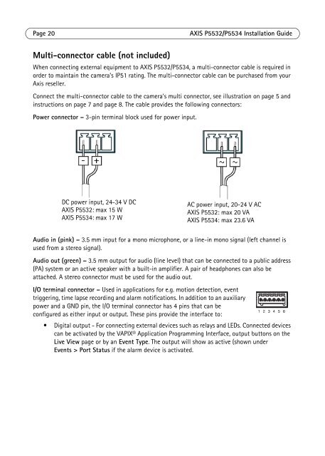
Multi-connector cable (not included)<br />
When connecting external equipment to <strong>AXIS</strong> <strong>P5532</strong>/<strong>P5534</strong>, a multi-connector cable is required in<br />
order to maintain the camera’s IP51 rating. The multi-connector cable can be purchased from your<br />
<strong>Axis</strong> reseller.<br />
Connect the multi-connector cable to the camera’s multi connector, see illustration on page 5 and<br />
instructions on page 7 and page 8. The cable provides the following connectors:<br />
Power connector – 3-pin terminal block used for power input.<br />
DC power input, 24-34 V DC<br />
<strong>AXIS</strong> <strong>P5532</strong>: max 15 W<br />
<strong>AXIS</strong> <strong>P5534</strong>: max 17 W<br />
AC power input, 20-24 V AC<br />
<strong>AXIS</strong> <strong>P5532</strong>: max 20 VA<br />
<strong>AXIS</strong> <strong>P5534</strong>: max 23.6 VA<br />
Audio in (pink) – 3.5 mm input for a mono microphone, or a line-in mono signal (left channel is<br />
used from a stereo signal).<br />
Audio out (green) – 3.5 mm output for audio (line level) that can be connected to a public address<br />
(PA) system or an active speaker with a built-in amplifier. A pair of headphones can also be<br />
attached. A stereo connector must be used for the audio out.<br />
I/O terminal connector – Used in applications for e.g. motion detection, event<br />
triggering, time lapse recording and alarm notifications. In addition to an auxiliary<br />
power and a GND pin, the I/O terminal connector has 4 pins that can be<br />
configured as either input or output. These pins provide the interface to:<br />
• Digital output - For connecting external devices such as relays and LEDs. Connected devices<br />
can be activated by the VAPIX® Application Programming Interface, output buttons on the<br />
Live View page or by an Event Type. The output will show as active (shown under<br />
Events > Port Status if the alarm device is activated.