Template BA B168xH238 - Hörmann
Template BA B168xH238 - Hörmann
Template BA B168xH238 - Hörmann
- No tags were found...

Create successful ePaper yourself
Turn your PDF publications into a flip-book with our unique Google optimized e-Paper software.
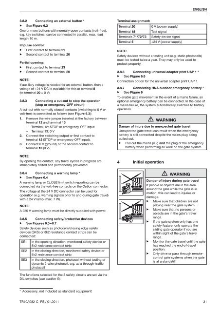
ENGLISH3.8.2▶ See Figure 6.2Connecting an external button *One or more buttons with normally open contacts (volt-free),e.g. key switches, can be connected in parallel, max. leadlength 10 m.Impulse control:▶ First contact to terminal 21▶ Second contact to terminal 20Partial opening:▶ First contact to terminal 23▶ Second contact to terminal 20Note:If auxiliary voltage is needed for an external button, then avoltage of +24 V DC is available for this at terminal 5(to terminal 20 = 0 V).3.8.3 Connecting a cut-out to stop the operator(stop or emergency-OFF circuit)A cut-out with normally closed contacts (switching to 0 V orvolt-free) is connected as follows (see Figure 6.3):1. Remove the wire jumper inserted at the factory betweenterminal 12 and terminal 13.– Terminal 12: STOP or emergency-OFF input– Terminal 13: 0 V2. Connect the switching output or first contact toterminal 12 (STOP or emergency-OFF input).3. Connect 0 V (ground) or the second contact toterminal 13 (0 V).Note:By opening the contact, any travel cycles in progress areimmediately halted and permanently prevented.3.8.4 Connecting a warning lamp *▶ See Figure 6.4A warning lamp or CLOSE limit switch reporting can beconnected via the volt-free contacts on the Option connector.The voltage at the 24 V DC connector can be used foroperation (e.g. warning signals prior to and during gate travel)with a 24 V lamp (max. 7 W).Note:A 230 V warning lamp must be directly supplied with power.3.8.5 Connecting safety/protective devices▶ See Figures 6.5 – 6.7Safety devices such as photocells/closing edge safetydevices (SKS) or 8k2 resistance contact strips can beconnected:SE1SE2SE3in the opening direction, monitored safety device or8k2 resistance contact stripin the closing direction, monitored safety device or8k2 resistance contact stripin the closing direction, photocell without testing ordynamic 2-wire photocell, e.g. as a through-trafficphotocellTerminal assignment:Terminal 20Terminal 18Terminals 71/72/73Terminal 50 V (power supply)Test signalSafety device signal+24 V (power supply)Note:Safety devices without a testing unit (e.g. static photocells)must be tested twice a year. They may only be used toprotect property!3.8.6 Connecting universal adapter print UAP 1 *▶ See Figure 6.8Connection option for the universal adapter print UAP 1.3.8.7 Connecting HNA outdoor emergency battery *▶ See Figure 6To enable gate movement in the event of a mains failure, anoptional emergency battery can be connected. In the case ofa mains failure, the system automatically switches to batteryoperation.WARNINGDanger of injury due to unexpected gate travelUnexpected gate travel can result when the emergencybattery is still connected despite the mains plug beingpulled out.▶ Pull out the mains plug and the plug of the emergencybattery when performing all work on the gate system.4 Initial operationWarningDanger of injury during gate travelIf people or objects are in the areaaround the gate while the gate is inmotion, this can lead to injuries ordamage.▶ Make sure that children are notplaying near the gate system.▶ Make sure that no persons orobjects are in the gate's travelrange.▶ If the gate system only has onesafety feature, only operate thesliding gate operator if you arewithin sight of the gate's travelrange.▶ Monitor the gate travel until the gatehas reached the end-of-travelposition.▶ Only drive or pass through remotecontrolgate systems when the gateis at a standstill!The functions selected for the 3 safety circuits are set via theDIL switches (see section 5).* Accessory, not included as standard equipment!TR10A082-C RE / 01.2011 31