Template BA B168xH238 - Hörmann
Template BA B168xH238 - Hörmann
Template BA B168xH238 - Hörmann
- No tags were found...
Create successful ePaper yourself
Turn your PDF publications into a flip-book with our unique Google optimized e-Paper software.
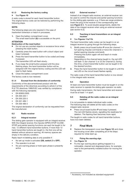
ENGLISH6.1.3▶ See Figure 10Restoring the factory codingA radio code is stored for each hand transmitter button.The original factory code can be restored by performing thefollowing steps.Note:The following steps are only required in the case ofinadvertent extension or teach-in processes.1. Open the battery compartment cover.The small reset button (5) is accessible on the print.ATTENTIONDestruction of the reset button▶ Do not use any pointed objects or excessive force whenpressing the reset button.2. Carefully press the reset button with a blunt object andkeep it pressed.3. Press the hand transmitter button to be coded and keepit pressed.The transmitter LED will flash slowly.4. If you keep the small button pressed until the slowflashing stops, the hand transmitter button will beassigned with the original factory coding and the LED willstart to flash faster.5. Close the battery compartment cover.The factory code is now restored.6.1.4 Excerpt from the declaration of conformityConformity of the abovementioned product with therequirements of the directives according to article 3 of theR & TTE directives 1999/5/EC was verified by compliancewith the following standards:• EN 60950:2000• EN 300 220-1• EN 300 220-3• EN 301 489-1• EN 300 489-3The original declaration of conformity can be requested fromthe manufacturer.6.2Radio receiver6.2.1 Integral receiverThe sliding gate operator is equipped with an integral receiver.With the integral receiver, the impulse (OPEN-STOP-CLOSE-STOP) and partial opening functions can each be taught in formax. 12 different hand transmitter buttons. If more than 12hand transmitter buttons are taught in, the first one will bedeleted without advance warning. All memory spaces areempty in the delivery condition.Radio teach-in/deleting data is only possible if:• No set-up mode is activated ( DIL switch 2 to OFF).• The operator is at rest.• No pre-warning phase or hold-open phase is presentlyactive6.2.2 External receiver *Instead of an integral radio receiver, an external receiver canbe used to control the impulse and partial opening functionsfor the sliding gate operator, e.g. if there are range problems.Insert the plug of the receiver in the corresponding slot(see Figure 6.1). To avoid double assignments, delete thedata of the integral receiver when using an external receiver(see section 6.5).6.3 Teaching in hand transmitters on an integralreceiver▶ See Figures 11a/11bThe hand transmitter radio codes can be taught in on anintegral receiver by going through the following steps.1. Briefly press circuit board button P once (for channel 1 =full opening impulse command) or twice (for channel 2 =partial opening impulse command).Pressing this button again will end teach-in modeimmediately.Depending on the channel being taught in, the red LEDwill flash 1x (for channel 1) or 2x (for channel 2). Duringthis time, a hand transmitter button can be taught in forthe desired function.2. Press the hand transmitter button to be taught in until thered LED on the circuit board flashes rapidly.The radio code of this hand transmitter button is now storedin the integral radio receiver.6.4 OperationAt least one hand transmitter button must be taught in on theradio receiver to operate the sliding gate operator via radio.During radio transmission, the hand transmitter and receivermust be at least 1 m apart.6.5 Deleting all the radio codes on an integralreceiverIt is not possible to delete individual radio codes.The following step will delete all the radio codes on theintegral radio receiver.▶ Press circuit board button P and keep it pressed.The red LED flashes slowly, signalling the readiness fordeletion. The flashing then becomes more rapid.The taught-in radio codes for all hand transmitter buttonshave now been deleted.7▶Final WorkReplace the transparent cover (see Figure 12) and closethe housing cover after completing all of the stepsrequired for initial start-up.7.1 Fixing the warning sign▶ See Figure 13▶ Fix the sign warning about getting trapped in anoticeable, cleaned and degreased place, for example,near to the permanently installed button for moving theoperator.* Accessory, not included as standard equipment!TR10A082-C RE / 01.2011 37


