Template BA B168xH238 - Hörmann
Template BA B168xH238 - Hörmann
Template BA B168xH238 - Hörmann
- No tags were found...

Create successful ePaper yourself
Turn your PDF publications into a flip-book with our unique Google optimized e-Paper software.
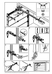
ENGLISHWARNINGDanger of crushing and shearingFingers or limbs may be crushed and severed if caught inthe toothed track or between the gate and closing edgewhile the gate is in motion.▶ Whenever the gate is moving, never touch the toothedtrack, toothed wheel, and the main or secondaryclosing edges.4.1 Preparation▶ Before initial start-up, check that all the connecting leadsare correctly installed at the connecting terminals.▶ Make sure that all DIL switches are set to the factorysetting (OFF) (see Figure 7), the gate is half open and theoperator engaged.Change the following DIL switches:▶ DIL switch 1: Installation direction (see Figure 7.1)– To ON, if the gate closes towards the right.– To OFF, if the gate closes towards the left.▶ DIL switches 3-7: Safety devices(see Figures 9.6/9.7/9.8)– Set according to the connected safety and protectivedevices (see section 5.3 – 5.5). These are, however,not active during set-up mode.4.2 Teaching in the gate's end-of-travel positions4.2.1 Recording the CLOSE end-of-travel position▶ See Figure 8.1aThe limit switch (reed contact) must be connected beforeteaching in the end-of-travel positions. The limit switch wiresmust be connected at the REED terminal.The option relay has the same function as the red LED duringset-up. The limit switch position can be viewed from afar witha connected lamp (see Figure 6.4).Teaching in the CLOSE end-of-travel position:1. Open the gate halfway.2. Set DIL switch 2 (set-up mode) to ON.The green LED slowly flashes, the red LED remains lit.3. Press circuit board button T and keep it pressed.The gate now travels in CLOSE direction at slow speed.The gate stops once the limit switch has been reached.4. Immediately release circuit board button T.The red LED goes out.The gate is now in the CLOSE end of travel position.Note:If the gate travels in the opening direction, DIL switch 1 is inthe wrong position and must be reset. Then repeat steps 1 to 4.If the position of the gate does not correspond to the desiredCLOSE position, a readjustment must be made.Readjusting the CLOSE end-of-travel position:1. Adjust the position of the magnet by moving the magnetslide.2. Press circuit board button T until the gate reaches thereadjusted end-of-travel position and the red LED goesout.3. Repeat steps 1 + 2 until the desired end-of-travelposition has been reached.4.2.2 Recording the OPEN end-of-travel position▶ See Figure 8.1bTeaching in the OPEN end-of-travel position:4. Press circuit board button T and keep it pressed.The gate now travels in OPEN direction at slow speed.5. Release circuit board button T, once the desired OPENend-of-travel position is reached.6. Press circuit board button P to confirm this position.The green LED flashes rapidly for 2 seconds to indicatethat the OPEN end-of-travel position has been recordedand then goes out.4.2.3 Recording the partial opening end-of-travelposition▶ See Figure 8.1cNote:If press-and-hold operation has been set, it is not possible torecord the partial opening end-of-travel position.Teaching in the partial opening end-of-travel position:1. Press circuit board button T and keep it pressed to movethe gate back towards the CLOSE position.The green LED will flash slowly.2. Release circuit board button T once the desired partialopening end-of-travel position is reached.3. Press circuit board button P to confirm this position.The green LED flashes rapidly for 2 seconds to indicatethat the partial opening end-of-travel position has beenrecorded and then goes out.4.2.4 Ending the set-up-mode▶ After you have finished the teach-in procedure, setDIL switch 2 back to OFF.The green LED signals that forces must be taught in byflashing quickly.The safety equipment is active again.4.2.5 Reference run▶ See Figure 8.2After teaching in the end-of-travel positions, the first cycle isalways a reference run. During this reference run the optionrelay clocks and a connected warning lamp flashes.Reference run to CLOSE end-of-travel position:▶ Press circuit board button T once.The operator automatically moves into the CLOSEend‐of-travel position.▶ If press-and-hold operation has been set ( DIL switch 16to ON), press and hold circuit board button T until thegate is in the close end-of-travel position.Note:Initial start-up is now finished if press-and-hold operation hasbeen set (DIL switch 16 to ON).4.3 Learning the forcesOnce the end-of-travel positions have been taught in and thereference run performed, force learning runs must also beperformed. For this, three successive gate cycles must takeplace, during which none of the safety devices may beactivated. Recording the forces takes place automatically bypress-and-release operation in both directions and the optionrelay clocks. The green LED flashes throughout. This LED issteadily illuminated once the force learning runs have beencompleted (see Figure 9.1).32 TR10A082-C RE / 01.2011