You also want an ePaper? Increase the reach of your titles
YUMPU automatically turns print PDFs into web optimized ePapers that Google loves.
Stage 4, the wheelhouse<br />
<strong>Le</strong> <strong>Courageux</strong><br />
Part Description Material Size in mm No. Notes<br />
No. off<br />
4.1 <strong>Le</strong>ft side panel ABS 1.5, machine-cut 1<br />
4.2 Right side panel ABS 1.5, machine-cut 1<br />
4.3 Back panel ABS 1.5, machine-cut 1<br />
4.4 Partition wall ABS 1.5, machine-cut 1<br />
4.5 Wheelhouse wall glazing PVC 0.5, oversize 2<br />
4.6 Wheelhouse wall ABS 1.5, machine-cut 1<br />
4.7 Floor ABS 1.5, machine-cut 1<br />
4.8 Wheelhouse back panel ABS 1.5, machine-cut 1<br />
4.9 Roof girder ABS 1.5, machine-cut 1<br />
4.10 Wheelhouse ceiling frame ABS 1.5, machine-cut 1<br />
4.11 Front wall doubler ABS 1.5, machine-cut 1<br />
4.12 Front wall ABS 1.5, machine-cut 1<br />
4.13 Hatch cover ABS 1.5, machine-cut 1<br />
4.14 Hatch cover ABS 1, machine-cut 1<br />
4.15 Hatch cover ABS 1, machine-cut 1<br />
4.16 Rear wheelhouse roof ABS 1, machine-cut 1<br />
4.17 Front wheelhouse wall ABS 1, machine-cut 1<br />
4.18 Right wheelhouse corner panel Resin Moulded 1<br />
4.19 <strong>Le</strong>ft wheelhouse corner panel Resin Moulded 1<br />
4.20 Wheelhouse side wall ABS 1, machine-cut 1<br />
4.21 Wheelhouse side wall ABS 1, machine-cut 1<br />
4.22 Glazing panels PVC 0.5, oversize 2 each<br />
4.23 Wheelhouse roof ABS 1, machine-cut 1<br />
Stage 4, the wheelhouse<br />
Use cyano for all joints in this stage, unless stated otherwise.<br />
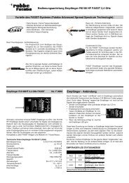
Figs. 115 - 117<br />
- Assemble the basic wheelhouse framework from parts 4.1<br />
- 4.4, taking care to keep the parts at right-angles. When<br />
fitting part 4.3 please note that the holes for the steps<br />
must be on the left-hand side.<br />
- Tape the parts together, and glue the joints.<br />
Fig. 118<br />
- Cut the glazing panels 4.5 to size and glue them to the<br />
inside of the wheelhouse wall 4.6.<br />
Figs. 119 - 120<br />
- Glue the wheelhouse wall and floor to the basic framework.<br />
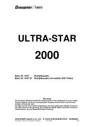
Figs. 121 and 122<br />
- Note the position of the holes when gluing the wheelhouse<br />
back panel 4.8 to the structure.<br />
- Glue the roof girder 4.9 and the wheelhouse ceiling frame<br />
4.10 in place.<br />
Figs. 123 and 124<br />
Assembly and operating instructions<br />
- Glue the doubler 4.11 to the front wall 4.12.<br />
- Glue the hatch cover 4.13 - 4.15 on top as shown.<br />
12<br />
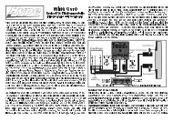
Fig. 125<br />
No.<br />
1025<br />
- Note the position of the holes when gluing the rear wheelhouse<br />
roof 4.16 in place. The hole for the stern light must<br />
be on the left-hand side - see arrow.<br />
Fig. 126<br />
- Cut the glazing panels 4.22 to size to match the shape of<br />
the wheelhouse walls 4.17 - 4.21.<br />
Fig. 127<br />
- Hold the glazing panels 4.22 in position as shown. Apply<br />
adhesive sparingly to the edges, to avoid soiling the visible<br />
glazed areas.