You also want an ePaper? Increase the reach of your titles
YUMPU automatically turns print PDFs into web optimized ePapers that Google loves.
Stage 9, the gallows<br />
<strong>Le</strong> <strong>Courageux</strong><br />
Part Description Material Size in mm No. Notes<br />
No. off<br />
Pulleys<br />
9.1 Pulley Aluminium 13 Ø x 6, machine-cut 4 FS<br />
9.2 Pulley block Resin Moulded 4 FS<br />
9.3 Pulley shaft Brass wire 2 Ø x 8 4<br />
9.4 Screw-hook Metal Ready made 4 FS<br />
9.5 Cross-bar Brass wire 2 Ø x 8 4<br />
9.6 Pulley Aluminium 13 Ø x 6, machine-cut 2 FS<br />
9.7 Pulley stand Resin Moulded 2 FS<br />
9.8 Pulley shaft Brass wire 2 Ø x 8 2<br />
9.9 Guard Resin Moulded 2 FS<br />
9.10 Pulley Aluminium 13 Ø x 6, machine-cut 2 FS<br />
9.11 Pulley bracket Resin Moulded 2 FS<br />
9.12 Pulley shaft Brass wire 2 Ø x 8 2<br />
9.13 Guard Resin Moulded 2 FS<br />
Gallows<br />
9.14 Fore gallows brace ABS section 6 x 6 x 120 4<br />
9.15 After gallows brace ABS section 6 x 6 x 120 4<br />
9.16 Fore gallows base plate Resin Moulded 2 FS<br />
9.17 After gallows base plate Resin Moulded 2 FS<br />
“S” Template ABS 1.5, machine-cut 1<br />
9.18 Fore gallows headpiece (V) Plastic Inj. moulded 2 FS<br />
9.19 After gallows headpiece (H) Plastic Inj. moulded 2 FS<br />
9.20 Split pin Brass 1 x 15 8 FS<br />
9.21 Hoop Brass wire 1.5 Ø, as drawing 4<br />
9.22 Nut Brass M 2 8 FS<br />
9.23 Front brace Brass tube 2.5 Ø x 140 2<br />
9.24 Rear brace Brass tube 2.5 Ø x 122 2<br />
9.25 Bracket Brass wire 1.5 Ø, as drawing 8<br />
9.26 Front trawl rope Thread 1 Ø x 2200 1 FS<br />
9.27 Rear trawl rope Thread 1 Ø x 2500 1 FS<br />
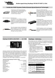
Figs. 209 and 210<br />
The four gallows pulleys<br />
- Place the sheaves (pulleys) 9.1 in the blocks 9.2, and fit<br />
the pulley shafts 9.3. Secure the shafts with a drop of<br />
cyano.<br />
- Fit the screw-hooks 9.4.<br />
- Glue the cross-bars 9.5 to the pulleys.<br />
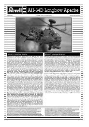
Fig. 211<br />
The vertical pulleys<br />
Assembly and operating instructions<br />
- Assemble the vertical pulleys from parts 9.5 - 9.9. Glue<br />
the guards 9.9 in place in a mirror-image pattern, i.e.<br />
make one right-hand and one left-hand pulley.<br />
22<br />
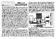
Fig. 212<br />
The side pulleys<br />
No.<br />
1025<br />
- The side pulleys are assembled from parts 9.10 - 9.13.