
Create successful ePaper yourself
Turn your PDF publications into a flip-book with our unique Google optimized e-Paper software.
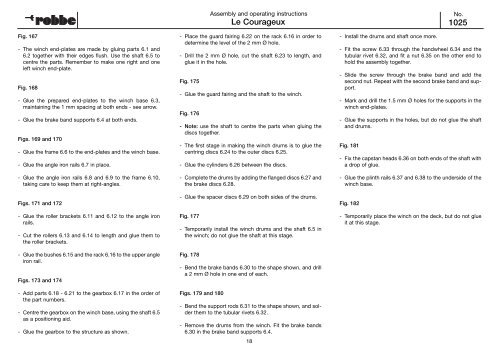
Fig. 167<br />
- The winch end-plates are made by gluing parts 6.1 and<br />
6.2 together with their edges flush. Use the shaft 6.5 to<br />
centre the parts. Remember to make one right and one<br />
left winch end-plate.<br />
Fig. 168<br />
- Glue the prepared end-plates to the winch base 6.3,<br />
maintaining the 1 mm spacing at both ends - see arrow.<br />
- Glue the brake band supports 6.4 at both ends.<br />
Figs. 169 and 170<br />
- Glue the frame 6.6 to the end-plates and the winch base.<br />
- Glue the angle iron rails 6.7 in place.<br />
- Glue the angle iron rails 6.8 and 6.9 to the frame 6.10,<br />
taking care to keep them at right-angles.<br />
Figs. 171 and 172<br />
- Glue the roller brackets 6.11 and 6.12 to the angle iron<br />
rails.<br />
- Cut the rollers 6.13 and 6.14 to length and glue them to<br />
the roller brackets.<br />
- Glue the bushes 6.15 and the rack 6.16 to the upper angle<br />
iron rail.<br />
Figs. 173 and 174<br />
- Add parts 6.18 - 6.21 to the gearbox 6.17 in the order of<br />
the part numbers.<br />
- Centre the gearbox on the winch base, using the shaft 6.5<br />
as a positioning aid.<br />
- Glue the gearbox to the structure as shown.<br />
<strong>Le</strong> <strong>Courageux</strong><br />
- Place the guard fairing 6.22 on the rack 6.16 in order to<br />
determine the level of the 2 mm Ø hole.<br />
- Drill the 2 mm Ø hole, cut the shaft 6.23 to length, and<br />
glue it in the hole.<br />
Fig. 175<br />
- Glue the guard fairing and the shaft to the winch.<br />
Fig. 176<br />
- Note: use the shaft to centre the parts when gluing the<br />
discs together.<br />
- The first stage in making the winch drums is to glue the<br />
centring discs 6.24 to the outer discs 6.25.<br />
- Glue the cylinders 6.26 between the discs.<br />
- Complete the drums by adding the flanged discs 6.27 and<br />
the brake discs 6.28.<br />
- Glue the spacer discs 6.29 on both sides of the drums.<br />
Fig. 177<br />
- Temporarily install the winch drums and the shaft 6.5 in<br />
the winch; do not glue the shaft at this stage.<br />
Fig. 178<br />
- Bend the brake bands 6.30 to the shape shown, and drill<br />
a 2 mm Ø hole in one end of each.<br />
Figs. 179 and 180<br />
Assembly and operating instructions<br />
- Bend the support rods 6.31 to the shape shown, and solder<br />
them to the tubular rivets 6.32.<br />
- Remove the drums from the winch. Fit the brake bands<br />
6.30 in the brake band supports 6.4.<br />
18<br />
- Install the drums and shaft once more.<br />
No.<br />
1025<br />
- Fit the screw 6.33 through the handwheel 6.34 and the<br />
tubular rivet 6.32, and fit a nut 6.35 on the other end to<br />
hold the assembly together.<br />
- Slide the screw through the brake band and add the<br />
second nut. Repeat with the second brake band and support.<br />
- Mark and drill the 1.5 mm Ø holes for the supports in the<br />
winch end-plates.<br />
- Glue the supports in the holes, but do not glue the shaft<br />
and drums.<br />
Fig. 181<br />
- Fix the capstan heads 6.36 on both ends of the shaft with<br />
a drop of glue.<br />
- Glue the plinth rails 6.37 and 6.38 to the underside of the<br />
winch base.<br />
Fig. 182<br />
- Temporarily place the winch on the deck, but do not glue<br />
it at this stage.