
Create successful ePaper yourself
Turn your PDF publications into a flip-book with our unique Google optimized e-Paper software.
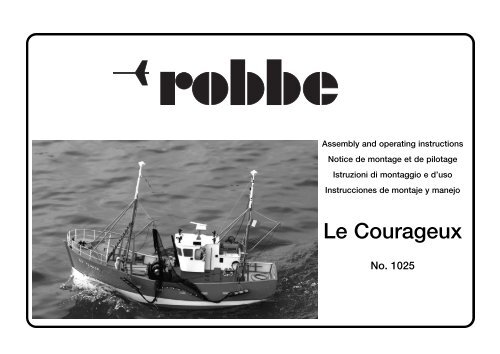
Assembly and operating instructions<br />
Notice de montage et de pilotage<br />
Istruzioni di montaggio e d’uso<br />
Instrucciones de montaje y manejo<br />
<strong>Le</strong> <strong>Courageux</strong><br />
No. 1025
Specification<br />
Overall length: approx. 820 mm<br />
Overall beam: approx. 300 mm<br />
Draught: approx. 140 mm<br />
Displacement: approx. 10,000 g<br />
Scale: 1 : 20<br />
Essential accessories not included in the kit are listed on<br />
the separate sheet, as are suitable adhesives.<br />
See the main robbe catalogue for details of tools and aids<br />
to building.<br />
Fittings Set, No. 1026, and Power Set, No. 1027<br />
These two sets are required in order to produce a boat of<br />
scale appearance which is capable of running on the water.<br />
Particular parts from the Fittings Set and the Power Set are<br />
required early on in the construction of the boat, and for this<br />
reason it makes good sense to obtain them before you start<br />
building the model.<br />
Sequence of assembly<br />
The <strong>Le</strong> <strong>Courageux</strong> is designed for the advanced model builder.<br />
We therefore assume that you have a certain minimum level<br />
of experience in modelling procedures, and in these instructions<br />
we do not go into details of preparatory work such as<br />
breaking out die-cut parts, drilling holes, cutting strip material<br />
and wire to length, painting individual parts, etc.<br />
Some stages are only sketched in, and are intended simply<br />
to indicate possible methods and to stimulate your own<br />
ideas.<br />
In basic terms the numbering of the components reflects<br />
the sequence of assembly.<br />
Please read through the instructions, referring to the parts<br />
lists, the illustrations and the plan, so that you have a clear<br />
idea of how each section goes together.<br />
The photographs show the parts and sub-assemblies in<br />
<strong>Le</strong> <strong>Courageux</strong><br />
their unpainted state, as this generally makes it easier to<br />
understand the arrangements. Some detail photos show the<br />
finished, painted components on the completed model.<br />
Vacuum-moulded parts<br />
Assembly and operating instructions<br />
Sand the cut edges of the vacuum-moulded parts smooth<br />
after cutting away the scrap material.<br />
Drill holes in the vacuum-moulded components at the marked<br />
points, using the sizes of drill stated in the illustrations.<br />
Machine-cut and die-cut parts<br />
Don’t separate these parts from their support sheets until<br />
you need them for the stage in hand.<br />
The identification drawings are intended to help you locate<br />
individual parts. Write the part number on each component.<br />
When gluing parts together, ensure that punched points are<br />
left exposed, and are still accessible for drilling.<br />
Don’t throw away the scrap material (sheet, strip and wire),<br />
as it may be needed later to make other small parts.<br />
All surfaces which are to be joined must be sanded beforehand<br />
to ensure that the glue adheres well.<br />
Use only the stated and recommended adhesives.<br />
Read and observe the instructions supplied with the various<br />
adhesives.<br />
Before gluing any parts together check “dry” (no glue) that<br />
they are an accurate fit.<br />
Note that Stabilit-Express should never be applied in the<br />
form of thick fillets; spread the adhesive out thinly.<br />
All glued joints involving holes in the hull, i.e. where water<br />
could penetrate (e.g. the rudder bush, propeller tube, etc.)<br />
should be sealed all-round with a thin fillet of Stabilit-<br />
Express.<br />
Parts should be held together using clamps or adhesive<br />
tape while glued joints are drying.<br />
2<br />
No.<br />
1025<br />
Small quantities of cyano-acrylate (Speed Extra, Speed<br />
Type 2) should be applied on the tip of a pin or a length of<br />
thin wire.<br />
When soldering railing components and similar parts<br />
together, use a hot iron and complete each joint quickly, as<br />
excess heat could easily damage the plastic (superstructure,<br />
platforms etc.). Alternatively you may wish to make up a<br />
simple jig for shaping and soldering the individual railing<br />
sections before they are installed on the model.<br />
Clean up all soldered joints carefully. All the metal parts<br />
should be prepared thoroughly prior to painting by rubbing<br />
them down with fine abrasive paper and removing all traces<br />
of grease.<br />
Fit a separate heat-shrink sleeve over each soldered joint<br />
between electrical cables.<br />
Directions such as “left” and “right” are as seen from the<br />
stern of the model, looking forward.<br />
All dimensions in the text and the illustrations are stated<br />
in mm.<br />
Notes on painting<br />
Wooden parts should be given two or three coats of wood<br />
wax to render them waterproof.<br />
Any gaps between plastic parts can be made good using a<br />
plastic filler paste such as robbe rostuff-micro. Sand the filler<br />
back flush when it has set hard.<br />
Parts to be painted must be cleaned thoroughly beforehand<br />
by wiping them with methylated spirit or similar (not cellulose<br />
thinners). Try not to touch the surfaces at all between<br />
cleaning and painting. Before applying the colour finish to<br />
the hull we recommend that you give it a coat of primer and<br />
rub it down to obtain a smooth surface.<br />
If you wish to obtain a clean, neatly delineated colour scheme,<br />
you must paint the model’s components in a particular<br />
sequence:<br />
Each part which is to be a different colour should first be<br />
trimmed to fit accurately on the boat, then painted, and
finally screwed or glued to the model once the paint is dry.<br />
If any part is to be painted in multiple colours, mask the<br />
areas out using Tesafilm (clear cellulose tape) or PVC tape –<br />
don’t use paper masking tape. The tape should be peeled<br />
off carefully as soon as the paint is touch-dry.<br />
Where painted parts have to be glued to the model, sand the<br />
painted surface beforehand to provide a mechanical “key”<br />
for the adhesive.<br />
At some junctures it makes sense to paint assemblies before<br />
continuing with construction; the instructions tell you<br />
when this is necessary. Otherwise it is left up to you when to<br />
paint the boat.<br />
For this model we recommend the use of acrylic or synthetic<br />
enamel paints only. You can use brushing types or spray<br />
cans according to your preference.<br />
If you have access to paint spraying equipment, we recommend<br />
the use of two-pack car paints. Use only one type or<br />
make of paint to avoid compatibility problems.<br />
We suggest that you emulate the colour scheme shown in<br />
the kit box illustration.<br />
Painting the hull and waterline<br />
Since the Construction Water Line (CWL) is also the dividing<br />
line between the exposed hull paintwork and the submerged<br />
paintwork, the line should be marked on the hull before<br />
painting commences.<br />
Mark the waterline at the centre of the bow and stern, as<br />
shown on the plan. Measure the height of the hull on both<br />
sides; the values must be identical.<br />
The easiest method of marking the waterline is to make up<br />
a simple jig as shown in the drawing alongside.<br />
Place the hull in the stand and weight it down, so that it cannot<br />
shift. Now pack up the boatstand at one end so that the<br />
height of the CWL mark is the same at the bow and stern;<br />
this is best checked using a steel ruler.<br />
Set the prepared marking jig to the correct height, then run<br />
Assembly and operating instructions<br />
<strong>Le</strong> <strong>Courageux</strong><br />
it all round the hull to mark the waterline on the surface. The<br />
hull will later be painted up to this line.<br />
The rubbing strakes 12.31 form the second dividing line between<br />
the hull colours. Measure off the position of the rubbing<br />
strakes from the plan, and mark the lines on the hull.<br />
Jig for marking the waterline (CWL)<br />
--<br />
CWL = CWL<br />
Höhenverstellung = Height adjustment<br />
Bleistift = Pencil<br />
Klemme = Clamp<br />
Schraube = Screw<br />
Holzklotz = Wood block<br />
Bauunterlage = Bench surface<br />
--<br />
Radio control equipment<br />
We recommend that you install the listed RC components,<br />
which are shown in the photos. If you wish to use other<br />
components, you can still follow the basic arrangement<br />
shown, but you may have to make allowance for differences<br />
in component size.<br />
Connect the radio control system, set the transmitter sticks<br />
and trims to centre, and switch the system on: this will<br />
cause all the servos to run to their true centre.<br />
Electrical connections inside the hull must be positioned<br />
and protected in such a way that they cannot come into<br />
contact with water.<br />
Auxiliary working systems<br />
The boat is large enough to accommodate a wide range of<br />
the extra working systems which are present on the full-size<br />
vessel. For example, the boat can be fitted with a lighting<br />
system, rotating radar, siren, simulated diesel engine noise<br />
and horn.<br />
The instructions describe the installation of the various auxi-<br />
3<br />
No.<br />
1025<br />
liary systems at the appropriate point. We strongly recommend<br />
that you fit the components required when suggested,<br />
as it will inevitably be more difficult to install them at a later<br />
stage.<br />
The Parts Lists<br />
N.I. Not included<br />
PS Included in the Power Set<br />
FS Included in the Fittings Set<br />
Contents<br />
Stage Page<br />
0, Boatstand 4<br />
1, Hull 4<br />
2, Power system 6<br />
3, Deck 8<br />
4, Wheelhouse 12<br />
5, Wheelhouse fittings 13<br />
6, Winch 17<br />
7, Deck fittings 19<br />
8, Masts 20<br />
9, Gallows 22<br />
10, Otter boards and net 24<br />
11, Rudder system and RC installation 25<br />
12, Rigging, final work 28<br />
Appendix, with illustrations and drawings
Stage 0, the boatstand<br />
<strong>Le</strong> <strong>Courageux</strong><br />
Part Description Material Size in mm No. Notes<br />
No. off<br />
0.1 Boatstand ABS 2, vac. moulded 1<br />
0.2 Base plate Plywood 5 x 275 x 464 1 N.I.<br />
Stage 1, the hull<br />
Part Description Material Size in mm No. Notes<br />
No. off<br />
1.1 Hull ABS 3, vac.-moulded 1<br />
1.2 Rear keel section ABS 1.5, machine-cut 1<br />
1.3 Rear keel section ABS 3, machine-cut 2<br />
1.4 Centre keel section ABS 1.5, machine-cut 1<br />
1.5 Centre keel section ABS 3, machine-cut 2<br />
1.6 Front keel section ABS 1.5, machine-cut 1<br />
1.7 Front keel section ABS 3, machine-cut 2<br />
1.8 Half-bulkhead ABS 3, machine-cut 1<br />
1.9 Stern deck support ABS 3, machine-cut 1<br />
1.10 Transom ABS 3, machine-cut 1<br />
1.11 Stern bulkhead ABS 3, machine-cut 1<br />
1.12 Support bulkhead ABS 3, machine-cut 1<br />
1.13 Motor bulkhead ABS 3, machine-cut 1<br />
1.14 Battery bulkhead ABS 3, machine-cut 1<br />
1.15 Stern tube bulkhead ABS 3, machine-cut 1<br />
1,16 Support strip ABS 3 x 10 x 170 2<br />
1.17 Retaining strip ABS 3 x 10 x 170 2<br />
1.18 RC bulkhead ABS 3, machine-cut 1<br />
1.19 Loudspeaker bulkhead ABS 3, machine-cut 1<br />
1.20 RC plate ABS 1.5, machine-cut 1<br />
1.21 Half-bulkhead ABS 3, machine-cut 1<br />
1.22 Deck support ABS 3, machine-cut 1<br />
1.23 Forecastle deck bulkhead ABS 3, machine-cut 1<br />
1.24 Bow bulkhead ABS 3, machine-cut 1<br />
1.25 Doubler, rudder spigot ABS 1.5, machine-cut 2<br />
Assembly and operating instructions No.<br />
4<br />
1025
Stage 1, the hull<br />
Fig. 1<br />
- The boatstand 0.1 is supplied as a ready-made vacuummoulded<br />
item. We recommend that you glue a plywood<br />
floor plate 0.2 inside it to stiffen the moulding; dimensions:<br />
5 x 275 x 464 mm.<br />
Fig. 2<br />
- The domed section at the stern of the hull 1.1 should be<br />
removed completely; sand the cut edges smooth.<br />
Fig. 3<br />
- The component parts of the keel.<br />
- Note: the three-part keel is assembled from two outer layers<br />
(3 mm thick) and one centre layer (1.5 mm thick). The<br />
prepared keel components are subsequently glued<br />
together inside the hull.<br />
Fig. 4<br />
- The example in the picture shows the rear keel components<br />
1.2 and 1.3.<br />
- We recommend that you make a jig for gluing the keel<br />
parts together; this consists of a wooden board and<br />
several nails, as shown in the photo. The jig ensures that<br />
the laminated components are joined with their edges<br />
flush.<br />
Fig. 5<br />
- Laminate the keel components using cyano.<br />
Fig. 6<br />
- The prepared, laminated keel components.<br />
Fig. 7<br />
Assembly and operating instructions<br />
<strong>Le</strong> <strong>Courageux</strong><br />
- Place the keel components 1.2 - 1.7 in the hull, and trim<br />
them to fit if necessary. Don’t glue them in place at this<br />
stage.<br />
Fig. 8<br />
- Mark a line on both sides of the rear keel component 1.2,<br />
1.3 where it meets the outside edge of the hull. The projecting<br />
part forms the rudder spigot; do not apply glue to<br />
this area.<br />
Fig. 9<br />
Use Stabilit-Express for this stage.<br />
- Apply adhesive to the joint surfaces of the rear keel component<br />
1.2, 1.3, place the part in the hull and clamp it in<br />
place as shown.<br />
Fig. 10<br />
- Glue the central keel component 1.4, 1.5 in place as<br />
shown.<br />
Fig. 11<br />
- Glue the front keel component 1.6, 1.7 in the hull.<br />
Fig. 12<br />
- The component parts 1.8 - 1.10 of the transom.<br />
Figs. 13 and 14<br />
- Laminate parts 1.8 - 1.10 to form the transom as shown,<br />
using cyano. Take care to keep the edges flush.<br />
5<br />
Fig. 15<br />
No.<br />
1025<br />
- Trim the edges of the prepared transom to fit snugly in the<br />
hull; it must be at right-angles to the hull centreline. Tape<br />
it in place.<br />
Fig. 16<br />
- Apply Stabilit-Express to the joint between the transom<br />
1.8 - 1.10 and the hull, taking care to produce a watertight<br />
joint all round.<br />
Fig. 17<br />
- The stern bulkhead 1.11 and the support bulkhead 1.12.<br />
Fig. 18<br />
- Trim the bulkheads 1.11 and 1.12 to fit, position them<br />
carefully and fix them in the hull using cyano.<br />
Fig. 19<br />
- The motor bulkhead 1.13, the battery bulkhead 1.14 and<br />
the stern tube bulkhead 1.15, with the support strips 1.16<br />
and the retaining strips 1.17.<br />
Fig. 20<br />
- Place the bulkheads 1.13, 1.14 in the hull together with<br />
the support strips 1.16; do not glue them at this stage.<br />
Fig. 21<br />
- Place the stern tube bulkhead 1.15 in the hull.<br />
Fig. 22<br />
- Place the retaining strips 1.17 in position.
Fig. 23<br />
- The RC bulkhead 1.18, the loudspeaker bulkhead 1.19<br />
and the RC plate 1.20.<br />
Fig. 24<br />
- Place the RC bulkhead 1.18 and the speaker bulkhead<br />
1.19 in the hull as shown.<br />
Fig. 25<br />
- Place the RC plate 1.20 in position, as shown in the<br />
photo.<br />
Fig. 26<br />
- Adjust the position of all the bulkheads so that they fit<br />
snugly against each other. Check that they are all at rightangles<br />
to the hull centreline.<br />
- Tack the bulkheads to the hull using cyano; don’t glue the<br />
RC plate at this stage.<br />
Fig. 27<br />
- The component parts of the forecastle deck bulkhead.<br />
Stage 2, the power system<br />
Fig. 28<br />
<strong>Le</strong> <strong>Courageux</strong><br />
- Glue the half-bulkhead 1.21, the deck support 1.22 and<br />
the forecastle deck bulkhead 1.23 together, taking care to<br />
keep the edges flush.<br />
Figs. 29 and 30<br />
- Place the forecastle deck bulkhead 1.21 - 1.23 and the<br />
bow bulkhead 1.24 in the hull, position them carefully and<br />
fix them in place with cyano.<br />
Figs. 31 and 32<br />
- Remove the RC plate 1.20. Apply a thin fillet of Stabilit-<br />
Express to all the joints between the bulkheads and the<br />
hull.<br />
- The RC bulkhead 1.18 can now be glued in place permanently.<br />
Fig. 33<br />
- The RC plate 1.20 can now be glued in place permanently.<br />
Fig. 34<br />
Assembly and operating instructions<br />
- The rear keel section doublers 1.25 (rudder spigot).<br />
6<br />
Figs. 35 and 36<br />
No.<br />
1025<br />
- Glue the doublers to the rear projecting part of the keel<br />
one by one, clamping them in place as shown.<br />
- Allow the glue to set hard, then clean up any excess<br />
adhesive.<br />
Figs. 37 and 38<br />
Part Description Material Size in mm No. Notes<br />
No. off<br />
2.1 Electric motor --- Ready made 1 P.S.<br />
2.2 Suppressor set --- 1 x 47 nF, 2 x 100 nF 1 P.S.<br />
2.3 Motor leads --- 1 x red, 1 x black 2 P.S.<br />
2.4 AMP plug --- Ready made 2 P.S.<br />
2.5 Insulator Plastic Ready made 1 P.S.<br />
2.6 Socket-head screw Steel M4 x 10 2 P.S.<br />
2.7 Washer Steel 4.3 I.D. 2 P.S.<br />
- Drill the hole for the stern tube, working from the rear,<br />
starting with a 3 mm Ø bit. Use progressively larger drills<br />
until the hole is 7 mm Ø. Clamp the 7 mm Ø bit in the<br />
chuck in such a way that the hole can be continued<br />
through the support bulkhead 1.12.<br />
Fig. 39<br />
- Drill a 4 mm Ø hole in the rear keel section to accept the<br />
top rudder bush.<br />
Fig. 40<br />
- Drill a 4 mm Ø hole in the projecting keel section to accept<br />
the bottom rudder bush.
<strong>Le</strong> <strong>Courageux</strong><br />
Part Description Material Size in mm No. Notes<br />
No. off<br />
2.8 Locknut Brass M4 1 P.S.<br />
2.9 Propeller shaft Steel 4 Ø x 300 1 P.S.<br />
2.10 Stern tube Brass 6.5 Ø x 267 1 P.S.<br />
2.11 Collet and M3 x 3 grubscrew Brass 4 Ø x 7 Ø x 5 1 P.S.<br />
2.12 Hexagon driver Brass 5 I.D. 1 P.S.<br />
2.13 Hexagon driver Brass 4 I.D. 1 P.S.<br />
2.14 Shaft coupling Plastic Ready made 1 P.S.<br />
2.15 Grubscrew Steel M3 x 5 2 P.S.<br />
2.16 Rudder bush Brass 3 Ø x 4 Ø x 35 1 Tubular rivet<br />
2.17 Rudder bush Brass 3 Ø x 4 Ø x 30 1 Tubular rivet<br />
“HD” Jig rod Brass 3 Ø x 180 1<br />
Stage 2, the power system<br />
Figs. 41 and 42<br />
- The component parts of the power system.<br />
Fig. 43<br />
- Suppress the motor 2.1 using the suppressor set 2.2.<br />
When soldering the motor wires 2.3 to the motor, note that<br />
the red wire must be soldered to the motor terminal with<br />
the red dot.<br />
- Attach the AMP plug 2.4 to the motor wires, and push the<br />
insulator 2.5 over the contacts, with the red wire located<br />
under the projecting lug.<br />
Fig. 44<br />
- Place the motor in the hull and fix it to the bulkhead using<br />
the socket-head screws 2.6 and washers 2.7.<br />
Fig. 45<br />
- Fit the locknut 2.8 on the threaded end of the propeller<br />
shaft 2.9.<br />
- Sand the outside of the stern tube 2.10 lightly, fill the tube<br />
Assembly and operating instructions<br />
with grease and insert it in the hull from the stern.<br />
- Push the propeller shaft into the tube, and fit the collet<br />
2.11 and grubscrew on the front end.<br />
- Insert the drivers 2.12 and 2.13 in the shaft coupling 2.14,<br />
and fit the grubscrews 2.15 in the coupling. Install the<br />
coupling, and check that it is possible to engage the propeller<br />
shaft without using force; the stern tube must not be<br />
a tight fit in the holes. Adjust the holes in the hull if necessary.<br />
Fig. 46<br />
- Set a spacing of around 3 mm at the stern as shown in the<br />
photo, and only then tighten the grubscrews 2.15 in the<br />
shaft coupling.<br />
Fig. 47<br />
- Check once more by hand that the propeller shaft rotates<br />
freely and smoothly, then glue the stern tube 2.10 in place<br />
using Stabilit-Express. Ensure that the glued joint is<br />
watertight where the tube passes through the hull.<br />
- Press the collet 2.11 against the stern tube bearing, and<br />
tighten the grubscrew.<br />
7<br />
Fig. 48<br />
No.<br />
1025<br />
- Cut down the rudder bush 2.17 to a length of 25 mm.<br />
Figs. 49 and 50<br />
- Place the rudder bushes 2.16 and 2.17 in the appropriate<br />
holes, and fit the jig rod “HD” through both. Check that the<br />
rod is a smooth, sliding fit; it should rotate freely when turned<br />
by hand.<br />
- The jig rod must run parallel to the keel when viewed from<br />
the stern.<br />
- Adjust the holes for the rudder bushes if necessary, then<br />
glue them to the hull.<br />
- Cut off the bottom end of part 2.17 where it projects<br />
beyond the keel spigot.
Stage 3, the deck<br />
<strong>Le</strong> <strong>Courageux</strong><br />
Part Description Material Size in mm No. Notes<br />
No. off<br />
3.1 Switch plate ABS 3, machine-cut 1<br />
3.2 Rear hatch frame ABS 1.5, machine-cut 1<br />
3.3 Fore-and-aft girder ABS 3 x 10 x 700 2<br />
3.4 Deck girder ABS 3, machine-cut 3<br />
3.5 Rear deck ABS 1.5, machine-cut 1<br />
3.6 <strong>Le</strong>ft / right deck sections ABS 1.5, machine-cut 2<br />
3.7 Rear deck ABS 1.5, machine-cut 1<br />
3.8 Hatch ABS 1.5, machine-cut 1<br />
3.9 Rudder hatch ABS 1.5, machine-cut 1<br />
3.10 Hatch girder ABS 3, machine-cut 4<br />
3.11 Hatch girder ABS 3, machine-cut 2<br />
3.12 Forecastle deck ABS 1.5, machine-cut 1<br />
3.13 Forestem doubler ABS 3, machine-cut 2<br />
3.14 Forestem doubler ABS 3, machine-cut 2<br />
3.15 Tube ABS 35 Ø x 40 2<br />
3.16 Deck planking strake Spruce 1.5 x 8 x 200 ---<br />
3.17 Peripheral deck strip ABS 2 x 5, oversize 14<br />
3.18 Hull side bulwark stanchion ABS 5 x 5, oversize 32<br />
3.19 Rear bulwark stanchion ABS 2 x 5, oversize 4<br />
3.20 Inner handrail fairing ABS 2 x 5, oversize 2<br />
3.21 Forecastle deck bulwark ABS 2 x 5, oversize 1<br />
3.22 Hull side handrail ABS 2 x 10, oversize 2<br />
3.23 Transom handrail ABS 2 x 10, oversize 1<br />
3.24 Breakwater ABS 1, machine-cut 1, Two-part<br />
3.25 Step Brass 1.5 Ø, as drawing 4<br />
3.26 Porthole Brass 8 Ø 2 FS<br />
3.27 Glazing disc Plastic Ready made 2 FS<br />
3.28 <strong>Le</strong>ft door ABS Inj. moulded 1 FS<br />
3.29 Right door ABS Inj. moulded 1 FS<br />
3.30 Handle Brass 1 Ø, as drawing 10<br />
3.31 Scupper hatch ABS 1, machine-cut 10<br />
3.32 Front belaying pin rail ABS 3 x 3 x 85 2<br />
3.33 Rear belaying pin rail ABS 3 x 3 x 110 2<br />
Stage 3, the deck<br />
Fig. 51<br />
- The switch plate 3.1 and the rear hatch frame 3.2.<br />
Fig. 52<br />
Assembly and operating instructions<br />
- Glue parts 3.1 and 3.2 in the hull as shown in the photograph.<br />
8<br />
Fig. 53<br />
No.<br />
1025<br />
- Bevel the front edge of the fore-and-aft girders 3.3.
Fig. 54<br />
- Place the girders 3.3 in the hull, and trim them to fit neatly<br />
if necessary.<br />
Fig. 55<br />
- Trim the girders to fit accurately against the transom, then<br />
glue them in the notches in the bulkheads.<br />
Fig. 56<br />
- Glue together two of the three deck girders 3.4 with their<br />
edges flush.<br />
Fig. 57<br />
- Place the rear deck 3.5 in the hull, butting up against the<br />
transom. Position it centrally on the fore-and-aft girders,<br />
and mark the location of its front edge on both girders -<br />
points “M1”.<br />
Fig. 58<br />
- Glue the laminated deck girder 3.4 in place, with the marked<br />
points “M1” in the centre of the girder.<br />
Fig. 59<br />
- Glue the third deck girder 3.4 to the front face of the loudspeaker<br />
bulkhead 1.19.<br />
Figs. 60 - 62<br />
- Notches now have to be cut in the fore-and-aft girders to<br />
accept the large hatch when it is subsequently fitted: the<br />
slots should be 3 mm wide and 5 mm deep.<br />
Hold two hatch girders 3.11 together and use them as a<br />
spacer when cutting the notches, to ensure that they<br />
are the correct distance from the bulkheads.<br />
<strong>Le</strong> <strong>Courageux</strong><br />
- Start with the motor bulkhead 1.13, filing out the notches<br />
as shown in Figs. 60 and 61. Cut the notches in the stern<br />
tube bulkhead next, followed by the notches in the stern<br />
tube bulkhead 1.15, again using two hatch girders 3.11 as<br />
a spacer.<br />
- Mark the position of the remaining two notches in the<br />
fore-and-aft girders on each side: they should be located<br />
centrally between the bulkheads.<br />
Fig. 63<br />
- The individual deck components 3.5 - 3.8.<br />
Fig. 64<br />
- Fit together the deck components 3.5, 3.6 and 3.8, check<br />
that there are no gaps, and fix them together using paper<br />
masking tape.<br />
- Tape the front deck section 3.7 to the other panels, set<br />
back by about 10 mm as shown.<br />
- Mask off the underside of the side deck sections 3.6<br />
using paper masking tape.<br />
- The rudder hatch 3.9 is not required until later (Fig. 89).<br />
Figs. 65 and 66<br />
- Place the complete deck assembly in the hull, and trim<br />
the side deck sections to fit neatly at the bow.<br />
Figs. 67 and 68<br />
- Tack just the rear deck section 3.5 to the bulkheads, the<br />
girders and the hatch frame using cyano; the side deck<br />
sections must not be glued in place at this stage.<br />
Fig. 69<br />
Assembly and operating instructions<br />
- Release the forward deck and trim it so that it rests only<br />
9<br />
No.<br />
1025<br />
on the girder 3.4, i.e. not on the loudspeaker bulkhead<br />
1.19. Tack the deck section in place using cyano.<br />
Fig. 70<br />
- Remove the masking tape on the underside of the side<br />
deck components.<br />
- Press the side deck sections onto the bulkheads using<br />
scrap wood and spring clamps.<br />
Fig. 71<br />
- Tack the deck components in place using cyano.<br />
Figs. 72 and 73<br />
- Allow the glue to set hard, then apply a thin fillet of<br />
Stabilit-Express all round the joint between the deck and<br />
the hull. This is done by masking off the entire deck and<br />
the inside of the hull (coamings, transom and forecastle<br />
deck bulkhead) with paper masking tape, leaving a gap<br />
about 1 - 2 mm wide all round.<br />
- Apply adhesive to the joint between the hull and deck<br />
along this gap. Remove the strips of masking tape before<br />
the adhesive has hardened.<br />
Fig. 74<br />
- Mark the overhang at the edge of the hatch, and trim the<br />
hatch 3.8 to fit between the deck components with no<br />
gaps.<br />
Fig. 75, the hatch retainer system in principle<br />
- Fig. 75 shows the prepared hatch and the hatch girders<br />
3.10. The hatch is held in place using the bayonet mount<br />
principle, and that is why the hatch girders are offset relative<br />
to the hull bulkheads. The girders engage in the notches<br />
in the fore-and-aft girders, and the hatch is locked in<br />
place simply by sliding it forward.
Fig. 76<br />
- Place the hatch on the deck and slide it into the opening<br />
until it fits flush.<br />
- Now mark the front edge of each notch on the edge of<br />
the hatch - points “M2”.<br />
Fig. 77<br />
- Draw a centreline on the underside of the hatch. Mark the<br />
points “M2” on the underside of the hatch, and draw a<br />
line between each pair of points.<br />
- The position of the hatch girders 3.11 can now be marked.<br />
- Mark a centreline on all the hatch girders 3.10 and 3.11.<br />
Fig. 78<br />
- Place the girders on the hatch, with the rear edge coinciding<br />
with the lines drawn between the points “M2”. Tack<br />
each girder in place with a drop of cyano applied in the<br />
centre only.<br />
Figs. 79 and 80<br />
- Press the girders against the hatch using spring clamps,<br />
then glue them to the hatch by running cyano along the<br />
joints.<br />
Fig. 81<br />
- Place the hatch in the opening in the deck, and allow it to<br />
snap into place.<br />
Fig. 82<br />
- Chamfer the front edge of the forecastle deck 3.12 as<br />
shown in the photo.<br />
Fig. 83<br />
<strong>Le</strong> <strong>Courageux</strong><br />
- Place the forecastle deck 3.12 on the hull, trim it to fit and<br />
glue it in place as shown.<br />
Fig. 84<br />
- The forestem doublers 3.13 and 3.14.<br />
Fig. 85<br />
- Glue the doublers 3.13 and 3.14 on either side of the forestem.<br />
Fig. 86<br />
- Glue the lengths of tubing 3.15 in the right and left holes<br />
in the loudspeaker bulkhead 1.19.<br />
The deck planking<br />
Fig. 87<br />
- Place the main hatch on the model.<br />
- Mark a fore-and-aft centreline on the deck, then draw<br />
transverse lines across the hull at intervals of 100 mm,<br />
starting at the stern.<br />
Figs. 88 and 89<br />
Assembly and operating instructions<br />
- Locate the planking strakes 3.16 required for the deck,<br />
and cut them to a basic length of 200 mm.<br />
- Start with the central planking strake (3.16), which should<br />
be glued to the deck full-length. Where the planking is<br />
interrupted by hatches, cut the strake off and continue<br />
with the same piece, so that the grain of the wood is<br />
maintained. Take care to glue the initial strakes 3.16 exactly<br />
along the centreline.<br />
10<br />
Fig. 90<br />
No.<br />
1025<br />
- Continue the procedure by adding strakes to right and left<br />
of the central plank, again starting at the bow, but this<br />
time with a half-length strip.<br />
- The third strake should again begin with a full-length strip.<br />
This method produces a strake offset of 100 mm, and<br />
gives the characteristic planking pattern. We recommend<br />
that you apply the planking strakes to the deck alternately<br />
to right and left of centre.<br />
- The next page shows a complete plan view of the deck<br />
planking.<br />
Page 29: Overview of deck planking<br />
Fig. 91<br />
- Take care not to glue the hatches in place when applying<br />
the deck planking.<br />
Fig. 92<br />
- Continue with this procedure until you have planked the<br />
entire deck. Trim the edges of the strakes very carefully<br />
where they fit against the hull sides before gluing them in<br />
place.<br />
- Allow the glue to set hard, then sand the whole deck<br />
using fine abrasive paper.<br />
Figs. 93 and 94<br />
- Carefully file the scuppers down flush with the deck, and<br />
sand the edges smooth.<br />
Figs. 95 and 96<br />
- Apply the peripheral deck strips 3.17, starting with the<br />
transverse strip at the forecastle deck bulkhead.<br />
- Trim the strips to fit as far as the scuppers, alternating<br />
from side to side, and glue them in place. If you intend to
paint the strips before installing them, mark them individually<br />
so that you can identify them easily.<br />
Figs. 97 and 98<br />
- Mark the position of the hull side bulwark stanchions<br />
3.18. The first stanchion should be fitted between the hull<br />
side bulwark and the forecastle deck bulwark. Position<br />
the next two stanchions between the bulkhead and the<br />
first scupper, spaced out equally. Install additional<br />
stanchions adjacent to the scuppers.<br />
- Fit two stanchions between the rear scupper and the transom,<br />
again spaced out equally.<br />
- Measure the position of the four stern bulwark stanchions<br />
3.19 and mark these points.<br />
Figs. 99 and 100<br />
- Mark the length of the hull side bulwark stanchions 3.19<br />
individually, leaving them about 1 mm oversize. Cut them<br />
to length and glue them in place on both sides of the hull.<br />
Fig. 101<br />
- Glue the stern bulwark stanchions 3.19 in place - see also<br />
Figs. 104 and 106.<br />
- File back the excess hull material at the transom, and<br />
sand the edges smooth.<br />
Fig. 102<br />
- Trim the inner handrail fairings 3.20 to length and glue<br />
them to the bulwarks as shown.<br />
Fig. 103<br />
- Sand the projecting bulwark stanchions back flush with<br />
the hull and the inner handrails.<br />
Fig. 104<br />
<strong>Le</strong> <strong>Courageux</strong><br />
- Locate the one-piece bulwark 3.21 for the forecastle<br />
deck, trim it to fit, and glue it in place starting from the<br />
centre. Use cyano for this, applied drop by drop on the tip<br />
of a length of wire.<br />
- Run drops of cyano along the bulwark so that it is glued<br />
along its full length.<br />
Fig. 105<br />
- The next step is to stick the hull side handrails to the<br />
model, but first it is sensible to mask out the inside and<br />
outside of the hull sides.<br />
- Trim the side handrails 3.22 to fit.<br />
- Start by applying Stabilit-Express to the top of the bulwark<br />
stanchions; place the handrails in position, and tape<br />
them in place.<br />
- Allow drops of cyano to run along the joints so that the<br />
handrails are glued to the hull over their full length.<br />
Fig. 106<br />
- Trim the transom handrail 3.23 to fit, and glue it in place.<br />
Sand back the excess length of the hull side handrails<br />
3.22 when the glue has set hard.<br />
Fig. 107<br />
- Sand back the hull side handrails 3.22 flush with the hull.<br />
Fig. 108<br />
- Tape together the two parts of the breakwater 3.24.<br />
Fig. 109<br />
Assembly and operating instructions<br />
- Draw a fore-and-aft centreline on the forecastle deck.<br />
11<br />
No.<br />
1025<br />
- Place the breakwater on the model, and check that there<br />
are no gaps between it and the forecastle deck.<br />
- Tape the breakwater in position, and fix it in place using<br />
cyano.<br />
Fig. 110<br />
- Bend the steps 3.25 to the shape shown in the full-size<br />
drawing, using 1.5 mm Ø brass rod.<br />
- Fit the glazing discs 3.27 in the portholes 3.26, and press<br />
them into the doors 3.28 and 3.29.<br />
Fig. 111<br />
- Glue the prepared steps 3.25 and the doors 3.28 and 3.29<br />
to the forecastle deck bulwark as shown in the photo.<br />
Fig. 112<br />
- Bend the handles 3.30 for the scupper hatches 3.31 to<br />
the shape shown in the full-size drawing, and glue them<br />
in the hatch covers.<br />
- File back the projecting ends of the handles flush with the<br />
inside of the hatch covers.<br />
Figs. 113 and 114<br />
- Glue the scupper hatches 3.31 over the scuppers.<br />
- Cut the belaying pin rails 3.32 and 3.33 to length, and<br />
glue them to the bulwark stanchions as shown.
Stage 4, the wheelhouse<br />
<strong>Le</strong> <strong>Courageux</strong><br />
Part Description Material Size in mm No. Notes<br />
No. off<br />
4.1 <strong>Le</strong>ft side panel ABS 1.5, machine-cut 1<br />
4.2 Right side panel ABS 1.5, machine-cut 1<br />
4.3 Back panel ABS 1.5, machine-cut 1<br />
4.4 Partition wall ABS 1.5, machine-cut 1<br />
4.5 Wheelhouse wall glazing PVC 0.5, oversize 2<br />
4.6 Wheelhouse wall ABS 1.5, machine-cut 1<br />
4.7 Floor ABS 1.5, machine-cut 1<br />
4.8 Wheelhouse back panel ABS 1.5, machine-cut 1<br />
4.9 Roof girder ABS 1.5, machine-cut 1<br />
4.10 Wheelhouse ceiling frame ABS 1.5, machine-cut 1<br />
4.11 Front wall doubler ABS 1.5, machine-cut 1<br />
4.12 Front wall ABS 1.5, machine-cut 1<br />
4.13 Hatch cover ABS 1.5, machine-cut 1<br />
4.14 Hatch cover ABS 1, machine-cut 1<br />
4.15 Hatch cover ABS 1, machine-cut 1<br />
4.16 Rear wheelhouse roof ABS 1, machine-cut 1<br />
4.17 Front wheelhouse wall ABS 1, machine-cut 1<br />
4.18 Right wheelhouse corner panel Resin Moulded 1<br />
4.19 <strong>Le</strong>ft wheelhouse corner panel Resin Moulded 1<br />
4.20 Wheelhouse side wall ABS 1, machine-cut 1<br />
4.21 Wheelhouse side wall ABS 1, machine-cut 1<br />
4.22 Glazing panels PVC 0.5, oversize 2 each<br />
4.23 Wheelhouse roof ABS 1, machine-cut 1<br />
Stage 4, the wheelhouse<br />
Use cyano for all joints in this stage, unless stated otherwise.<br />
Figs. 115 - 117<br />
- Assemble the basic wheelhouse framework from parts 4.1<br />
- 4.4, taking care to keep the parts at right-angles. When<br />
fitting part 4.3 please note that the holes for the steps<br />
must be on the left-hand side.<br />
- Tape the parts together, and glue the joints.<br />
Fig. 118<br />
- Cut the glazing panels 4.5 to size and glue them to the<br />
inside of the wheelhouse wall 4.6.<br />
Figs. 119 - 120<br />
- Glue the wheelhouse wall and floor to the basic framework.<br />
Figs. 121 and 122<br />
- Note the position of the holes when gluing the wheelhouse<br />
back panel 4.8 to the structure.<br />
- Glue the roof girder 4.9 and the wheelhouse ceiling frame<br />
4.10 in place.<br />
Figs. 123 and 124<br />
Assembly and operating instructions<br />
- Glue the doubler 4.11 to the front wall 4.12.<br />
- Glue the hatch cover 4.13 - 4.15 on top as shown.<br />
12<br />
Fig. 125<br />
No.<br />
1025<br />
- Note the position of the holes when gluing the rear wheelhouse<br />
roof 4.16 in place. The hole for the stern light must<br />
be on the left-hand side - see arrow.<br />
Fig. 126<br />
- Cut the glazing panels 4.22 to size to match the shape of<br />
the wheelhouse walls 4.17 - 4.21.<br />
Fig. 127<br />
- Hold the glazing panels 4.22 in position as shown. Apply<br />
adhesive sparingly to the edges, to avoid soiling the visible<br />
glazed areas.
Fig. 128<br />
- Attach the wheelhouse walls 4.17 - 4.21 to the structure<br />
in the order of their part numbers; position them carefully<br />
and tape them in place, then run glue along the joints.<br />
Stage 5, fitting out the wheelhouse<br />
Figs. 129 and 130<br />
Assembly and operating instructions<br />
<strong>Le</strong> <strong>Courageux</strong><br />
- Place the wheelhouse roof 4.23 on the structure, and<br />
check for gaps. Sand the top edges of the wheelhouse if<br />
necessary, then glue the roof in place.<br />
Part Description Material Size in mm No. Notes<br />
No. off<br />
5.1 Upper mast brace ABS 1.5, machine-cut 1<br />
5.2 Lower mast brace Resin Moulded 1<br />
5.3 Reinforcing strip ABS 5 x 5 x 90 2<br />
5.4 Wheelhouse door ABS 1, machine-cut 2<br />
5.5 Stern door ABS 1, machine-cut 1<br />
5.6 Door handle Brass wire 1 Ø, as drawing 3<br />
5.7 Door hinge Brass wire 1.5 Ø x 8 2<br />
5.8 Engine room door ABS Inj. moulded 1 FS<br />
5.9 Hatch cover handle Brass wire 1 Ø, as drawing 2<br />
5.10 Hinge Brass wire 1.5 Ø x 32 2<br />
5.11 Handrail Brass wire 1.5 Ø, as drawing 2<br />
5.12 Handrail Brass wire 1.5 Ø, as drawing 1<br />
5.13 Split pin Brass 1 x 15 4 FS<br />
5.14 Handrail stanchion Brass sleeve 1 Ø x 1.5 Ø x 8 3 FS<br />
5.15 Lifebelt bracket Brass wire 1.5, as drawing 1<br />
5.16 Stanchion Brass sleeve 1.5 Ø x 2 Ø x 30 1 FS<br />
5.17 Split pin Brass 1 x 15 1 FS<br />
5.18 Internal wire Brass wire 1.2 Ø x 25 1<br />
5.19 Side step Brass wire 1.5 Ø, as drawing 6<br />
5.20 Rear step Brass wire 1.5 Ø, as drawing 7<br />
5.21 Hose bracket Resin Moulded 1 FS<br />
5.22 Tubular rivet Brass 2 Ø x 12 2 FS<br />
5.23 Internal wire Brass wire 1.2 Ø x 280 1 FS<br />
5.24 Split pin Brass 1 x 15 2 FS<br />
5.25 Hose Plastic 2 Ø x 300 1 Heat-shrink, FS<br />
5.26 Internal wire Brass wire 1.2 Ø x 20 1 FS<br />
5.27 Rear wheelhouse rail Brass wire 1.5 Ø, as drawing 1<br />
5.28 Railing stanchion Brass Ready made 8 FS<br />
5.29 Gas bottle Resin Moulded 2 FS<br />
5.30 Tubular rivet Brass 2 Ø x 12 2 FS<br />
5.31 Gas pipe Brass wire 1 Ø, as drawing 1<br />
5.32 Gas pipe Brass wire 1 Ø x 8 1<br />
5.33 Washer Brass 2.2 Ø x Ø 5 2 FS<br />
5.34 Valve (screw) Brass Ready made 2 1.3 Ø x 4, FS<br />
5.35 Split pin Brass 1 x 15 3 FS<br />
13<br />
No.<br />
1025<br />
- Allow all the glued joints to set hard, then sand the wheelhouse<br />
overall and fill any gaps along the joint lines using<br />
fine-grade filler paste.
Assembly and operating instructions<br />
<strong>Le</strong> <strong>Courageux</strong><br />
Part Description Material Size in mm No. Notes<br />
No. off<br />
5.36 Chain Brass 120 long 1 FS<br />
5.37 Liferaft Resin Moulded 1 FS<br />
5.38 Floor ABS 1.5, machine-cut 1<br />
5.39 Liferaft retaining line Thread 0,7 x 200 1 FS<br />
5.40 Fish crate strip Mahogany 1 x 3, as drawing 20<br />
5.41 Fish crate strip Mahogany 2 x 2 x 11 4<br />
5.42 Stern light Glass Ready made 1 FS<br />
5.43 Lamp housing Brass Ready made 1 FS<br />
5.44 Lamp bracket support ABS 2 x 2 x 15 4<br />
5.45 Lamp housing Brass Ready made 2 FS<br />
5.46 R.H. lamp bracket Brass Ready made 1 FS<br />
5.47 L.H. lamp bracket Brass Ready made 1 FS<br />
5.48 Green bulb Glass Ready made 1 FS<br />
5.49 Red bulb Glass Ready made 1 FS<br />
5.50 Clear bulb Glass Ready made 4 FS<br />
5.51 Searchlight Plastic Ready made 4 Three-part, FS<br />
5.52 Foghorn Plastic Ready made 1 FS<br />
5.53 Split pin Brass 1 x 15 2 FS<br />
5.54 Insulator Plastic Ø 4, ball 1 FS<br />
5.55 Exhaust pipe Alum. tube Ø 8 x 130 1 FS<br />
5.56 Silencer PVC tube Ø 15 x 65 1 FS<br />
5.57 Exhaust pipe cap Resin Moulded 1 FS<br />
5.58 Exhaust pipe brace Brass wire 1.5 Ø x 15 1<br />
5.59 Mushroom ventilator Plastic Ready made 2 FS<br />
5.60 Radar housing Plastic Ready made 1 Two-part, FS<br />
5.61 Radar antenna shaft Brass wire 1 Ø x 155 1<br />
5.62 Radar reflector Plastic Ready made 1 FS<br />
5.63 Radar base Resin Moulded 1 FS<br />
5.64 Radar motor --- Ready made 1 N.I.<br />
5.65 Suppressor set --- Ready made 1 N.I.<br />
5.66 Motor power cables --- 0.14 mm² x 80 1 Two-part, FS<br />
5.67 Screw Brass M1.4 2 With 5.64<br />
5.68 Mounting plate ABS 1.5, machine-cut 1<br />
5.69 Coupling sleeve Plastic 4.5 Ø x 50 1 FS<br />
5.70 Self-tapping screw Steel 2.2 Ø x 6.5 2 FS<br />
5.71 Lamp socket Brass 4 Ø x 4 5 Tubular rivet, FS<br />
5.72 Lamp base Resin Moulded 5 FS<br />
5.73 Clear bulb Glass Ready made 5 FS<br />
5.74 Screw-hook Steel Ready made 2 FS<br />
5.75 Transverse coaming strip ABS 3, machine-cut 2<br />
5.76 Longitudinal coaming strip ABS 3, machine-cut 2<br />
5.77 Stop-strip ABS 3, machine-cut 1<br />
5.78 Transverse rail ABS 5 x 5 x 90 1<br />
5.79 Rubber band Rubber 40 Ø x 3 x 1 1 FS<br />
14<br />
No.<br />
1025
Figs. 131 and 132<br />
- Locate the upper and lower mast braces, parts 5.1 and<br />
5.2, fit them through the slots in the back panel from the<br />
inside, and glue them in place. Mask out the deck and<br />
place the superstructure on it before gluing part 5.2.<br />
- Cut the reinforcing strips 5.3 to length and glue them in<br />
place.<br />
Note: all the shaped parts should be made from brass rod<br />
or tube as shown in the drawings and as stated in the<br />
Parts List. This information is not repeated individually for<br />
each component of this type.<br />
Fig. 133<br />
- Bend the door handles 5.6 to the shape shown, and<br />
attach them to the wheelhouse doors 5.4 and the stern<br />
door 5.5.<br />
- Glue the hinges 5.7 to the door 5.5.<br />
Fig. 134<br />
- Glue the prepared doors 5.4 and 5.5 to the wheelhouse.<br />
- Glue the engine room door 5.8 to the wheelhouse.<br />
Fig. 135<br />
- Make the handles 5.9 and the hinges 5.10 from brass<br />
wire, and attach them as shown in the photograph.<br />
Fig. 136<br />
- Bend the three handrails 5.11 and 5.12 to the shape<br />
shown, fit a split pin 5.13 and a sleeve 5.14 on each, and<br />
solder the parts together. Attach the handrails to the<br />
wheelhouse as shown in Figs. 138 and 162. Splay the<br />
ends of the split pins on the inside to secure them.<br />
Fig. 137<br />
<strong>Le</strong> <strong>Courageux</strong><br />
- Make up the lifebelt bracket from parts 5.15 - 5.18. Fit the<br />
internal wire part 5.18 in the piece of brass tube 5.16<br />
before bending, so that it projects at the bottom.<br />
Fig. 138<br />
- Attach the lifebelt bracket 5.15 - 5.18 and the steps 5.19<br />
and 5.20 to the superstructure - see also Fig. 162.<br />
- Glue the hose bracket 5.21 in place.<br />
Figs. 139 - 141<br />
- Fit the length of wire 5.23 through the tubular rivet 5.22.<br />
Bend the front end of the rivet over to form the water tap<br />
body; leave the internal wire projecting for the moment.<br />
- Drill a 1 mm Ø hole in the top of the tap.<br />
- Make the tap handle by bending the split pin 5.24 to the<br />
shape shown, and glue it in the hole in the tap body.<br />
- Fit the hose on the projecting internal wire 5.23 and the<br />
tubular rivet 5.22, and shrink it into place, starting at one<br />
end.<br />
- Bend the bottom end of the hose in a loop as shown.<br />
- Offer up the hose to the superstructure, adjust its shape<br />
to suit, then attach it to the wheelhouse wall.<br />
- Prepare the second water tap (without hose) in the same<br />
manner, and glue it to the wheelhouse on the opposite<br />
side (Fig. 162).<br />
Fig. 142<br />
- Bend the rear wheelhouse rail 5.27 to the shape shown.<br />
Fig. 143<br />
Assembly and operating instructions<br />
- Thread the railing stanchions 5.28 onto the rails as<br />
15<br />
No.<br />
1025<br />
shown. Insert the railing in the holes in the wheelhouse<br />
roof, fit the stanchions, position the parts carefully and<br />
glue the railing to the roof.<br />
- Carefully solder the stanchions to the rail.<br />
Fig. 144<br />
- The component parts of the gas bottle and the prepared<br />
gas pipes 5.31 and 5.32.<br />
Fig. 145<br />
- Attach the fittings 5.30 - 5.34 to the gas bottles 5.29, and<br />
position them on the wheelhouse roof.<br />
- Secure the gas bottles using the split pins 5.35 and the<br />
chain 5.36.<br />
Fig. 146<br />
- Glue the floor 5.38 to the liferaft 5.37.<br />
Fig. 147<br />
- Cut the strips 5.40 and 5.41 to length to make the fish<br />
crate planks.<br />
- Assemble the fish crate components and glue them<br />
together.<br />
Fig. 148<br />
- Position the liferaft on the wheelhouse roof, and secure it<br />
with the retaining line 5.39.<br />
Fig. 149<br />
- Place the stern light 5.42 on the wheelhouse, and route<br />
the wires down and into the wheelhouse.<br />
- Glue the lamp housing 5.43 in place.
Fig. 150<br />
- Prepare the navigation lamps using parts 5.44 - 5.49.<br />
Figs. 151 and 152<br />
- Trim the lamp bracket supports 5.44 to fit on the wheelhouse<br />
roof. Glue the completed navigation lamps to the<br />
roof.<br />
- Run the wires initially through the roof, then inward and<br />
inside the wheelhouse.<br />
Figs. 153 and 154<br />
- Assemble the four searchlights 5.50, 5.51, install them on<br />
the roof, and run the wires down into the wheelhouse.<br />
- Glue the foghorn 5.52 in place.<br />
- Glue the split pin 5.53 in the wheelhouse roof, and splay<br />
the ends on the inside to secure it.<br />
- Fit an insulator 5.54 on the second split pin 5.53, and glue<br />
it in the roof in the same way.<br />
Fig. 155<br />
- Bevel the top end of the tube 5.55 as shown, and the bottom<br />
end of the tube 5.56.<br />
- Assemble the exhaust pipe from parts 5.55 - 5.57, and<br />
place the completed assembly on the forward hatch<br />
cover. Position the pipe in such a way that it projects on<br />
the underside, then glue the cap in place.<br />
- Drill the hole for the exhaust pipe brace 5.58. Glue the<br />
completed exhaust and the brace to the wheelhouse.<br />
- Glue the mushroom ventilators 5.59 in place.<br />
Fig. 156<br />
<strong>Le</strong> <strong>Courageux</strong><br />
- The component parts of the radar unit and rotational<br />
system.<br />
Fig. 157<br />
- Assemble the radar unit from parts 5.60 - 5.63; note that<br />
the antenna shaft 5.61 should only be glued to the reflector<br />
5.62, so that it is free to rotate.<br />
Fig. 158<br />
- Solder the suppressors to the radar motor 5.64, following<br />
the instructions supplied with the suppressor set 5.65.<br />
- Solder the power wires 5.66 to the motor terminals.<br />
- Fix the motor to the mounting plate 5.68 using the screws<br />
5.67.<br />
- Push the coupling sleeve 5.69 onto the motor shaft.<br />
Fig. 159<br />
- Place the completed radar unit on the wheelhouse roof,<br />
position it accurately and glue the radar base 5.63 to the<br />
roof.<br />
Fig. 160<br />
- Install the prepared radar motor assembly 5.64 - 5.69,<br />
couple it to the shaft 5.61 and secure it with the screws<br />
5.70.<br />
- We recommend that you connect a suitable power source<br />
(approx. 6 V) to check that the system works properly.<br />
Figs. 161 and 162<br />
Assembly and operating instructions<br />
- Glue the lamp sockets 5.71 to the lamp bases 5.72 and fit<br />
the bulbs 5.73.<br />
16<br />
No.<br />
1025<br />
- Glue the five prepared deck lamps to the wheelhouse,<br />
and run the wires down and into the wheelhouse.<br />
Fig. 163<br />
- Drill a 1.5 mm Ø hole as shown, and fit the screw-hook<br />
5.74 in it. Secure the hook from the underside with a little<br />
Stabilit-Express.<br />
- Glue the coaming strips 5.75 and 5.76 on top of the hatch<br />
cover.<br />
- Glue the stop-strip 5.77 in place, taking care to centre it<br />
accurately (see stated dimension).<br />
Fig. 164<br />
- Cut the transverse rail 5.78 to length, then screw the<br />
second screw-hook 5.74 into it as shown. Tie the rubber<br />
band 5.79 to the hook.<br />
Fig. 165<br />
- Glue the transverse rail 5.78 in the underside of the<br />
wheelhouse as shown.<br />
Fig. 166<br />
- Connect the rubber band to the lower screw-hook, and<br />
temporarily fit the wheelhouse on the boat.
Stage 6, the winch<br />
Assembly and operating instructions<br />
<strong>Le</strong> <strong>Courageux</strong><br />
Part Description Material Size in mm No. Notes<br />
No. off<br />
6.1 Inner winch end-plate ABS 1.5, machine-cut 2<br />
6.2 Outer winch end-plate ABS 1.5, machine-cut 2<br />
6.3 Winch base ABS 1.5, machine-cut 1<br />
6.4 Brake band support Resin Moulded 2 FS<br />
6.5 Shaft Brass wire 2 Ø x 115 1<br />
6.6 Frame ABS 1, machine-cut 1<br />
6.7 Angle iron rail ABS 1, machine-cut 1<br />
6.8 Angle iron rail ABS 1, machine-cut 2<br />
6.9 Angle iron rail ABS 1, machine-cut 2<br />
6.10 Frame ABS 1, machine-cut 1<br />
6.11 Lower roller bracket ABS 1, machine-cut 2<br />
6.12 Upper roller bracket ABS 1, machine-cut 2<br />
6.13 Thin roller Brass wire 1.5 Ø x 23 2<br />
6.14 Thick roller Brass wire 3 Ø x 23 2<br />
6.15 Bush Brass sleeve 4 Ø x 8 2 FS<br />
6.16 Rack Resin Moulded 1 FS<br />
6.17 Gearbox Resin Moulded 1 FS<br />
6.18 Split pin Brass 1 x 15 1 FS<br />
6.19 Bush Brass sleeve 4 Ø x 8 1 FS<br />
6.20 Handwheel Plastic Ready made 1 FS<br />
6.21 Screw Brass M 2 x 12 1 FS<br />
6.22 Guard fairing Resin Moulded 1 FS<br />
6.23 Shaft Brass wire 2 Ø x 15 1<br />
6.24 Centring disc washer ABS 13 Ø, 1.5, machine-cut 4<br />
6.25 Outer disc ABS 38 Ø, 1.5, machine-cut 4<br />
6.26 Winch drum cylinder PVC 15 Ø x 17,5 2 FS<br />
6.27 Flanged disc ABS 31 Ø, 1.5, machine-cut 4<br />
6.28 Brake disc ABS 30 Ø, 3, machine-cut 2<br />
6.29 Spacer washer ABS 1.5, machine-cut 4<br />
6.30 Brake band Brass 0.25 x 3 x 125 4<br />
6.31 Support rod Brass wire 1.5 Ø, as drawing 2<br />
6.32 Tubular rivet Brass 3 Ø x 17 2 FS<br />
6.33 Screw Brass M2 x 40 2 FS<br />
6.34 Handwheel Plastic Ready made 2 FS<br />
6.35 Nut Brass M 2 4 FS<br />
6.36 Capstan head Aluminium Machine-cut 2 FS<br />
6.37 Short plinth rail ABS 1.5, machine-cut 2<br />
6.38 Long plinth rail ABS 1.5, machine-cut 2<br />
17<br />
No.<br />
1025
Fig. 167<br />
- The winch end-plates are made by gluing parts 6.1 and<br />
6.2 together with their edges flush. Use the shaft 6.5 to<br />
centre the parts. Remember to make one right and one<br />
left winch end-plate.<br />
Fig. 168<br />
- Glue the prepared end-plates to the winch base 6.3,<br />
maintaining the 1 mm spacing at both ends - see arrow.<br />
- Glue the brake band supports 6.4 at both ends.<br />
Figs. 169 and 170<br />
- Glue the frame 6.6 to the end-plates and the winch base.<br />
- Glue the angle iron rails 6.7 in place.<br />
- Glue the angle iron rails 6.8 and 6.9 to the frame 6.10,<br />
taking care to keep them at right-angles.<br />
Figs. 171 and 172<br />
- Glue the roller brackets 6.11 and 6.12 to the angle iron<br />
rails.<br />
- Cut the rollers 6.13 and 6.14 to length and glue them to<br />
the roller brackets.<br />
- Glue the bushes 6.15 and the rack 6.16 to the upper angle<br />
iron rail.<br />
Figs. 173 and 174<br />
- Add parts 6.18 - 6.21 to the gearbox 6.17 in the order of<br />
the part numbers.<br />
- Centre the gearbox on the winch base, using the shaft 6.5<br />
as a positioning aid.<br />
- Glue the gearbox to the structure as shown.<br />
<strong>Le</strong> <strong>Courageux</strong><br />
- Place the guard fairing 6.22 on the rack 6.16 in order to<br />
determine the level of the 2 mm Ø hole.<br />
- Drill the 2 mm Ø hole, cut the shaft 6.23 to length, and<br />
glue it in the hole.<br />
Fig. 175<br />
- Glue the guard fairing and the shaft to the winch.<br />
Fig. 176<br />
- Note: use the shaft to centre the parts when gluing the<br />
discs together.<br />
- The first stage in making the winch drums is to glue the<br />
centring discs 6.24 to the outer discs 6.25.<br />
- Glue the cylinders 6.26 between the discs.<br />
- Complete the drums by adding the flanged discs 6.27 and<br />
the brake discs 6.28.<br />
- Glue the spacer discs 6.29 on both sides of the drums.<br />
Fig. 177<br />
- Temporarily install the winch drums and the shaft 6.5 in<br />
the winch; do not glue the shaft at this stage.<br />
Fig. 178<br />
- Bend the brake bands 6.30 to the shape shown, and drill<br />
a 2 mm Ø hole in one end of each.<br />
Figs. 179 and 180<br />
Assembly and operating instructions<br />
- Bend the support rods 6.31 to the shape shown, and solder<br />
them to the tubular rivets 6.32.<br />
- Remove the drums from the winch. Fit the brake bands<br />
6.30 in the brake band supports 6.4.<br />
18<br />
- Install the drums and shaft once more.<br />
No.<br />
1025<br />
- Fit the screw 6.33 through the handwheel 6.34 and the<br />
tubular rivet 6.32, and fit a nut 6.35 on the other end to<br />
hold the assembly together.<br />
- Slide the screw through the brake band and add the<br />
second nut. Repeat with the second brake band and support.<br />
- Mark and drill the 1.5 mm Ø holes for the supports in the<br />
winch end-plates.<br />
- Glue the supports in the holes, but do not glue the shaft<br />
and drums.<br />
Fig. 181<br />
- Fix the capstan heads 6.36 on both ends of the shaft with<br />
a drop of glue.<br />
- Glue the plinth rails 6.37 and 6.38 to the underside of the<br />
winch base.<br />
Fig. 182<br />
- Temporarily place the winch on the deck, but do not glue<br />
it at this stage.
Stage 7, fitting out the deck<br />
<strong>Le</strong> <strong>Courageux</strong><br />
Part Description Material Size in mm No. Notes<br />
No. off<br />
7.1 Ladder string Mahogany 3 x 3, as drawing 2<br />
7.2 Ladder rung Mahogany 1 x 3, as drawing 14<br />
7.3 Fore-and-aft grating strip Mahogany 2 x 2 x 100 3<br />
7.4 Transverse grating strip Mahogany 1.5 x 8 x 35 10<br />
7.5 Hatch handle Brass wire 1 Ø, as drawing 8<br />
7.6 Large hatch Resin Moulded 1 FS<br />
7.7 Small hatch Resin Moulded 1 FS<br />
7.8 Shaft Brass wire 2 Ø x 10 3<br />
7.9 King pulley housing Resin Moulded 1<br />
7.10 Pulley Aluminium 13 Ø x 6, machine-cut 3 FS<br />
7.11 Cover plate ABS 1, machine-cut 1<br />
7.12 Double cruciform bollard Plastic Ready made 1 FS<br />
7.13 Fairlead Plastic Ready made 2 FS<br />
7.14 Split pin Brass 1.5 x 20 1 FS<br />
7.15 Top rail Brass wire 1.5 Ø, as drawing 1<br />
7.16 Bottom rail Brass wire 1 Ø, as drawing 1<br />
7.17 Railing stanchion Brass Ready made 14 FS<br />
7.18 Rail joiner sleeve Brass 1.5 Ø x 2 Ø x 10 1 FS<br />
7.19 Rail joiner sleeve Brass 1 Ø x 1.5 Ø x 8 1 FS<br />
Figs. 183 and 184<br />
- Cut to length the strings (side parts) 7.1 and rungs 7.2 for<br />
the ladder and glue them together as shown in the full-size<br />
drawing, taking care to keep the parts at right-angles.<br />
- The ladder is not fitted to the boat until the masts have<br />
been completed.<br />
Figs. 185 and 186<br />
- Cut to length the fore-and-aft strips 7.3 and the crossstrips<br />
7.4 for the grating.<br />
- Glue the cross-strips to the fore-and-aft strips at rightangles,<br />
spaced 2 mm apart.<br />
Fig. 187<br />
- Bend the eight handles for the hatches 7.6 and 7.7 to the<br />
shape shown in the full-size drawing.<br />
- Glue the handles in the holes in the hatches.<br />
Fig. 188<br />
- Cut the shafts 7.8 for the king pulley to length, and glue<br />
them in the moulded housing 7.9.<br />
- Place the pulleys 7.10 on the shafts.<br />
- Fit the cover plate 7.11 on top, and attach it to the shafts<br />
with a little glue.<br />
Fig. 189<br />
Assembly and operating instructions<br />
- Position the grating, the winch, the king pulley and the<br />
hatches on the deck and set them central.<br />
- Mark the position of the parts, and glue all of them to the<br />
deck except the winch. Check that it is still possible to<br />
remove the large deck hatch 3.8.<br />
19<br />
Fig. 190<br />
No.<br />
1025<br />
- Glue the double cruciform bollard 7.12 and the fairleads<br />
7.13 to the forecastle deck.<br />
- Drill a 1.5 mm Ø hole in the bow in the position shown.<br />
Shorten the split pin 7.14 and glue it in the hole.<br />
Fig. 191<br />
- Bend the ends of the rails 7.15 (1.5 mm Ø, top) and 7.16<br />
(1 mm Ø, bottom) at right-angles, keeping the main sections<br />
straight for the moment.<br />
Fig. 192<br />
- Cut out the full-size drawing of the rails from the plan, and<br />
tape it down on a building board.<br />
- Hammer small nails into the railing stanchion positions<br />
(deck holes) to form a bending jig.<br />
- Carefully bend the rails around this jig.
Fig. 193<br />
- Thread the railing stanchions onto both rails, and align the<br />
whole railing assembly on the jig.<br />
Fig. 194<br />
- Cut the rails to length in the centre between the two rear<br />
Stage 8, the masts<br />
<strong>Le</strong> <strong>Courageux</strong><br />
railing stanchions, and slip the joiner sleeves 7.18 and<br />
7.19 onto them.<br />
Fig. 195<br />
Assembly and operating instructions<br />
- Place the assembled railing on the forecastle deck.<br />
- Position the stanchions carefully, and tape the railing to<br />
the boat.<br />
20<br />
Fig. 196<br />
Part Description Material Size in mm No. Notes<br />
No. off<br />
Rear mast<br />
8.1 Lower rear mast tube Brass tube 10 Ø x 1 x 295 1<br />
8.2 Rear mast brace Brass tube 4 Ø, as drawing 2<br />
8.3 Screw Brass 1.3 Ø x 4 2 Woodscrew, FS<br />
8.4 Rear derrick Brass tube 4 Ø, as drawing 1<br />
8.5 Split pin Brass 1.5 x 20 1 FS<br />
8.6 Split pin Brass 1 Ø x 15 4 FS<br />
8.7 Rear chain Brass 0.7 Ø x 150 1 FS<br />
8.8 Split pin Brass 1 x 15 4 FS<br />
8.9 Belaying cleat (split pin) Brass 1.5 x 20 2 FS<br />
8.10 Radar reflector Resin Moulded 1 Two-part, FS<br />
8.11 Upper mast section Resin Moulded 1 FS<br />
8.12 Green bulb Glass Ready made 2 FS<br />
8.13 Green bulb Glass Ready made 1 FS<br />
8.14 Clear bulb Glass Ready made 2 FS<br />
8.15 Lamp housing Brass Ready made 1 FS<br />
8.16 Panoramic light housing Plastic Ready made 4 FS<br />
8.17 Lamp bracket (solder tag) Brass Ready made 5 FS<br />
Forward mast<br />
8.18 Lower front mast tube Brass tube 10 Ø x 1 x 295 1<br />
8.19 Front brace Brass tube 4 Ø, as drawing 2<br />
8.20 Screw Brass 1.3 Ø x 4 2 Woodscrew, FS<br />
8.21 Cross-strut Brass tube 4 Ø, as drawing 2<br />
8.22 Front derrick Brass tube 4 Ø, as drawing 1<br />
8.23 Split pin Brass 1.5 x 20 1 FS<br />
8.24 Split pin Brass 1 x 15 4 FS<br />
8.25 Front chain Brass 0.7 Ø x 150 1 FS<br />
8.26 Split pin Brass 1 x 15 5 FS<br />
8.27 Belaying cleat (split pin) Brass 1.5 x 20 2 FS<br />
8.28 Radar reflector Resin Moulded 1 Two-part, FS<br />
8.29 Upper mast section Resin Moulded 1 FS<br />
8.30 Pulley block Metal Ready made 2 FS<br />
No.<br />
1025<br />
- The railing stanchions can now be soldered to the rails.<br />
Centre the joiner sleeves 7.18 and 7.19, and solder them<br />
to the rails in the same way.<br />
- Glue the railing stanchions in the holes in the forecastle<br />
deck, then remove the tape.
Note: shorten the split pins as required.<br />
During this stage please refer to the mast drawings in the<br />
Appendix.<br />
Fig. 197<br />
- Drill all the holes in the lower rear mast tube 8.1 as shown<br />
in the full-size drawing.<br />
- Cut the rear mast braces 8.2 overlength, squeeze one end<br />
of each brace flat, bend at an angle as shown, and drill a<br />
1.5 mm Ø hole. Round off the ends.<br />
Fig. 198<br />
- Fit the mast tube 8.1 in the mast supports, and rotate it so<br />
that the holes are in the correct position relative to the<br />
wheelhouse.<br />
- Fix the angled ends of the braces to the superstructure<br />
using the screws 8.3. Trim the braces to exact length, and<br />
solder them to the mast.<br />
Fig. 199<br />
- Cut the derrick 8.4 to length, flatten it at one end and drill<br />
all the holes as indicated.<br />
- Connect the front split pin 8.5.<br />
- Solder the four rear split pins 8.6 in place.<br />
- Cut the chain 8.7 to length, and connect it as shown.<br />
- Solder the split pins 8.8 to the mast.<br />
- Attach the derrick, and solder the split pin 8.5 in place.<br />
- Prepare the belaying cleats 8.9 by modifying split pins, as<br />
described earlier for the water taps, and cut them to<br />
length. The belaying cleats are not fitted until the mast<br />
tube 8.1 has been installed.<br />
Fig. 200<br />
<strong>Le</strong> <strong>Courageux</strong><br />
- Glue together the parts of the radar reflector 8.10 and<br />
glue it in the upper mast section 8.11.<br />
- Glue the upper mast section to the lower mast section;<br />
you may need to trim the bottom spigot to obtain a good<br />
fit.<br />
- Fit the bulbs in the lamp housings following the sequence<br />
of the part numbers.<br />
- Make up the lamp brackets 8.17, glue the lamp housings<br />
to them, and attach these assemblies to the mast.<br />
Fig. 201<br />
- Run the wires neatly down the mast, and fix them to it<br />
with cyano at approximately the level of the derrick.<br />
Fig. 202<br />
- Drill all the holes in the mast tube 8.18 as shown in the<br />
full-size drawing.<br />
- Cut the rear mast braces 8.19 overlength, squeeze one<br />
end of each brace flat, bend at an angle as shown, and<br />
drill a 1.5 mm Ø hole as shown. Round off the ends.<br />
Figs. 203 and 204<br />
Assembly and operating instructions<br />
- Use adhesive tape and clothes pegs to hold the individual<br />
parts in place temporarily.<br />
- Install the lower front mast tube 8.18 and align the holes<br />
correctly.<br />
- Fix the angled end of the braces 8.19 to the forecastle<br />
deck using the screws 8.20; trim the braces to exact<br />
length, and solder them to the mast.<br />
- Cut the cross-braces 8.21 to exact length, tape them in<br />
place and solder the joints.<br />
21<br />
Fig. 205<br />
No.<br />
1025<br />
- Assemble the derrick as described for the rear mast, and<br />
attach it to the model as shown.<br />
- Solder the four remaining split pins 8.26 in the mast.<br />
- Make up the belaying cleats 8.27 and solder them to the<br />
mast.<br />
Fig. 206<br />
- Glue the two-part radar reflector 8.28 to the upper mast<br />
section 8.29.<br />
- You may need to trim the bottom spigot to obtain a good<br />
fit with the lower mast section.<br />
Fig. 207<br />
- Glue the upper mast section in the lower mast section.<br />
- Install the forward mast, glue it to the king pulley, and<br />
screw it to the forecastle deck.<br />
Fig. 208<br />
- Insert the rear mast in its supports, and glue it in place.<br />
- Glue the cleats 8.9 in place, as shown on page 98.<br />
- Deploy the bulb wires under the mast brace 5.1, and route<br />
them into the wheelhouse.<br />
- Connect the pulley blocks 8.30 to the derricks.<br />
- <strong>Le</strong>an the ladder 7.2 / 7.2 against the mast, but do not glue<br />
it in place.
Stage 9, the gallows<br />
<strong>Le</strong> <strong>Courageux</strong><br />
Part Description Material Size in mm No. Notes<br />
No. off<br />
Pulleys<br />
9.1 Pulley Aluminium 13 Ø x 6, machine-cut 4 FS<br />
9.2 Pulley block Resin Moulded 4 FS<br />
9.3 Pulley shaft Brass wire 2 Ø x 8 4<br />
9.4 Screw-hook Metal Ready made 4 FS<br />
9.5 Cross-bar Brass wire 2 Ø x 8 4<br />
9.6 Pulley Aluminium 13 Ø x 6, machine-cut 2 FS<br />
9.7 Pulley stand Resin Moulded 2 FS<br />
9.8 Pulley shaft Brass wire 2 Ø x 8 2<br />
9.9 Guard Resin Moulded 2 FS<br />
9.10 Pulley Aluminium 13 Ø x 6, machine-cut 2 FS<br />
9.11 Pulley bracket Resin Moulded 2 FS<br />
9.12 Pulley shaft Brass wire 2 Ø x 8 2<br />
9.13 Guard Resin Moulded 2 FS<br />
Gallows<br />
9.14 Fore gallows brace ABS section 6 x 6 x 120 4<br />
9.15 After gallows brace ABS section 6 x 6 x 120 4<br />
9.16 Fore gallows base plate Resin Moulded 2 FS<br />
9.17 After gallows base plate Resin Moulded 2 FS<br />
“S” Template ABS 1.5, machine-cut 1<br />
9.18 Fore gallows headpiece (V) Plastic Inj. moulded 2 FS<br />
9.19 After gallows headpiece (H) Plastic Inj. moulded 2 FS<br />
9.20 Split pin Brass 1 x 15 8 FS<br />
9.21 Hoop Brass wire 1.5 Ø, as drawing 4<br />
9.22 Nut Brass M 2 8 FS<br />
9.23 Front brace Brass tube 2.5 Ø x 140 2<br />
9.24 Rear brace Brass tube 2.5 Ø x 122 2<br />
9.25 Bracket Brass wire 1.5 Ø, as drawing 8<br />
9.26 Front trawl rope Thread 1 Ø x 2200 1 FS<br />
9.27 Rear trawl rope Thread 1 Ø x 2500 1 FS<br />
Figs. 209 and 210<br />
The four gallows pulleys<br />
- Place the sheaves (pulleys) 9.1 in the blocks 9.2, and fit<br />
the pulley shafts 9.3. Secure the shafts with a drop of<br />
cyano.<br />
- Fit the screw-hooks 9.4.<br />
- Glue the cross-bars 9.5 to the pulleys.<br />
Fig. 211<br />
The vertical pulleys<br />
Assembly and operating instructions<br />
- Assemble the vertical pulleys from parts 9.5 - 9.9. Glue<br />
the guards 9.9 in place in a mirror-image pattern, i.e.<br />
make one right-hand and one left-hand pulley.<br />
22<br />
Fig. 212<br />
The side pulleys<br />
No.<br />
1025<br />
- The side pulleys are assembled from parts 9.10 - 9.13.
Fig. 213<br />
- The component parts of the fore gallows.<br />
Note that the base plates 9.16 feature gussets set at an<br />
acute angle relative to the bottom.<br />
- Cut the gallows braces 9.14 overlength.<br />
- The gallows headpieces 9.18 are marked with a letter “V”.<br />
- Cut the front braces 9.23 to the stated lengths.<br />
Fig. 214<br />
- The component parts of the rear gallows.<br />
Note that the base plates 9.17 feature gussets set at a<br />
shallow angle relative to the bottom.<br />
- Cut the gallows braces 9.15 overlength.<br />
- The gallows headpieces 9.19 are marked with a letter “H”.<br />
- Cut the rear braces 9.24 to the stated lengths.<br />
Figs. 215 and 216<br />
- Place the gallows braces 9.14, 9.15 in the template “S”.<br />
Adjust the bottom angle of the braces to suit.<br />
- Glue the braces to the appropriate base plates.<br />
Figs. 217 and 218<br />
- Remove the outer lugs of the gallows headpieces 9.18,<br />
9.19 - see arrow.<br />
- File back the remaining inner lugs to allow the headpieces<br />
of the gallows braces to be fitted.<br />
Fig. 219<br />
- Assign the gallows headpieces 9.18 (front) and 9.19 (rear)<br />
to the appropriate gallows.<br />
<strong>Le</strong> <strong>Courageux</strong><br />
- Chamfer the top end of the gallows braces in such a way<br />
that the headpieces are a snug fit, i.e. without gaps. Glue<br />
the gallows headpieces in place.<br />
Fig. 220<br />
- Drill 1 mm Ø holes in the braces, cut down the split pins<br />
9.20 and glue them in the holes.<br />
Fig. 221<br />
- Bend the hoops 9.21 to the shape shown in the drawing.<br />
Fit the prepared pulleys on them, and tack the hoops in<br />
the gallows headpieces, allowing them to project by<br />
about 1.5 mm.<br />
- Glue the nuts 9.22 to the projecting wire ends.<br />
Fig. 222<br />
- Cut the braces 9.23 and 9.24 to length, and fit the<br />
brackets 9.25 in both ends as shown.<br />
- Glue or solder the brackets in one end of each brace. The<br />
second bracket must be left loose to allow you to adjust<br />
the length of the braces.<br />
Fig. 223<br />
- Cut the trawl ropes 9.26 and 9.27 overlength, and wind<br />
several turns onto the winch drums.<br />
- The winch can now be glued permanently to the deck.<br />
Fig. 224<br />
Assembly and operating instructions<br />
- Glue the fore gallows to the deck. Glue the after gallows<br />
in place, see Fig. 226. Note that the gallows must not rest<br />
on the side handrails 3.22.<br />
23<br />
No.<br />
1025<br />
- Run the trawl ropes round the king pulley and route them<br />
to the left-hand gallows. Thread one vertical pulley onto<br />
the front rope, and one horizontal pulley onto the rear<br />
rope.<br />
- Run the trawl ropes over the gallows pulleys.<br />
Figs. 225 and 226<br />
- Position the vertical and horizontal pulleys in line with the<br />
trawl ropes, and glue them to the fore gallows base and<br />
the inner bulwark.<br />
- Mark the position of the right-hand pulleys 9.6 - 9.9 and<br />
9.10 - 9.13 in line with the left-hand pulleys on the gallows<br />
base and the inner bulwark, and glue the pulleys in<br />
place.<br />
Figs. 227 and 228<br />
- The braces 9.23 and 9.24 now have to be attached to the<br />
mast and the gallows.<br />
- Adjust the length of the tubes if necessary.<br />
- Glue the second retaining bracket in the braces.<br />
- The braces should only be connected loosely; do not glue<br />
them.
Stage 10, the otter boards and net<br />
<strong>Le</strong> <strong>Courageux</strong><br />
Part Description Material Size in mm No. Notes<br />
No. off<br />
10.1 Otter board bar Brass wire 1.5 Ø, as drawing 4<br />
10.2 Split pin Brass 1 x 15 8 FS<br />
10.3 Otter board strip Spruce 1.5 x 8 x 100 10<br />
10.4 Inner otter board frame ABS 1, machine-cut 2 Drilled 1 mm Ø<br />
10.5 Outer otter board frame ABS 1, machine-cut 2<br />
10.6 Net hook Brass wire 1 Ø as drawing 16<br />
10.7 S-hook Brass Ready made 2 FS<br />
ON Upper net template Paper A 3 sheet 2<br />
UN Lower net template Paper A 3 sheet 2<br />
10.8 Upper net section Fabric As template 1 FS<br />
10.9 Lower net section Fabric As template 1 FS<br />
10.10 Float Wooden bead 6 Ø 18 FS<br />
10.11 Weight Wooden bead 6 Ø 18 FS<br />
10.12 Securing line Thread 0.7 Ø, overlength 2 FS<br />
10.13 Net line Thread 0.7 Ø, overlength 1 FS<br />
Fig. 229<br />
- The component parts of the otter boards, shown here with<br />
prepared otter board bars.<br />
Fig. 230<br />
- A jig is required for bending the four otter board bars 10.1<br />
to shape: hammer nails into the corner points as shown in<br />
the full-size drawing, and bend the wires round them as<br />
shown.<br />
- Slip the split pins 10.2 onto the otter board bars, and solder<br />
them in place.<br />
Fig. 231<br />
- The otter boards are assembled as a mirror-image pair.<br />
- Glue five strips 10.3 to each of the inner otter board frames<br />
10.4, and drill 1 mm Ø holes through the strips as<br />
shown.<br />
- Glue the outer otter board frames 10.5 on top. Cut back<br />
the wooden strips to follow the outline of the frames, and<br />
sand the cut ends smooth.<br />
- Shorten the split pins 10.2, and glue them to the otter<br />
board bars.<br />
Fig. 232<br />
- Make up the net hooks 10.6 as shown in the full-size drawing,<br />
and glue them in place.<br />
- Connect the S-hooks 10.7.<br />
Figs. 233 and 234<br />
- Lay the net templates ON and UN on top of each other,<br />
align the dotted lines, and glue them together.<br />
- Cut out the templates along the marked outlines.<br />
Figs. 235 - 237<br />
Assembly and operating instructions<br />
- Apply adhesive tape all round the periphery of one side of<br />
the templates.<br />
24<br />
No.<br />
1025<br />
- Carefully lay the net fabric over the templates, smooth it<br />
out flat and press it down. Cut the top and bottom net<br />
sections along the outline of the templates, leaving them<br />
3 mm oversize.<br />
Fig. 238<br />
- Lay the net panels over each other, with the templates on<br />
the inside. Line up the outlines, and peg the sections<br />
together as shown in the photo.<br />
- Tack the net panels together at the corner points using<br />
thread.<br />
Figs. 239 and 240<br />
- Sew the net panels together using a needle and thread,<br />
working along the side edges and the bottom. Tie knots<br />
in the thread at intervals of about 1 cm; this prevents the<br />
net becoming pulled out of shape or distorted. <strong>Le</strong>ave the<br />
upper end of the net open.
Figs. 241 and 242<br />
- The next step is to sew the transverse seams, following<br />
the dotted lines printed on the templates. Tie a knot in the<br />
thread every 1 cm, as previously.<br />
Caution: take care not to sew the paper templates into<br />
the net.<br />
Figs. 243 - 236<br />
- Sew the floats 10.10 (wooden balls) in the upper part of<br />
the net, and the weights 10.11 in the lower net section.<br />
Stage 11, the rudder system and RC installation<br />
Figs. 247 and 248<br />
<strong>Le</strong> <strong>Courageux</strong><br />
- Carefully loosen the net at the top of the templates, and<br />
pull it downward so that the templates can be withdrawn.<br />
This process turns the net inside-out, so that the sewn<br />
seams are on the inside.<br />
Figs. 249 and 250<br />
Assembly and operating instructions<br />
- Sew the remaining balls to the upper transverse seam.<br />
25<br />
Figs. 251 - 254<br />
No.<br />
1025<br />
- Connect the long ends of the net to the net hooks 10.6<br />
attached to the otter boards, and secure them with thread<br />
10.12.<br />
Figs. 255 - 257<br />
Part Description Material Size in mm No. Notes<br />
No. off<br />
11.1 Propeller, R.H. rotation Plastic 50 Ø 1 P.S.<br />
11.2 Spacer sleeve Brass tube 4 Ø x 15 1<br />
11.3 Rudder / shaft Plastic / Brass Ready made 1<br />
11.4 Bottom rudder shaft Brass wire 3 Ø, overlength 1<br />
11.5 Collet and grubscrew Brass 3 Ø x 7 Ø x 5 1<br />
11.6 O-ring Rubber 2.7 Ø x 5.5 Ø x 1.5 1<br />
11.7 Washer Brass 3.2 I.D. 1<br />
11.8 Tiller Plastic Ready made 1<br />
11.9 Collet Brass 3 Ø x Ø 7 Ø x 5 1<br />
11.10 Socket-head screw Steel M3 x 10 1<br />
11.11 Rudder pushrod Steel wire 1.5 Ø x 40 1 One Z-bend<br />
11.12 Servo mount and fixings Plastic Ready made 1 N.I.<br />
11.13 Ruder servo --- Ready made 1 N.I.<br />
11.14 Rudder pushrod Steel wire 1.5 Ø x 120 1<br />
11.15 Collet Steel 3.2 I.D. 1<br />
11.16 Socket-head screw Steel M3 x 10 1<br />
11.17 Switch harness --- --- 1 N.I.<br />
11.18 Receiver --- --- 1 N.I.<br />
11.19 Receiver battery --- --- 1 N.I.<br />
11.20 Speed controller --- --- 1 N.I.<br />
11.21 Relay --- --- 1 N.I.<br />
11.22 Servo extension lead --- --- 1 N.I.<br />
11.23 Auxiliary system battery --- --- 1 N.I.<br />
11.24 Drive battery --- --- 2 N.I.<br />
11.25 Relay --- --- 1 N.I.<br />
11.26 Wire / Heat shrink tubing Brass 1.5 Ø 2<br />
11.27 Spade socket --- 4.8 4 P.S.<br />
- Attach the otter boards to the trawl ropes 9.26 and 9.27<br />
using the S-hooks.<br />
- Wrap the net line 10.13 round the net, and connect the net<br />
line to the hook on the forward derrick.
<strong>Le</strong> <strong>Courageux</strong><br />
11.28 Spade plug --- 6.3 2 P.S.<br />
11.29 Distributor --- 6.3 3 P.S.<br />
11.30 Spade socket --- 6.3 5 P.S.<br />
11.31 AMP socket --- --- 2 Multi-part, P.S.<br />
11.32 Cable, red / black --- 1.5 mm² --- P.S.<br />
11.33 Sound module --- --- 1 N.I.<br />
11.34 Bass loudspeaker --- --- 1 N.I.<br />
“FL” Spade socket for loudspeaker --- 2.8 / 4.8 2 FS<br />
11.35 Self-tapping screw Steel 2.9 Ø x 6.5 4 FS<br />
11.36 Multi-Switch decoder 16 --- --- 1 N.I.<br />
11.37 10-pin connector --- --- 1 FS<br />
11.38 Servo lead for decoder --- --- 7 N.I.<br />
Fig. 258<br />
- The component parts of the rudder system.<br />
- Gradually drill out the rudder 11.3 from the underside to a<br />
depth of 20 mm, finishing with a bore of 3 mm Ø. The hole<br />
must be exactly in line with the rudder shaft axis.<br />
Fig. 259<br />
- Screw the propeller 11.1 onto the propeller shaft 2.9 and<br />
lock it against the nut 1.8.<br />
- Slide the spacer sleeve 11.2 onto the shaft of the rudder<br />
11.3. Grease the rudder shaft lightly.<br />
- Insert the rudder into the rudder bush from the underside.<br />
- Cut a piece about 50 mm long from the jig wire “HD” to<br />
form the bottom rudder shaft 11.4; fit this in the rudder<br />
from the underside, slipping the collet 11.5 onto it at the<br />
same time.<br />
- Check that the rudder swivels freely, then tighten the<br />
grubscrew in the collet 11.5.<br />
- Mark the projecting end of the bottom rudder shaft 11.4,<br />
and cut it off at that point.<br />
Fig. 260<br />
- Fit the O-ring 11.6 and the washer 11.7 on the rudder<br />
shaft.<br />
- Slip the collet 11.9 and the socket-head screw 11.10 on<br />
the tiller, and fit it on the top end of the rudder shaft.<br />
- Connect the rudder pushrod 11.11 to the tiller as shown.<br />
- Set the rudder to the “straight ahead” position. Align the<br />
tiller at right-angles to the rudder, then tighten the sockethead<br />
screw 11.10.<br />
Fig. 261<br />
- The component parts of the rudder servo.<br />
Fig. 262<br />
- Install the plastic servo mount 11.12 in the hull in the position<br />
shown.<br />
Fig. 263<br />
Assembly and operating instructions<br />
- Set the rudder servo 11.13 to centre (neutral) from the<br />
transmitter. Connect the rudder pushrod 11.14 to the output<br />
disc of the rudder servo.<br />
- Install the servo, and connect the two pushrods using the<br />
collet 11.15 and the socket-head screw 11.16.<br />
- Check again that the rudder is at centre, then tighten the<br />
screw 11.16.<br />
26<br />
Figs. 264 and 265<br />
No.<br />
1025<br />
Notes: the wiring should be carried out in accordance with<br />
the wiring diagram (see plan).<br />
During the next stage, when you are wiring the various electronic<br />
components, be sure to read the instructions supplied<br />
with each device.<br />
It is up to the builder to make up the individual connecting<br />
leads required.<br />
Servo extension leads may be needed in order to connect<br />
particular electronic components to the receiver.<br />
Basic functions<br />
- Install the switch harness 11.17.<br />
- Unwind the flexible wire aerial attached to the receiver.<br />
Secure the receiver 11.18 and the receiver battery 11.19<br />
using Velcro (hook-and-loop) tape. Connect the receiver<br />
battery to the receiver using the switch harness.<br />
- Deploy the receiver aerial below the deck.<br />
- Withdraw the red wire from the receiver connector attached<br />
to the speed controller 11.20 and insulate the bare<br />
end, as the BEC system is not required - see the close-up<br />
sketch.<br />
- Connect the rudder servo and the speed controller to the<br />
receiver.<br />
- Check that the rudder system works correctly.
The overall electrical system consists of three power circuits:<br />
- 4.8 V (receiver battery, No. 11.19) for the receiver and rudder<br />
servo; it also powers the decoder and the sound<br />
module.<br />
- 6 V (battery, No. 11.23) via the relay 11.21, for the geared<br />
radar antenna motor and the lighting system.<br />
- 12 V (drive batteries, No. 11.24) via the relay 11.25, for the<br />
drive motor and sound module.<br />
- The 6 V and 12 V power circuits are switched on and off<br />
by relays which are connected directly to the receiver. The<br />
circuits are controlled automatically when the receiving<br />
system is switched on and off using the slide switch.<br />
Figs. 266 - 269<br />
The individual components are installed as shown in the<br />
photographs.<br />
Relays and charge leads<br />
- Re-connect the white wire of the receiver lead attached to<br />
the relay 11.21 (6 V power circuit), and connect the relay<br />
to the receiver. Cut the red positive wire in the extension<br />
lead 11.22 and connect it to the relay terminals 1 and 3.<br />
Connect the extension lead to the auxiliary working<br />
system battery 11.23.<br />
- Install the drive batteries 11.24.<br />
- The relay 11.25 for the 12 V power circuit can now be<br />
installed: solder a length of 1.5 mm brass wire 11.26 to<br />
the spade socket 11.27, and connect it to terminal 1.<br />
Connect the spade plug 11.28 to terminal 3, again using<br />
brass wire. Connect terminal 1 to battery (+), and connect<br />
terminal 3 to the positive speed controller wire (+) using<br />
the 6.3 mm distributor 11.29 and the 6.3 mm spade<br />
socket 11.30. Re-connect the white relay wire of the<br />
receiver lead to the vacant socket, and connect the relay<br />
to the receiver.<br />
- Make up the charge lead using an AMP socket 11.31 and<br />
the twin-core cable 11.32.<br />
<strong>Le</strong> <strong>Courageux</strong><br />
- Connect the positive wire of the charge lead to terminal 2<br />
of the relay. The negative wire should be connected to the<br />
battery negative wire using another distributor.<br />
- The 12 V consumer units are connected to the battery<br />
using the twin-core cable 11.32, spade sockets and distributors.<br />
- Check that the drive motor responds correctly to transmitter<br />
commands.<br />
Figs. 270 and 271<br />
Sound module<br />
- The control wire attached to the sound module 11.33 for<br />
the speed-dependent diesel engine sound must be<br />
connected to the speed controller output for the drive<br />
motor. This is accomplished by pressing in the locking<br />
springs of the AMP socket contacts in the insulator, withdrawing<br />
the sockets, and soldering the wire in place.<br />
- Connect the sound module 11.33 to the receiver. The<br />
power supply to the sound module is provided as follows:<br />
run the positive wire to the relay using a distributor and a<br />
spade plug, and the negative wire to the negative terminal<br />
of the drive battery, again using a distributor. Mount<br />
the loudspeaker 11.34 on the bulkhead 1.19 using the<br />
self-tapping screws 11.35.<br />
Connect the loudspeaker, and check that the sound<br />
effects system works properly.<br />
Multi-Switch decoder<br />
- Install the Multi-Switch decoder 11.36, and connect the<br />
extension lead 11.22.<br />
- Connect the decoder to the receiver.<br />
Figs. 272 and 273<br />
Assembly and operating instructions<br />
- The next step is to complete the power supply to the consumer<br />
units (bulbs and radar antenna motor) controlled by<br />
the Multi-Switch decoder: make up a wiring loom with the<br />
10-pin connector 11.37 (separation point at the wheel-<br />
27<br />
No.<br />
1025<br />
house). Solder the negative wires of the seven decoder<br />
leads 11.38 together.<br />
- Solder the individual positive wires to the pins of the 10pin<br />
socket. Use cable ties to bundle the wires together as<br />
shown.<br />
Fig. 274<br />
- Group the individual bulbs together as shown in the separate<br />
sheet entitled “Lighting arrangement”. Connect a 6<br />
Volt power source and check that the groupings are correct,<br />
then apply stickers or similar to the groups to help<br />
you identify them. Note that the radar motor (7) should be<br />
connected separately.<br />
- Bundle together the negative wires and solder the ends<br />
together.<br />
Fig. 275<br />
- Note that the leads may need to be extended.<br />
- Connect the 10-pin plug and socket. Solder the individual<br />
wires to the contacts, taking care to position the negative<br />
wires correctly.<br />
Fig. 276<br />
- Deploy the wiring looms inside the hull. Connect the individual<br />
plugs to the appropriate channels of the Multi-<br />
Switch decoder.<br />
Fig. 277<br />
- Connect the 10-pin plug and socket, and fit the wheelhouse<br />
on the model.<br />
- Now carry out a check of the individual groups of lamps.<br />
Correct the channel assignment if necessary.
Stage 12, rigging, final work<br />
Assembly and operating instructions<br />
<strong>Le</strong> <strong>Courageux</strong><br />
Part Description Material Size in mm No. Notes<br />
No. off<br />
12.1 Turnbuckle Plastic Ready made 2<br />
12.2 Countersunk screw Steel 2.2 Ø x 6.5 2<br />
12.3 Pulley block Plastic Ready made 6 FS<br />
12.4 Lashing Thread 0.7 Ø, overlength 2 FS<br />
12.5 Flag halyard Thread 0.5 Ø, overlength 1 FS<br />
12.6 Flag Fabric Ready made 1 FS<br />
12.7 Aerial Flexible cable 0.3 Ø, overlength 1 FS<br />
12.8 Power cable, front mast - superstr. Flexible cable 0.3 Ø, overlength 1 FS<br />
12.9 Power cable, rear mast - superstr. Flexible cable 0.3 Ø, overlength 1 FS<br />
12.10 S-hook Brass Ready made 2 FS<br />
12.11 Solder sleeve Brass 1.5 Ø x 1 x 8 10 FS<br />
12.12 Boom rigging Thread 0.7 Ø, overlength 4 FS<br />
12.13 Block Wood Ready made 8 FS<br />
12.14 Split pin Brass 1 x 15 4 FS<br />
12.15 Ring-pin Brass Ready made 8 FS<br />
12.16 Block and tackle halyard Thread 0.7 Ø x 1000 4 FS<br />
12.17 Boathook tip Brass wire 1 Ø, as drawing 1<br />
12.18 Boathook Brass wire 1 Ø, as drawing 1<br />
12.19 Boathook handle Beech 2 Ø x 130 1<br />
12.20 Scraper ABS 1, machine-cut 1<br />
12.21 Scraper handle Beech 2 Ø x 90 1<br />
12.22 Scraper brace Beech 2 Ø x 15 2<br />
“K1” Template for keep-net Paper --- 1<br />
12.23 Keep-net Fabric As template 1 FS<br />
12.24 Keep-net frame Brass wire 1 Ø, as drawing 1<br />
12.25 Keep-net handle Beech 2 Ø x 135 1<br />
12.26 Lifebelt Plastic Ready made 1 FS<br />
12.27 Name placard, front left ABS 1, machine-cut 1<br />
12.28 Name placard, front right ABS 1, machine-cut 1<br />
12.29 Name placard, upper stern ABS 1, machine-cut 1<br />
12.30 Name placard, lower stern ABS 1, machine-cut 1<br />
12.31 Rubbing strake ABS section 2 x 2, overlength 2<br />
12.32 Name placard, wheelhouse ABS 1, machine-cut 1<br />
12.33 Mooring rope Thread 1 Ø x 300 1 FS<br />
12.34 Mast rigging Flexible cable 0.3 Ø, overlength 1 FS<br />
12.35 Solder sleeve Brass 1.5 Ø x 1 x 8 2 FS<br />
28<br />
No.<br />
1025
Overall view of the rigging<br />
The rigging is installed in the following groups:<br />
Parts 12.3 - 12.11<br />
Aerial and power cables<br />
12.12<br />
Rigging to the derricks<br />
12.13 - 12.16<br />
Block and tackles to the gallows<br />
The sketch below shows the method of securing wire ends<br />
using a brass sleeve. An S-hook can be fitted at the same<br />
time where required.<br />
Fig. 278<br />
- Mark the position of the turnbuckles 12.1, drill 1.5 mm Ø<br />
holes at the appropriate points and install the turnbuckles<br />
using the countersunk screws 12.2. The turnbuckles are<br />
used to secure the rear hatch.<br />
Figs. 279 - 281<br />
- Attach a small pulley block 12.3 to the upper yard of the<br />
rear mast, and another to the superstructure railing, using<br />
thread lashings 12.4.<br />
- Attach the flag 12.6 to the flag halyard, and run it through<br />
the blocks. Tie a knot in the halyard close to the flag.<br />
Figs. 282 - 285<br />
- Fix four small pulley blocks 12.3 to the upper yards using<br />
thread.<br />
- Deploy the aerial 12.7 and the front power cable 12.8,<br />
starting at the forward mast base. Route the aerial to the<br />
rear mast base in order to determine the correct length.<br />
<strong>Le</strong> <strong>Courageux</strong><br />
- Provide a separation point between the front and rear<br />
masts using an S-hook 12.10 and two sleeves 12.11 as<br />
shown, so that the wheelhouse can be removed when<br />
necessary.<br />
- Route the rear power cable 12.9 from the rear mast base<br />
through the pulley block 12.3 to the rear split pin 5.53 in<br />
the wheelhouse roof.<br />
Figs. 286 and 287<br />
- Install another separation point in the front power wire<br />
12.8, and route it to the front split pin 5.53 on the wheelhouse.<br />
Figs. 288 and 289<br />
- Place the aerial and the power wires under light tension,<br />
thread them through the split pins 8.26 and 8.8, and secure<br />
them using the brass sleeves 12.11.<br />
Figs. 290 and 291<br />
- Run the boom rigging 12.12 from the split pins on the gallows<br />
9.20 to the split pins 8.6 and 8.24 on the derricks,<br />
and tie them at those points.<br />
Fig. 292<br />
Assembly and operating instructions<br />
- Drill out the cross-holes in the blocks 12.13 to 1 mm Ø.<br />
- Shorten the split pins 12.14 as shown, and connect them<br />
to the lower yards of the rear masts.<br />
- Drill 1 mm Ø holes in the top and bottom of the blocks,<br />
and glue the ring-pins 12.15 in the bottom; note that the<br />
pin shanks must end short of the cross-holes.<br />
- Cut four block and tackle halyards 12.16 to a length of<br />
1000 mm, and make up the tackles using the blocks, as<br />
shown in the photo.<br />
29<br />
Fig. 293<br />
No.<br />
1025<br />
- Glue the split pins 12.14 in the upper blocks.<br />
- Route the tackles from the lower mast yard to the gallows,<br />
and connect them to the rear split pin 9.20.<br />
- Belay the loose end of each tackle to the cleats 8.9 on the<br />
mast.<br />
Fig. 294<br />
- Attach the front tackles as described for the rear ones.<br />
- Belay the bottom end of the tackles to the cleats 8.27 on<br />
the front mast.<br />
Fig. 295<br />
- Assemble the boathook tip from the pieces of brass wire<br />
12.17 and 12.18, as shown in the full-size drawing. Cut<br />
the wooden boathook handle 12.19 to length, drill a hole<br />
at the top and glue the prepared boathook tip in it.<br />
Fig. 296<br />
- Make the scraper from parts 12.20 - 12.22.<br />
Fig. 297<br />
- Cut the keep-net 12.23 to the shape of the template “K1”,<br />
form it into a conical shape, and sew the seams.<br />
- Bend the keep-net frame 12.24 to the shape shown in the<br />
full-size drawing, thread the keep-net onto it, and tie it in<br />
place using thread.<br />
- Tie the wooden keep-net handle 12.25 to the keep-net<br />
frame using thread.
Fig. 298<br />
- Attach the boathook, the scraper and the keep-net to the<br />
right-hand handrail of the wheelhouse using pieces of<br />
thread.<br />
Fig. 299<br />
- Apply the name placards to the lifebelt 12.26, and mount<br />
it on the lifebelt bracket on the left-hand side of the<br />
wheelhouse.<br />
Figs. 300 and 301<br />
- Apply the appropriate decals to the name placards 12.27<br />
- 12.30, and glue them to the hull in the positions shown.<br />
- The rubbing strakes 12.31 should be glued to both sides<br />
of the hull at the colour separation line, as mentioned in<br />
the introduction.<br />
Fig. 302<br />
- Glue the name placard 12.32 to the superstructure.<br />
Fig. 303<br />
- Make up the mooring rope 12.33 from thread as shown.<br />
Fig. 304 and 305<br />
- Position the mooring rope on the deck.<br />
- Make up the mast rigging from the flexible cable 12.34<br />
and the sleeves 12.35, and tension it from the split pin<br />
7.14 to the front split pin 8.26 on the mast.<br />
Your model is now complete.<br />
Assembly and operating instructions<br />
<strong>Le</strong> <strong>Courageux</strong><br />
Checking the working systems, trimming the boat<br />
Checking the working systems<br />
Place the completed model in the boatstand and carry out<br />
the following check procedure:<br />
Set the transmitter sticks and trims to centre: the rudder<br />
should now be in the “straight ahead” position. Adjust the<br />
rudder linkage if necessary.<br />
Check once more that the motor spins in the correct direction<br />
in response to the throttle stick.<br />
If you have installed auxiliary working systems, check in<br />
turn that each one operates correctly.<br />
Prepare the boat ready to run, and place it in the bath, preferably<br />
half-full of water. Add lead ballast until the model floats<br />
exactly at the construction waterline (CWL). Check all<br />
round: the boat should float exactly level (i.e. it must not<br />
list). Sheet lead or lead shot can be used as ballast. Once<br />
trimming is complete, fix the lead ballast securely in the hull,<br />
so that it cannot shift.<br />
Your model boat is now ready for its maiden run, as soon as<br />
you have charged all the batteries.<br />
robbe Modellsport GmbH & Co. KG<br />
We reserve the right to introduce technical modifications.<br />
30<br />
No.<br />
1025
Caractéristiques techniques<br />
longueur hors tout : approx. 820 mm<br />
largeur hors tout : approx. 300 mm<br />
tirant d’eau : approx. 140 mm<br />
poussée : approx. 10 000 g<br />
échelle de reproduction 1:20<br />
<strong>Le</strong>s accessoires indispensables à la mise en œuvre du<br />
modèle, non contenus dans la boîte de construction, tels<br />
que les colles, sont présentés sur le feuillet joint.<br />
Outillage et accessoires de montage, cf. catalogue<br />
général robbe<br />
Consigne concernant le kit d’accastillage réf. 1026 et le<br />
kit d’entraînement réf. 1027<br />
Ces kits sont indispensables pour la réalisation d’une<br />
maquette de bateau en ordre de naviguer. Étant donné<br />
qu’un certain nombre d’éléments du kit d’accastillage et du<br />
kit d’entraînement sont déjà nécessaires au début de la<br />
construction, il est recommandé de faire l’acquisition de ces<br />
kits avant d’entreprendre la construction du modèle.<br />
Consigne générales concernant le déroulement de la construction<br />
et la notice de montage<br />
<strong>Le</strong> modèle <strong>Le</strong> <strong>Courageux</strong> est conçu pour les modélistes<br />
expérimentés.<br />
Nous partons donc du principe que l’utilisateur dispose<br />
d’une certaine expérience et nous n’évoquons pas séparément,<br />
dans la notice de construction, par exemple, les travaux<br />
préparatoires (rupture des éléments estampés, percement<br />
des trous, raccourcissement des baguettes, fils métalliques,<br />
mise en peintures des éléments individuels, etc.).<br />
Un certain nombre de paragraphes ne constituent qu'un<br />
aperçu faisant office de guide et de matière à réflexion.<br />
La numérotation des pièces correspond en règle générale à<br />
leur ordre d’intervention dans le montage.<br />
<strong>Le</strong> <strong>Courageux</strong><br />
Avant d'entreprendre la construction du modèle, lire les textes<br />
de la notice au regard des illustrations et des listes de<br />
pièces et du plan d’ensemble, afin de vous forger une vue<br />
d'ensemble des différentes étapes de la construction.<br />
Pour présenter une meilleure vue d’ensemble, les pièces et<br />
les sous-groupes sont représentés sans peinture. Un certain<br />
nombre de photos de détail présentent les composants<br />
individuels peints sur le modèle terminé.<br />
Éléments emboutis<br />
Notice de montage et de pilotage<br />
Après avoir découpé les éléments emboutis, en poncer les<br />
arêtes avec du papier-émeri.<br />
Effectuer les percements dans les éléments emboutis en<br />
fonction des repères et des cotes indiquées sur les illustrations.<br />
Éléments fraisés et estampés<br />
Ne détacher les pièces de leur support que lorsqu'elles<br />
interviennent dans le stade de montage en cours.<br />
<strong>Le</strong>s schémas d'identification facilitent le repérage des éléments.<br />
Reporter la numérotation des pièces sur les pièces<br />
elles-mêmes.<br />
Avant de coller les pièces individuelles veiller à ce que les<br />
marques de poinçonnage demeurent visibles afin de pouvoir<br />
effectuer les percements ultérieurs.<br />
Conserver les chutes des plaques de même que les restes<br />
de baguettes et de fils, ils sont susceptibles d'être utilisés<br />
pour la réalisation de petits éléments.<br />
Poncer tous les points de collage avec du papier de verre<br />
fin avant d'appliquer la colle.<br />
N'utiliser que les produits adhésifs que nous recommandons.<br />
Observer le mode d'emploi des produits fourni par les fabricants.<br />
Ajuster d’abord tous les éléments “à sec” avant de les coller<br />
définitivement.<br />
31<br />
réf.<br />
1025<br />
Appliquer la colle Stabilit-Express couches de faible épaisseur<br />
et jamais de gros bourrelets.<br />
Tous les collages sur le fuselage, aux endroits où l’eau risque<br />
de s’infiltrer (unité de gouvernail, tubes d’étambot, etc.)<br />
doivent être parfaitement étanchés avec de la colle Stabilit-<br />
Express.<br />
Après avoir appliqué la colle, maintenir les pièces en position<br />
avec des pinces à linge ou des morceaux de ruban<br />
adhésif.<br />
Appliquer les petites quantités de colle cyanoacrylate de<br />
type Extra ou de type 2 avec une aiguille ou un fil métallique<br />
fin.<br />
Pour effectuer les soudures au niveau des chandeliers de<br />
rambarde et d’éléments similaires, souder chaud mais<br />
brièvement pour ne pas risquer d’abîmer les matières plastiques<br />
(superstructure, plate-formes, etc.). Il est également<br />
possible, alternativement, de réaliser un dispositif personnel<br />
pour couder et souder les éléments de rambarde individuels.<br />
Nettoyer les points de soudage avant d'intervenir. Poncer<br />
au papier de verre fin et dégraisser tous les éléments métalliques<br />
avant de les peindre.<br />
Isoler les soudures des connecteurs et des raccords de<br />
brins avec des morceaux de gaine thermorétractable.<br />
<strong>Le</strong>s données directionnelles comme gauche et droite sont<br />
à considérer dans le sens de la navigation.<br />
Toutes les cotes mentionnées dans le texte et sur les illustrations<br />
sont indiquées en millimètres.<br />
Consignes concernant la mise en peinture<br />
Apprêter les éléments en bois, systématiquement avec<br />
deux ou trois couche de cire à bois.<br />
<strong>Le</strong>s joints de liaison entre les éléments en plastique peuvent<br />
être mastiqués avec un produit de type robbe-rostuff micro<br />
avant d’être poncés proprement.<br />
<strong>Le</strong>s éléments en plastique qui seront peints doivent être<br />
nettoyés à l'essence de nettoyage (ne pas utiliser de<br />
nitrométhane) avant de les poncer légèrement au papier de
verre fin. Avant de peindre la coque, nous recommandons<br />
de le traiter d’abord avec une couche passivante et de le<br />
poncer au papier de verre fin.<br />
Si vous souhaitez obtenir des surfaces de couleurs différents<br />
parfaitement délimitées, travailler systématiquement<br />
par pans.<br />
C'est-à-dire qu'il faut d'abord ajuster l'élément, devant être<br />
peint d'une autre couleur, dans le modèle avant de le peindre<br />
et de le visser ou de le coller dans le modèle.<br />
Si vous souhaitez appliquer des peintures de divers coloris,<br />
délimitez les surfaces avec du ruban adhésif transparent,<br />
n'utilisez pas de produits spécifiques tels que Tesakrepp,<br />
par exemple. Il faut ensuite retirer les morceaux de ruban<br />
adhésif avant que la colle soit parfaitement sèche.<br />
Poncer les éléments déjà peints avant d'y appliquer la colle.<br />
Si les travaux de mise en peinture s’imposent avant la poursuite<br />
du montage, cela est indiqué. La mise en peinture est<br />
laissée à vos bons soins.<br />
Pour la mise en peinture, n'utiliser que des produits à base<br />
acrylique ou à base de résine synthétique. Il est possible<br />
aussi bien d’appliquer la peinture au pinceau que directement<br />
à la bombe.<br />
Si vous souhaitez appliquer la peinture avec un pistolet de<br />
pulvérisation nous recommandons d’utiliser des peintures<br />
deux-composants pour voitures sur la même base.<br />
Pour la mise en peinture il est possible de se référer à l'illustration<br />
du couvercle du carton d'emballage.<br />
Consignes de mise en peinture de la coque, la ligne de<br />
flottaison<br />
Étant donné que la ligne de flottaison de construction (CWL)<br />
constitue simultanément la séparation entre la peinture audessus<br />
et la peinture en dessous de l’eau, il est indispensable<br />
de l’esquisser avec la mise en peinture de la coque.<br />
Marquer la ligne de flottaison sur la coque au milieu de la<br />
coque, à l’avant et à l’arrière, à l’aide des indications fournies<br />
par le plan. Effectuer une mesure à gauche et une<br />
mesure à droite afin de vérifier la présence éventuelle d’une<br />
différence de hauteur.<br />
Notice de montage et de pilotage<br />
<strong>Le</strong> <strong>Courageux</strong><br />
Pour esquisser la ligne de flottaison, il est recommandé de<br />
réaliser le dispositif présenté sur le schéma ci-contre.<br />
Installer la coque dans le berceau et l’alourdir en y installant<br />
des poids afin qu’elle ne puisse se décaler. Caler le berceau<br />
de telle sorte que le repérage de la ligne de flottaison (CWL)<br />
sur la coque, présente le même écart à l’avant et à l’arrière<br />
par rapport à l’établi. Il est préférable de vérifier à l’aide<br />
d’une règle en acier.<br />
Esquisser la ligne de flottaison tout autour de la coque après<br />
avoir établi le dispositif réalisé à la hauteur correcte. Peindre<br />
plus tard la coque tout autour,en fonction de la ligne esquissée.<br />
Relever les listons de défense 12.31 indiqueés par le plan et<br />
les reporter sur la coque. <strong>Le</strong> liston de défense constitue la<br />
seconde limite entre zones peintes avec des couleurs différentes.<br />
Dispositif de traçage de la ligne de flottaison de construction<br />
(CWL)<br />
CWL = ligne de flottaison<br />
Bauunterlage = plaque du berceau<br />
Bleistift = crayon<br />
Klemme = cavalier<br />
Schraube = vis<br />
Holzklotz = pièce de bois<br />
Höhenverstellung = réglage en hauteur<br />
Consignes concernant l'ensemble de radiocommande<br />
Nous recommandons d'implanter les composants de l'ensemble<br />
de radiocommande que nous indiquons. Si vous utilisez<br />
d'autres composants, reportez-vous au schéma d'implantation.<br />
Réaliser l’affectation de manière analogue.<br />
Mettre l'ensemble de radiocommande en marche selon les<br />
indications fournies par la notice qui l'accompagne pour<br />
amener les servos au neutre avant de les mettre en place<br />
dans le modèle – le manche et le dispositif de réglage de<br />
précision (trim) correspondant doivent alors se trouver au<br />
neutre sur l'émetteur.<br />
32<br />
réf.<br />
1025<br />
Fixer les connecteurs dans la coque de telle sorte qu’ils ne<br />
puissent entrer en contact avec l’eau éventuellement infiltrée.<br />
Consignes concernant les fonctions spéciales<br />
La taille du modèle et son équipement lui permettent de<br />
recevoir un grand nombre de fonctions spéciales. Il est possible<br />
de l’équiper d’un éclairage, d’un radar, de sirènes, d’un<br />
bruiteur diesel et d’un klaxon fonctionnels.<br />
La mise en place des fonctions spéciales est décrite aux<br />
emplacements appropriés de la notice. Il est rationnel d’installer<br />
les fonctions spéciales au cours du montage originel<br />
car leur mise en place ultérieure est relativement complexe.<br />
Indications concernant la liste des pièces<br />
n.c. = non contenu<br />
AS = contenu dans le kit d’entraînement<br />
BS = contenu dans le kit accastillage<br />
laiton = laiton<br />
plastique = plastique<br />
Sommaire<br />
Stade de montage page<br />
0 Berceau 33<br />
1 la coque 33<br />
2 l'entraînement 35<br />
3 le pont 37<br />
4 le poste de pilotage (la timonerie) 41<br />
5 l’aménagement du poste de pilotage 42<br />
6 le treuil 46<br />
7 l’aménagement du pont 48<br />
8 les mâts 49<br />
9 les potences 51<br />
10 panneaux de chalut et chalut 53<br />
11 ensemble de gouvernail et agencement<br />
de l’ensemble de réception 54<br />
12 haubanage et travaux de finition 57<br />
annexe avec illustrations et schémas
Stade de montage 0, berceau<br />
<strong>Le</strong> <strong>Courageux</strong><br />
N° de pièce Désignation Matériau cotes en mm Nbre Remarque<br />
0.1 berceau ABS 2 élément embouti 1<br />
0.2 planche de base contreplaqué 5 x 275 x 464 1 n.c.<br />
Stade de montage 1, la coque<br />
N° de pièce Désignation Matériau cotes en mm Nbre Remarque<br />
1.1 fuselage ABS 3 élément embouti 1<br />
1.2 élément de quille arrière ABS 1,5 élément fraisé 1<br />
1.3 élément de quille arrière ABS 3 élément fraisé 2<br />
1.4 élément de quille central ABS 1,5 élément fraisé 1<br />
1.5 élément de quille central ABS 3 élément fraisé 2<br />
1.6 élément de quille avant ABS 1,5 élément fraisé 1<br />
1.7 élément de quille avant ABS 3 élément fraisé 2<br />
1.8 demi-couple ABS 3 élément fraisé 1<br />
1.9 révêtement du pont ABS 3 élément fraisé 1<br />
1.10 arrière-tableau ABS 3 élément fraisé 1<br />
1.11 couple arrière ABS 3 élément fraisé 1<br />
1.12 couple de soutènement ABS 3 élément fraisé 1<br />
1.13 couple support-moteur ABS 3 élément fraisé 1<br />
1.14 couple porte-accu ABS 3 élément fraisé 1<br />
1.15 couple du tube d’étambot ABS 3 élément fraisé 1<br />
1,16 réglette d'appui ABS 3 x 10 x 170 2<br />
1.17 Réglette d'arrêt ABS 3 x 10 x 170 2<br />
1.18 couple de l’ensemble de réception ABS 3 élément fraisé 1<br />
1.19 couple de haut-parleur ABS 3 élément fraisé 1<br />
1.20 plaque de l’ensemble de réception ABS 1,5 élément fraisé 1<br />
1.21 demi-couple ABS 3 élément fraisé 1<br />
1.22 révêtement du pont ABS 3 élément fraisé 1<br />
1.23 couple du pont de gaillard ABS 3 élément fraisé 1<br />
1.24 couple d'étrave ABS 3 élément fraisé 1<br />
1.25 doublure, aiguillot du gouvernail ABS 1,5 élément fraisé 2<br />
Notice de montage et de pilotage réf.<br />
33<br />
1025
Stade de montage 1, la coque<br />
Fig. 1<br />
- <strong>Le</strong> berceau 0.1 est fourni sous forme d’élément embouti<br />
terminé.<br />
Il est recommandé, pour renforcer, de coller une plaque<br />
de fond en contreplaqué 0.2 – cotes : 5 x 275 x 464 mm.<br />
Fig. 2<br />
- Retirer complètement la coupole à l’arrière de la coque<br />
1.1, lisser les arêtes de coupe avec du papier de verre.<br />
Fig. 3<br />
- <strong>Le</strong>s éléments composant la quille.<br />
- À noter : La quille composée de trois éléments est constitué<br />
de deux couches extérieures (de 3 mm d’épaisseur)<br />
et d’un couche centrale (de 1,5 mm d’épaisseur) collées<br />
entre elles. <strong>Le</strong> collage des éléments de quille préparés<br />
interviendra ultérieurement dans la coque.<br />
Fig. 4<br />
- L’exemple de l’illustration présente les éléments de quille<br />
arrière 1.2 et 1.3.<br />
- Il est rationnel de préparer le dispositif représenté, composé<br />
d’une planche et de plusieurs clou,s pour coller l’un<br />
sur l’autre les divers éléments. On s’assure ainsi que les<br />
éléments sont collés l’un sur l’autre en parfaite coïncidence.<br />
Fig. 5<br />
- Coller les éléments de quille l’un sur l’autre avec de la<br />
colle cyanoacrylate.<br />
Fig. 6<br />
- <strong>Le</strong>s éléments de quilles préparés<br />
Fig. 7<br />
Notice de montage et de pilotage<br />
<strong>Le</strong> <strong>Courageux</strong><br />
- Mettre les éléments de quille 1.2 à 1.7 en place dans la<br />
coque et, si nécessaire, les ajuster sans les coller pour<br />
l’instant.<br />
Fig. 8<br />
- Marquer l’éléments arrière de la quille 1.2, 1.3 de chaque<br />
côté au niveau du joint de la coque. Cette saillie représente<br />
l’aiguillot de gouvernail et ne doit pas être enduit de<br />
colle.<br />
Fig. 9<br />
<strong>Le</strong>s collage interviennent avec de la colle Stabilit-Express.<br />
- Enduire de colle les surfaces de collage de l’élément arrière<br />
de la quille 1.2, 1.3, le mettre en place et le fixer avec<br />
des serre-joint.<br />
Fig. 10<br />
- Coller l’élément central de la quille 1.4, 1.5.<br />
Fig. 11<br />
- Coller l’élément avant de la quille 1.6, 1.7.<br />
Fig. 12<br />
- <strong>Le</strong>s divers éléments 1.8 et 1.10 de l’arrière-tableau.<br />
Fig. 13 et 14<br />
- Assemble les diverse éléments de l’arrière-tableau 1.8 -<br />
1.10 et les coller ensemble, utiliser de la colle cyanoacrylate.<br />
Veiller à ce que les éléments coïncident parfaitement.<br />
34<br />
Fig. 15<br />
réf.<br />
1025<br />
- Ajuster l’arrière-tableau terminé dans la coque et l’aligner<br />
exactement à angle droit par rapport à l’axe longitudinal<br />
du bateau et le fixer avec des morceaux de ruban adhésif.<br />
Fig. 16<br />
- Coller l’arrière-tableau 1.8 - 1.10 de l’intérieur avec de la<br />
colle Stabilit-Express dans la coque de manière parfaitement<br />
étanche.<br />
Fig. 17<br />
- Couple arrière 1.11 et couple d’appui 1.12.<br />
Fig. 18<br />
- Ajuster les couples 1.11 et 1.12, les aligner et les fixer<br />
avec de la colle cyanoacrylate.<br />
Fig. 19<br />
- Couple moteur 1.13, couple de l’accu 1.14 et couple du<br />
tube d’étambot 1.15 avec réglettes d’appui et de maintien<br />
1.16, 1.17.<br />
Fig. 20<br />
- Installer les couples 1.13, 1.14 et les réglette d’appui 1.16<br />
dans la coque sans les coller pour l’instant.<br />
Fig. 21<br />
- Mettre le couple du tube d’étambot 1.15 en place.<br />
Fig. 22<br />
- Mettre les réglettes de retenue 1.17 en place.
Fig. 23<br />
- Couple de l’ensemble de réception 1.18, couple de hautparleur<br />
1.19 et plaque de l’ensemble de réception<br />
Fig. 24<br />
- Mettre le couple de l’ensemble de réception 1.18 et le<br />
couple de haut-parleur 1.19 en placce.<br />
Fig. 25<br />
- Mettre la plaque de l’ensemble de réception 1.20 en<br />
place.<br />
Fig. 26<br />
- Aligner tous les couples mutuellement. les couples doivent<br />
être parfaitement à angle droit par rapport à l’axe<br />
longitudinal du bateau.<br />
- Fixer les couples à la coque avec de la colle cynoacrylate.<br />
Ne pas coller la plaque de l’ensemble de réception<br />
pour l’instant.<br />
Fig. 27<br />
- Éléments du couple de pont du gaillard.<br />
Stade de montage 2, l'entraînement<br />
Fig. 28<br />
<strong>Le</strong> <strong>Courageux</strong><br />
- Coller ensemble le demi-couple 1.21, le revêtement du<br />
pont 1.22 et le couple du pont de gaillard 1.23. Veiller à ce<br />
qu’ils coïncident parfaitement.<br />
Fig. 29 et 30<br />
- Mettre en place, aligner et fixer à la colle cyanoacrylate le<br />
couple de pont de gaillard 1.21 à 1.23 et le couple de<br />
proue 1.24.<br />
Fig. 31 et 32<br />
- Retirer la plaque de l’ensemble de réception 1.20. Coller<br />
tous les couples dans la coque avec un bon bourrelet de<br />
colle Stabilit-Express.<br />
- Coller le couple de l’ensemble de réception 1.18.<br />
Fig. 33<br />
- Coller définitivement la plaque de l’ensemble de réception<br />
1.20.<br />
Fig. 34<br />
Notice de montage et de pilotage<br />
- <strong>Le</strong>s doublures 1.25 de l’arrière de la quille (aiguillot de<br />
gouvernail)<br />
35<br />
Fig. 35 et 36<br />
réf.<br />
1025<br />
- Coller les doublures successivement sur la quille arrière<br />
en saillie.<br />
- Poncer tous les éléments une fois que la colle est sèche<br />
et les nettoyer.<br />
Fig. 37 et 38<br />
N° de pièce Désignation Matériau cotes en mm Nbre Remarque<br />
2.1 Moteur électrique --- pièce terminée 1 A.S.<br />
2.2 kit d'antiparasitage --- 1x 47 nF, 2x 100 nF 1 A.S.<br />
2.3 cordon de raccordement du moteur --- 1x rouge, 1x noir, de chaque 1 A.S.<br />
2.4 connecteur AMP --- pièce terminée 2 A.S.<br />
2.5 élément isolant plastique pièce terminée 1 A.S.<br />
2.6 vis sans tête six pans creux acier M 4 x 10 2 A.S.<br />
2.7 rondelle acier Ø 4,3 intér. 2 A.S.<br />
- Par l’arrière, percer le trou du tube d’étambot en<br />
procédant par étapes et en commençant avec une mèche<br />
de Ø 3 mm. Porter le trou à sa coque définitive Ø 7 mm.<br />
Pour ce faire, installer la mèche de 7 mm dans la perceuse<br />
de telle sorte qu’il soit possible de transpercer simultanément<br />
le couple d’appui 1.12.<br />
Fig. 39<br />
- Percer la quille arrière avec une mèche de Ø 4 mm pour<br />
le palier supérieur de gouvernail.<br />
Fig. 40<br />
- Percer l’élément de quille en saillie avec une mèche de Ø<br />
4 mm pour la partie inférieure de la quille.
<strong>Le</strong> <strong>Courageux</strong><br />
N° de pièce Désignation Matériau cotes en mm Nbre Remarque<br />
2.8 Contre-écrou laiton M 4 1 A.S.<br />
2.9 arbre d'hélice acier Ø 4 x 300 1 A.S.<br />
2.10 tube d'tambot laiton Ø 6,5 x 267 1 A.S.<br />
2.11 bague d’arrêt avec vis sans tête M 3 x 3 laiton Ø 4 x Ø 7 x 5 1 A.S.<br />
2.12 entraîneur à six pans laiton Ø 5 intér. 1 A.S.<br />
2.13 entraîneur à six pans laiton Ø 4 intér. 1 A.S.<br />
2.14 Accouplement plastique pièce terminée 1 A.S.<br />
2.15 vis sans tête acier M 3 x 5 2 A.S.<br />
2.16 palier de gouvernail laiton Ø 3 x Ø 4 x 35 1 rivet tubulaire<br />
2.17 palier de gouvernail laiton Ø 3 x Ø 4 x 30 1 rivet tubulaire<br />
“HD” fil métallique de montage laiton Ø 3 x 180 1<br />
Stade de montage 2, l'entraînement<br />
Fig. 41 et 42<br />
- Éléments individuels de l’entraînement.<br />
Fig. 43<br />
- Antiparasiter le moteur 2.1 avec le kit d’antiparasitage 2.2.<br />
Au moment de souder le cordon de connexion du moteur<br />
2.3 veiller à ce que le brin rouge soit raccordé au pôle du<br />
moteur muni du point rouge.<br />
- Installer la fiche mâle AMP 2.4. Glisser le corps isolant 2.5<br />
en place de telle sorte que le brin rouge se trouve sous le<br />
nez de l’élément.<br />
Fig. 44<br />
- Mettre le moteur en place et le fixer avec les vis 2.6 et les<br />
rondelles 2.7.<br />
Fig. 45<br />
- Mettre le contre-écrou 2.8 en place et le visser jusqu’à la<br />
fin du filet de l’arbre d’hélice 2.9.<br />
- Poncer légèrement la surface extérieure du tube d’étambot<br />
2.10, le remplir de lubrifiant et le mettre en place de<br />
Notice de montage et de pilotage<br />
l’intérieur.<br />
- Introduire l’arbre d’hélice et le munir à l’avant de la bague<br />
d’arrêt 2.11 avec vis sans tête.<br />
- Mettre les entraîneurs 2.12 et 2.13 et l’accouplement 2.14<br />
en place, engager la vis sans tête 2.15, installer l’accouplement.<br />
L’arbre d’hélice doit pouvoir s’accoupler sans<br />
contrainte. <strong>Le</strong> tube d’étambot ne doit pas coincer dans les<br />
alésages. Si nécessaire, retoucher les alésages dans la<br />
coque.<br />
Fig. 46<br />
- Établir la cote d’écartement de 3 mm approximativement<br />
et ne serrer la vis sans tête 2.15 de l’accouplement qu’à<br />
ce moment-là.<br />
Fig. 47<br />
- Contrôler à la main une nouvelle fois que l’arbre d’hélice<br />
tourne en souplesse. Coller le tube d’étambot 2.10 avec<br />
de la Stabilit-Express.<br />
Veiller à ce que le collage soit parfaitement étanche au<br />
niveau de la quille.<br />
- Glisser la bague d’arrêt 2.11 contre le palier du tube<br />
d’étambot et serrer la vis sans tête.<br />
36<br />
Fig. 48<br />
réf.<br />
1025<br />
- Raccourcir le palier de gouvernail 2.17 à 25 mm.<br />
Fig. 49 et 50<br />
- Mettre les paliers de gouvernail 2.16 et 2.17 en place,<br />
engager le fil métallique de montage “HD”. <strong>Le</strong> fil métallique<br />
de montage ne doit pas coincer et doit pouvoir être<br />
tourné aisément sur lui-même à la main.<br />
- Vu de l’arrière, le fil métallique de montage doit se trouver<br />
parfaitement en ligne avec la quille.<br />
- Si nécessaire, retoucher les alésages des paliers de gouvernail,<br />
coller les paliers de gouvernail.<br />
- Raccourcir l’extrémité du bas en saillie de l’élément 2.17.
Stade de montage 3, le pont<br />
<strong>Le</strong> <strong>Courageux</strong><br />
N° de pièce Désignation Matériau cotes en mm Nbre Remarque<br />
3.1 plaque de l'interrupteur ABS 3 élément fraisé 1<br />
3.2 châssis d’écoutille, arrière ABS 1,5 élément fraisé 1<br />
3.3 entrait longitudinal ABS 3 x 10 x 700 2<br />
3.4 barrot de pont ABS 3 élément fraisé 3<br />
3.5 pont arrière ABS 1,5 élément fraisé 1<br />
3.6 élément de pont, gauche et droit ABS 1,5 élément fraisé 1 de chaque<br />
3.7 pont avant ABS 1,5 élément fraisé 1<br />
3.8 écoutille ABS 1,5 élément fraisé 1<br />
3.9 écoutille de gouvernail ABS 1,5 élément fraisé 1<br />
3.10 entrait d’écoutille ABS 3 élément fraisé 4<br />
3.11 entrait d’écoutille ABS 3 élément fraisé 2<br />
3.12 pont de gaillard ABS 1,5 élément fraisé 1<br />
3.13 doublage ABS 3 élément fraisé 2<br />
3.14 doublage ABS 3 élément fraisé 2<br />
3.15 morceau de tuyau ABS Ø 35 x 40 2<br />
3.16 bordé de pont pin 1,5 x 8 x 200 --<br />
3.17 baguette de pont, pourtour ABS 2 x 5 à ajuster 14<br />
3.18 jambette de pavois, latérale ABS 5 x 5 à ajuster 32<br />
3.19 jambette de pavois arrière ABS 2 x 5 à ajuster 4<br />
3.20 main courante intérieure (écran) ABS 2 x 5 à ajuster 2<br />
3.21 pavois, pont de gaillard ABS 2 x 5 à ajuster 1<br />
3.22 main courante, latérale ABS 2 x 10 à ajuster 2<br />
3.23 main courante d’arrière-tableau ABS 2 x 10 à ajuster 1<br />
3.24 brise-lame ABS 1 élément fraisé 1, en deux parties<br />
3.25 arceau marche-pied fil de laiton Ø 1,5 selon schéma 4<br />
3.26 hublot laiton Ø 8 2 BS<br />
3.27 vitrage plastique pièce terminée 2 BS<br />
3.28 porte gauche ABS pièce moulée par injection 1 BS<br />
3.29 Porte droite ABS pièce moulée par injection 1 BS<br />
3.30 poignée fil de laiton Ø 1 selon schéma 10<br />
3.31 clapet de dalot ABS 1 élément fraisé 10<br />
3.32 poutre de garniture, avant ABS 3 x 3 x 85 2<br />
3.33 poutre de garniture arrière ABS 3 x 3 x 110 2<br />
Stade de montage 3, le pont<br />
Fig. 51<br />
- Plaque d’interrupteur 3.1 et châssis d’écoutille arrière 3.2<br />
Fig. 52<br />
- Coller les pièces 3.1 et 3.2.<br />
Notice de montage et de pilotage<br />
37<br />
Fig. 53<br />
réf.<br />
1025<br />
- Biaiser les entraits longitudinaux 3.3 systématiquement au<br />
niveau de leur arête avant.
Fig. 54<br />
- Mettre les entraits 3.3 en place, si nécessaire, retoucher<br />
les biseaux.<br />
Fig. 55<br />
- Ajuster les entraits avec précision au niveau de l’arrièretableau<br />
et les coller dans les dégagements des couples.<br />
Fig. 56<br />
- Coller exactement l’un sur l’autre deux des trois entraits<br />
de pont 3.4.<br />
Fig. 57<br />
- Installer le pont arrière 3.5 en butée contre l’arrièretableau,<br />
le centrer sur les entraits longitudinaux et reporter<br />
les repères “M1” de chaque côté sur l’arête avant.<br />
Fig. 58<br />
- Coller les entraits de pont 3.4 collés l’un sur l’autre de<br />
telle sorte que les repères “M1” se trouvent parfaitement<br />
au centre.<br />
Fig. 59<br />
- Coller le troisième entrait de pont 3.4 sur la face avant du<br />
couple de haut-parleur 1.19.<br />
Fig. 60 à 62<br />
- Pour la fixation ultérieure de la grande écoutille il faut<br />
munir les entraits longitudinaux de fentes. La largeur de la<br />
fente est de 3 mm et sa profondeur de 5 mm.<br />
Pour obtenir le décalage nécessaire par rapport aux<br />
couples, utiliser deux entraits d’écoutille 3.11 superposés<br />
comme entretoise.<br />
<strong>Le</strong> <strong>Courageux</strong><br />
- On commence au couple moteur 1.13. Limer ces fentes<br />
selon les indications des illustrations 60 et 61. Suivent les<br />
fentes entaillées dans le couple du tube d’étambot.<br />
Ensuite on réalise les fentes du couple du tube d’étambot<br />
1.15 en utilisant à nouveau deux entraits d’écoutille 3.11<br />
superposés comme entretoise.<br />
- Repérer la position des deux fentes résiduelles par côté<br />
sur les entraits longitudinaux au centre, entre les couples.<br />
Fig. 63<br />
- <strong>Le</strong>s éléments individuels du pont 3.5 - 3.8<br />
Fig. 64<br />
- Glisser ensemble les éléments du pont 3.5, 3.6 et 3.8<br />
sans forcer et sans jour avant de les fixer avec des morceaux<br />
de ruban adhésif (Tesakrepp).<br />
- L’élément avant du pont 3.7 sera fixé avec un décalage<br />
de 10 mm approximativement vers l’arrière.<br />
- Coller la face inférieure des éléments latéraux du pont 3.6<br />
avec du ruban adhésif (Tesakrepp).<br />
- L’écoutille de gouvernail 3.9 ne sera utilisée qu’ultérieurement<br />
(Fig. 89).<br />
Fig. 65 et 66<br />
- Mettre le pont complet en place et ajuster les éléments<br />
latéraux de pont à l’avant.<br />
Fig. 67 et 68<br />
- Ne fixer avec de la colle cyanoacrylate que l’élément<br />
arrière de pont 3.5 sur les couples, les entraits et au châssis<br />
d’écoutille. Veiller à ne pas coller simultanément les<br />
éléments latéraux de pont.<br />
Fig. 69<br />
Notice de montage et de pilotage<br />
- Défaire la pont avant et l’ajuster de telle sorte qu’il ne<br />
38<br />
réf.<br />
1025<br />
prenne appui que sur l’entrait 3.4 et non pas sur le couple<br />
de haut-parleur 1.19. Fixer l’élément de pont avec de la<br />
colle cyanoacrylate.<br />
Fig. 70<br />
- Retirer les morceaux de ruban adhésif (Tesakrepp) de la<br />
face interne des éléments latéraux du pont.<br />
- Avec des chutes de bois et des serre-joint, presser les<br />
éléments latéraux du pont sur les couples.<br />
Fig. 71<br />
- Fixer les éléments de pont avec de la colle cyanoacrylate.<br />
Fig. 72 et 73<br />
- Colle le pont à la coque sur tout le pourtour avec un bon<br />
bourrelet de colle Stabilit-Express. Pour ce faire, couvrir<br />
l’ensemble du pont et le secteur intérieur de la coque<br />
(surbaux, arrière-tableau et couple de pont de gaillard) de<br />
morceau de ruban adhésif (Tesakrepp) de sorte qu’un jour<br />
de 1 à 2 mm reste dégagé.<br />
- Dans ce jour, coller ensemble la coque et le pont. Retirer<br />
les morceaux de ruban adhésif (Tesakrepp) tant que la<br />
colle n’a pas pris.<br />
Fig. 74<br />
- Marquer la saillie au niveau du châssis d’écoutille et ajuster<br />
l’écoutille 3.8 sans jour entre les éléments de pont.<br />
Fig. 75, principe de fixation de l’écoutille<br />
- La fig. 75 présente l’écoutille terminée avec les entraits<br />
d’écoutille 3.10. La fixation de l’écoutille intervient sur le<br />
principe de la fermeture à baïonnette. <strong>Le</strong>s entraits d’écoutille<br />
doivent donc être décalés en conséquence. <strong>Le</strong>s<br />
entraits s’engagent dans les fentes des entraits longitudi-
naux. L’écoutille est verrouillée à partir du moment où on<br />
la décale vers l’avant.<br />
Fig. 76<br />
- Mettre l’écoutille en place et la glisser à fleur de l’ouverture.<br />
- Reporter systématiquement l’arête avant des fentes sur le<br />
bord de l’écoutille - repères “M2”.<br />
Fig. 77<br />
- Tracer une ligne médiane sur la face inférieure de l’écoutille.<br />
Reporter les repères “M2” sur la face inférieure et les<br />
faire coïncider.<br />
- Repérer la position des entraits d’écoutille 3.11.<br />
- Tracer également une ligne médiane sur tous les entraits<br />
d’écoutille 3.10 et 3.11.<br />
Fig. 78<br />
- Mettre les entraits en place. L’arête arrière doit venir s’appuyer<br />
sur les lignes de repérage “M2”. Ne fixer les éléments<br />
qu’au milieu avec une goutte de colle cyanoacrylate.<br />
Fig. 79 et 80<br />
- Appliquer les entraits en place avec des serre-joint et les<br />
coller avec de la colle cyanoacrylate à l’écoutille 3.8.<br />
Fig. 81<br />
- Mettre l’écoutille en place à titre d’essai et l’enclencher.<br />
Fig. 82<br />
- Biaiser l’arête avant du pont de gaillard 3.12.<br />
Fig. 83<br />
<strong>Le</strong> <strong>Courageux</strong><br />
- Mettre le pont de gaillard 3.12 en place, l’ajuster et le coller.<br />
Fig. 84<br />
- Doublures 3.13 et 3.14 pour l’étrave.<br />
Fig. 85<br />
- Coller les doublures 3.13 et 3.14 à l’étrave.<br />
Fig. 86<br />
- Coller les morceaux de tube 3.15 dans l’alésage droit et<br />
dans l’alésage gauche du couple de haut-parleur 1.19.<br />
<strong>Le</strong> bordé du pont<br />
Fig. 87<br />
- Mettre les écoutilles en place<br />
- Tracer une ligne médiane sur le pont. En commençant par<br />
l’arrière tracer des lignes transversales avec un écart de<br />
100 mm.<br />
Fig. 88 et 89<br />
Notice de montage et de pilotage<br />
- Découper les baguettes de pont 3.16 nécessaires à une<br />
longueur initiale de 200 mm.<br />
- Commencer avec la virure de bordage du milieu (3.16) qui<br />
sera systématiquement collée. Poursuivre le bordage<br />
avec des morceaux de plancher détachés en présence<br />
des interruptions provoquées par les écoutilles afin de<br />
conserver la madrure du bois. Coller les planchettes 3.16<br />
exactement sur la ligne médiane.<br />
39<br />
Fig. 90<br />
réf.<br />
1025<br />
- À gauche et à droite de la virure de bordage du milieu<br />
commencer de nouveau à l’avant toutefois avec une<br />
demi-planchette.<br />
- La troisième virure de bordage commencera alors avec<br />
une planchette en toute longueur. On obtient ainsi un<br />
décalage de 100 mm pour réaliser le patron du bordage.<br />
Il est recommandé d’appliquer le bordage alternativement<br />
à gauche et à droite.<br />
- Sur la page suivant, le bordage du pont est présenté en<br />
vue plongeante intégrale.<br />
Page 29: Vue d’ensemble des planchettes du pont<br />
Fig. 91<br />
- Lors de la mise en place des planchettes, veiller à ne pas<br />
coller les écoutilles.<br />
Fig. 92<br />
- Appliquer le plancher de cette manière sur la totalité du<br />
pont. Avant des les mettre en place, ajuster les planchettes<br />
de bordure exactement à la forme de la coque.<br />
- Poncer ensuite la totalité du pont avec du papier de verre<br />
fin.<br />
Fig. 93 et 94<br />
- Limer les dalots jusqu’à la hauteur du pont et les poncer.<br />
Fig. 95 et 96<br />
- Mettre les baguettes de pourtour du pont 3.17 en place.<br />
Commencer avec la baguette transversale sur le couple<br />
du pont de gaillard.<br />
- En alternant les côtés, ajuster les baguettes jusqu’aux
dalots et les coller. Si vous souhaiter vernir les baguettes<br />
avant de les coller, les repérer afin de ne pas les intervertir<br />
par la suite.<br />
Fig. 97 et 98<br />
- Repérer la position des jambettes de pavois latérales<br />
3.18. La première jambette se trouve entre le pavois et le<br />
couple du pont de gaillard. Déterminer l’écart des deux<br />
jambettes suivante entre le couple et le premier dalot.<br />
Agencer les autres jambettes à côté des dalots.<br />
- Déterminer de nouveau la position des deux jambettes<br />
entre le dalot arrière et l’arrière-tableau.<br />
- Mesurer et marquer la position des quatre jambettes<br />
arrière 3.19.<br />
Fig. 99 et 100<br />
- Marquer les jambettes de pavois 3.18 successivement<br />
avec une marge de 1 mm approximativement, les couper<br />
et les coller de chaque côté.<br />
Fig. 101<br />
- Coller les jambettes arrière 3.19 – Cf. également les illustrations<br />
104 et 106.<br />
- Limer et poncer la saillie du pont jusqu’à l’arrière-tableau.<br />
Fig. 102<br />
- Ajuster et coller les mains-courantes intérieures 3.20.<br />
Fig. 103<br />
- Poncer à fleur les jambettes de pavois présentant encore<br />
une saillie par rapport à la coque et aux mains-courantes<br />
intérieures.<br />
Fig. 104<br />
<strong>Le</strong> <strong>Courageux</strong><br />
- Ajuster le bastingage 3.21 d’un seul tenant du pont de<br />
gaillard et le coller en commençant par le milieu. Pour ce<br />
faire, appliquer la colle cyanoacrylate ponctuellement<br />
avec un petit fil métallique.<br />
- Coller ensuite complètement le bastingage en faisant<br />
couler une goutte de colle le long du joint.<br />
Fig. 105<br />
- Pour coller les mains-courantes latérales de la coque, il<br />
est rationnel de coller à l’intérieur et à l’extérieur.<br />
- Ajuster les mains-courantes 3.22 latérales.<br />
- Munir tout d’abord les jambettes de pavois de colle<br />
Stabilit-Express en haut. Mettre les mains-courantes en<br />
place et les fixer avec des morceaux de ruban adhésif.<br />
- Coller ensuite les mains-courantes complètement en faisant<br />
couler une goutte de colle cyanoacrylate le long du<br />
joint de contact avec la coque.<br />
Fig. 106<br />
- Ajuster et collet la main courante arrière 3.23. Poncer les<br />
saillies des pièces 3.22.<br />
Fig. 107<br />
- Poncer les mains-courantes latérales 3.22 à fleur de le<br />
coque.<br />
Fig. 108<br />
- Assembler le brise-lame 3.24 en deux parties avec des<br />
morceaux de ruban adhésif.<br />
Fig. 109<br />
Notice de montage et de pilotage<br />
- Tracer une ligne médiane sur le pont de gaillard.<br />
40<br />
réf.<br />
1025<br />
- Mettre le brise-lame en place et l’ajuster de telle sorte<br />
qu’il s’appuie sans jour sur le pont de gaillard.<br />
- Fixer le brise-lame et le coller avec de la colle cyanoacrylate.<br />
Fig. 110<br />
- Cintrer les arceaux marche-pied 3.25 selon les indications<br />
du schéma à l’échelle 1.<br />
- Munir les hublots 3.26 du vitrage 3.27 et les installer dans<br />
les portes 3.28 et 3.29.<br />
Fig. 111<br />
- Coller les arceaux marche-pied 3.25 et les portes 3.28 et<br />
3.29 sur le couple du pont de gaillard<br />
Fig. 112<br />
- Cintre les poignées 3.30 des clapets de dalot 3.31 selon<br />
les indications du schéma à l’échelle 1 et les coller dans<br />
les clapets.<br />
- Limer les extrémités en saillie des poignées au ras des<br />
clapets.<br />
Fig. 113 et 114<br />
- Coller les clapets de dalot 3.31 systématiquement audessus<br />
des dalots.<br />
- Couper les poutres de garniture 3.32 et 3.33 à la longueur<br />
indiquée et les coller aux jambettes de pavois.
Stade de montage 4, le poste de pilotage<br />
<strong>Le</strong> <strong>Courageux</strong><br />
N° de pièce Désignation Matériau cotes en mm Nbre Remarque<br />
4.1 partie latérale gauche ABS 1,5 élément fraisé 1<br />
4.2 partie latérale droite ABS 1,5 élément fraisé 1<br />
4.3 Paroi arrière ABS 1,5 élément fraisé 1<br />
4.4 Cloison ABS 1,5 élément fraisé 1<br />
4.5 vitrage, paroi du poste de pilotage PVC 0,5 à ajuster 2<br />
4.6 paroi du poste de pilotage ABS 1,5 élément fraisé 1<br />
4.7 plancher ABS 1,5 élément fraisé 1<br />
4.8 paroi arrière du poste de pilotage ABS 1,5 élément fraisé 1<br />
4.9 traverse de toit ABS 1,5 élément fraisé 1<br />
4.10 châssis, plafond du poste de pilotage ABS 1,5 élément fraisé 1<br />
4.11 doublage ABS 1,5 élément fraisé 1<br />
4.12 paroi avant ABS 1,5 élément fraisé 1<br />
4.13 couvercle d’écoutille ABS 1,5 élément fraisé 1<br />
4.14 couvercle d’écoutille ABS 1 élément fraisé 1<br />
4.15 couvercle d’écoutille ABS 1 élément fraisé 1<br />
4.16 toit intérieur ABS 1 élément fraisé 1<br />
4.17 paroi frontale, poste de pilotage ABS 1 élément fraisé 1<br />
4.18 paroi latérale droite, poste de pilotage résine pièce façonnée 1<br />
4.19 paroi latérale gauche, poste de pilotage résine pièce façonnée 1<br />
4.20 paroi latérale, poste de pilotage ABS 1 élément fraisé 1<br />
4.21 paroi latérale, poste de pilotage ABS 1 élément fraisé 1<br />
4.22 éléments de vitrage PVC 0,5 à ajuster 2 de chaque<br />
4.23 toit du poste de pilotage ABS 1 élément fraisé 1<br />
Stade de montage 4, le poste de pilotage<br />
En l’absence de mention contraire, travailler avec de la colle<br />
cyanoacrylate.<br />
Fig. 115 à 117<br />
- Assembler à angle droit la carcasse du poste de pilotage à<br />
partir des éléments 4.1 - 4.4. Lors de la mise en place de<br />
l’élément 4.3 veiller à ce que les alésages des échelons se<br />
trouvent à gauche.<br />
- Fixer les éléments avec des morceaux de ruban adhésif<br />
avant de les coller.<br />
Fig. 118<br />
- Découper les éléments de vitrage 4.5 et les coller sur la<br />
paroi du poste de pilotage 4.6.<br />
Fig. 119 et 120<br />
- Coller laa paroi du poste de pilotage et le plancher à la<br />
carcasse.<br />
Fig. 121 et 122<br />
- En collant la paroi arrière du poste de pilotage 4.8 observer<br />
la position des alésages.<br />
- Coller les traverse de toit 4.9 et le plafond du poste de<br />
pilotage 4.10.<br />
Fig. 123 et 124<br />
Notice de montage et de pilotage<br />
- Coller la doublure 4.11 et la paroi avant 4.12.<br />
- Coller le couvercle d’écoutille 4.13 à 4.15.<br />
41<br />
Fig. 125<br />
réf.<br />
1025<br />
- Au moment de coller le toit arrière 4.16 observer à nouveau<br />
la position des alésages. L’alésage du feu arrière<br />
doit se trouver à gauche – Cf. flèche.<br />
Fig. 126<br />
- Couper les éléments de vitrage 4.22 en fonction du contour<br />
des fenêtres des parois du poste de pilotage 4.17 à<br />
4.21.<br />
Fig. 127<br />
- Positionner les éléments de vitrage 4.22. Appliquer la<br />
colle avec parcimonie sur les bords afin de ne pas abîmer<br />
les surfaces visibles du vitrage.
Fig. 128<br />
- Mettre les parois du poste de pilotage 4.17 à 4.21 en<br />
place en fonction de leur séquence de numérotation, les<br />
ajuster et les fixer avec des morceaux de ruban adhésif.<br />
Coller les éléments.<br />
Stade montage 5, l’aménagement du poste de pilotage.<br />
Fig. 129 et 130<br />
Notice de montage et de pilotage<br />
<strong>Le</strong> <strong>Courageux</strong><br />
- Mettre le toit du poste de pilotage 4.23 en place et contrôler<br />
qu’il ne présente pas de jour. Si nécessaire, retoucher<br />
en ponçant et coller le toit.<br />
N° de pièce Désignation Matériau cotes en mm Nbre Remarque<br />
42<br />
réf.<br />
1025<br />
- Poncer la totalité du poste de pilotage et, si nécessaire,<br />
mastiquer avec précision au niveau des points de transition.<br />
5.1 languette de maintien du mât, en haut ABS 1,5 élément fraisé 1<br />
5.2 languette de maintien du mât, en bas résine pièce façonnée 1<br />
5.3 baguette de renfort ABS 5 x 5 x 90 2<br />
5.4 porte du poste de pilotage ABS 1 élément fraisé 2<br />
5.5 porte arrière ABS 1 élément fraisé 1<br />
5.6 poignée de porte fil de laiton Ø 1 selon schéma 3<br />
5.7 Charnière fil de laiton Ø 1,5 x 8 2<br />
5.8 porte de la salle des machines ABS pièce moulée par injection 1 BS<br />
5.9 poignée du couvercle d’écoutille fil de laiton Ø 1 selon schéma 2<br />
5.10 Charnière fil de laiton Ø 1,5 x 32 2<br />
5.11 main courante fil de laiton Ø 1,5 selon schéma 2<br />
5.12 main courante fil de laiton Ø 1,5 selon schéma 1<br />
5.13 goupille laiton 1 x15 4 BS<br />
5.14 chandelier de main courante manchon en laiton Ø 1 x Ø 1,5 x 8 3 BS<br />
5.15 support de bouée de sauvetage fil de laiton Ø 1,5 selon schéma 1<br />
5.16 support manchon en laiton Ø 1,5 x Ø 2 x 30 1 BS<br />
5.17 goupille laiton 1 x 15 1 BS<br />
5.18 fil métallique intérieur fil de laiton Ø 1,2 x 25 1<br />
5.19 échelon latéral fil de laiton Ø 1,5 selon schéma 6<br />
5.20 échelon arrière fil de laiton Ø 1,5 selon schéma 7<br />
5.21 porte-tuyau résine pièce façonnée 1 BS<br />
5.22 rivet tubulaire laiton Ø 2 x 12 2 BS<br />
5.23 fil métallique intérieur fil de laiton Ø 1,2 x 280 1 BS<br />
5.24 goupille laiton 1 x 15 2 BS<br />
5.25 Flexible plastique Ø 2 x 300 1 gaine thermorétractable, BS<br />
5.26 fil métallique intérieur fil de laiton Ø 1,2 x 20 1 BS<br />
5.27 garde-corps, arrière fil de laiton Ø 1,5 selon schéma 1<br />
5.28 chandelier de rambarde laiton pièce terminée 8 BS<br />
5.29 bouteille de gaz résine pièce façonnée 2 BS<br />
5.30 rivet tubulaire laiton Ø 2 x 12 2 BS<br />
5.31 conduite de gaz fil de laiton Ø 1 selon schéma 1<br />
5.32 conduite de gaz fil de laiton Ø 1 x 8 1<br />
5.33 rondelle laiton Ø 2,2 x Ø 5 2 BS<br />
5.34 vanne laiton pièce terminée 2 vis Ø 1,3 x 4, BS<br />
5.35 goupille laiton 1 x 15 3 BS<br />
5.36 chaîne laiton 120 de long 1 BS
Notice de montage et de pilotage<br />
<strong>Le</strong> <strong>Courageux</strong><br />
N° de pièce Désignation Matériau cotes en mm Nbre Remarque<br />
5.37 canot de sauvetage résine pièce façonnée 1 BS<br />
5.38 plancher ABS 1,5 élément fraisé 1<br />
5.39 cordeau de fixation filin 0,7 x 200 1 BS<br />
5.40 baguette, caisse de pêche acajou 1 x 3 selon schéma 20<br />
5.41 baguette, caisse de pêche acajou 2 x 2 x 11 4<br />
5.42 feu arrière verre pièce terminée 1 BS<br />
5.43 enveloppe de lampe laiton pièce terminée 1 BS<br />
5.44 traverse de porte-lampe ABS 2 x 2 x 15 4<br />
5.45 enveloppe de lampe laiton pièce terminée 2 BS<br />
5.46 porte-lampe, droit laiton pièce terminée 1 BS<br />
5.47 porte-lampe, gauche laiton pièce terminée 1 BS<br />
5.48 ampoule verte verre terminé 1 BS<br />
5.49 ampoule rouge verre pièce terminée 1 BS<br />
5.50 ampoules transparente verre pièce terminée 4 BS<br />
5.51 projecteur plastique pièce terminée 4 en trois parties, BS<br />
5.52 corne de brume plastique pièce terminée 1 BS<br />
5.53 goupille laiton 1 x 15 2 BS<br />
5.54 isolateur plastique Ø 4, bille 1 BS<br />
5.55 tube d’échappement tube d’aluminium Ø 8 x 130 1 BS<br />
5.56 silencieux tube PVC Ø 15 x 65 1 BS<br />
5.57 Capuchon résine pièce façonnée 1 BS<br />
5.58 âme fil de laiton Ø 1,5 x 15 1<br />
5.59 champignon d’aération plastique pièce terminée 2 BS<br />
5.60 boîtier de radar plastique pièce terminée 1, en deux parties BS<br />
5.61 axe fil de laiton Ø 1 x 155 1<br />
5.62 réflecteur radar plastique pièce terminée 1 BS<br />
5.63 pied de radar résine pièce façonnée 1 BS<br />
5.64 moteur de radar --- pièce terminée 1 n.c.<br />
5.65 kit d'antiparasitage --- Éléments de montage 1 n.c.<br />
5.66 cordon de raccordement du moteur --- 0,14 mm² x 80 1 à deux brins, BS<br />
5.67 vis laiton M 1,4 2 avec 5.64.<br />
5.6 plaque de montage ABS 1,5 élément fraisé 1<br />
5.69 flexible d’accouplement plastique Ø 4,5 x 50 1 BS<br />
5.70 vis autotaraudeuse acier Ø 2,2 x 6,5 2 BS<br />
5.71 culot de lampe laiton Ø 4 x 4 5 rivet tubulaire , BS<br />
5.72 pied de lampe résine pièce façonnée 5 BS<br />
5.73 ampoules transparente verre pièce terminée 5 BS<br />
5.74 crochet fileté acier pièce terminée 2 BS<br />
5.75 surbau, baguette transversale ABS 3 élément fraisé 2<br />
5.76 surbau, baguette longitudinale ABS 3 élément fraisé 2<br />
5.77 baguette de butée ABS 3 élément fraisé 1<br />
5.78 baguette transversale ABS 5 x 5 x 90 1<br />
5.79 Bague de serrage Caoutchouc Ø 40 x 3 x 1 1 BS<br />
43<br />
réf.<br />
1025
Fig. 131 et 132<br />
- Glisser les languettes de maintien du mât du haut et du<br />
bas, pièces 5.1 et 5.2, de l’intérieur au travers des fentes<br />
de la paroi arrière et les y coller. Pour coller la pièce 5.2<br />
disposer la superstructure sur le pont.<br />
- Découper et coller les baguettes de renfort 5.3.<br />
À noter : réaliser tous les éléments à cintrer selon les indications<br />
des schémas et de la liste des pièces à partir de<br />
fil de laiton ou de tube de laiton. Ces opérations ne seront<br />
plus mentionnées par la suite.<br />
Fig. 133<br />
- Munir les portes du poste de pilotage 5.4 et la porte arrière<br />
5.5 des poignées de porte 5.6 cintrées selon les indications<br />
du schéma.<br />
- Coller les charnières 5.7 à la porte 5.5.<br />
Fig. 134<br />
- Coller les portes 5.4 et 5.5 au poste de pilotage.<br />
- Coller la porte de la salle des machines 5.8.<br />
Fig. 135<br />
- Réaliser les poignées 5.9 et les charnières 5.10 à partir de<br />
morceaux de fil de laiton et les mettre en place.<br />
Fig. 136<br />
- Cintrer les 3 mains-courantes 5.11 et 5.12 selon les indications<br />
du schéma, les munir systématiquement d’une<br />
goupille 5.13 et 5.14 et les souder. Installer les mainscourantes<br />
sur le porte de pilotage selon les indications<br />
des illustrations 138 et 162. Replier les goupilles à<br />
l’intérieur.<br />
Fig. 137<br />
<strong>Le</strong> <strong>Courageux</strong><br />
- Réaliser le support de bouee de sauvetage à partir des<br />
pièces 5.15 à 5.18. Avant de le plier, installer le fil métallique<br />
5.18 dans le morceau de tube 5.16 de telle sorte qu’il<br />
dépasse en bas.<br />
Fig. 138<br />
- Installer le support de bouée de sauvetage 5.15 à 5.18 et<br />
les échelons 5.19 et 5.20 sur ls superstructure – Cf. également<br />
fig. 162.<br />
- Coller le porte-tuyau 5.21.<br />
Fig. 139 à 141<br />
- Glisser le fil métallique 5.23 dans un rivet tubulaire 5.22.<br />
Replier l’extrémité avant du rivet, ne pas raccourcir le fil<br />
métallique.<br />
- Dans le robinet ainsi préparé, percer un trou de Ø 1 mm.<br />
- Confectionner la goupille 5.24 et la coller comme tuyauterie<br />
sur le robinet.<br />
- Glisser le flexible sur le fil métallique 5.23 et sur le rivet<br />
tubulaire 5.22 et, en commençant à une extrémité,<br />
emmancher en chauffant.<br />
- Replier le flexible en bas.<br />
- Ajuster le flexible en mesurant sur la superstructure et l’installer<br />
sur le poste de pilotage.<br />
- Réaliser le second robinet comme indiqué (sans flexible)<br />
et le coller de l’autre côté du poste de pilotage (Fig. 162).<br />
Fig. 142<br />
- Cintrer le garde-corps 5.27 comme indiqué.<br />
Fig. 143<br />
Notice de montage et de pilotage<br />
- Enfiler les garde-corps sur les chandeliers de rambarde<br />
44<br />
réf.<br />
1025<br />
5.28. Planter le garde-corps sur le toit du poste de pilotage,<br />
mettre les chandeliers en place et les coller sur le toit.<br />
- Souder ensemble les garde-corps et les chandeliers de<br />
rambarde en procédant avec précaution.<br />
Fig. 144<br />
- <strong>Le</strong>s divers éléments des bouteilles de gaz avec les conduites<br />
de gaz confectionnées 5.31 et 5.32.<br />
Fig. 145<br />
- Munir les bouteilles de gaz 5.29 des éléments d’accastillage<br />
5.30 à 5.34 et les agencer sur le toit du poste de pilotage.<br />
- Fixer les bouteilles de gaz avec les goupilles 5.35 et la<br />
chaîne 5.36.<br />
Fig. 146<br />
- Coller le fond 5.38 sur le canot de sauvetage 5.37.<br />
Fig. 147<br />
- Couper les baguettes 5.40 et 5.41 de la caisse de pêche<br />
selon les cotes indiquées.<br />
- Assembler et coller la caisse de pêche.<br />
Fig. 148<br />
- Disposer le cant de sauvetage sur le toit du poste de pilotage,<br />
installer le cordeau de fixation.<br />
Fig. 149<br />
- Mettre le feu arrière 5.42 en place en disposant le cordon<br />
vers l’intérieur du poste de pilotage.<br />
- Coller l’enveloppe de lampe 5.43.
Fig. 150<br />
- Préparer les feux de position à partir des pièces 5.44 à<br />
5.49.<br />
Fig. 151 et 152<br />
- Ajuster les traverses 5.44 sur le toit du poste de pilotage.<br />
Coller les feux de position terminés sur le toit<br />
- Faire passer les cordons d’abord au travers du toit puis<br />
les agencer à l’intérieur du poste de pilotage.<br />
Fig. 153 et 154<br />
- Assembler les 4 projecteurs 5.50, 5.51, les disposer sur le<br />
toit, agencer les brins vers l’intérieur du poste de pilotage.<br />
- Coller la corne de brume 5.52.<br />
- Coller une goupille 5.53 et la replier en bas.<br />
- Munir la seconde goupille 5.53 d’un élément isolant 5.54<br />
et la coller également sur le toit.<br />
Fig. 155<br />
- Biseauter le tube 5.55 en haut et le tube 5.56 en bas.<br />
- Assembler le pot d’échappement à partir des éléments<br />
5.55 à 5.57. Installer le pot d’échappement terminé sur le<br />
couvercle d’écoutille avant. Aligner le tube de telle sorte<br />
qu’il dépasse en bas et le coller au niveau de la calotte.<br />
- Percer le trou pour la traverse. Coller le pot d’échappement<br />
terminé avec la traverse sur le poste de pilotage.<br />
- Coller les champignons d’aération 5.59 .<br />
Fig. 156<br />
- <strong>Le</strong>s divers éléments du radar avec entraînement.<br />
Fig. 157<br />
<strong>Le</strong> <strong>Courageux</strong><br />
- Assembler le radar à partir des éléments 5.60 à 5.63 en<br />
veillant à ne coller l’axe 5.61 qu’au réflecteur 5.26, il doit<br />
conserver sa souplesse de rotation.<br />
Fig. 158<br />
- Antiparasiter le moteur du radar 5.64. Tenir compte des<br />
indications fournies par la notice livrée avec le kit d’antiparasitage<br />
5.65.<br />
- Souder le cordon du moteur 5.66 aux pôles du moteur.<br />
- Fixer le moteur avec les vis 5.67 à la plaque de montage<br />
5.68.<br />
- Glisser le flexible d’accouplement 5.69 sur l’arbre du<br />
moteur.<br />
Fig. 159<br />
- Installer l’unité de radar sur le toit du poste de pilotage, l’y<br />
aligner et coller le pied du radar 5.63.<br />
Fig. 160<br />
- Mettre le moteur terminé du radar 5.64 à 5.69 en place,<br />
l’accoupler à l’arbre 5.61 et le fixer avec les vis 5.70.<br />
- Il est rationnel d’effectuer maintenant un test de fonctionnement<br />
en raccordant une source d’alimentation<br />
appropriée (approx. 6 volts).<br />
Fig. 161 et 162<br />
Notice de montage et de pilotage<br />
- Coller les culots de lampe 5.71 sur les pieds de lampe<br />
5.72 Mettre les petites ampoules 5.73 en place.<br />
- Coller les 5 lanternes de pont au poste de pilotage, agencer<br />
les cordons vers l’intérieur du poste de pilotage.<br />
45<br />
Fig. 163<br />
réf.<br />
1025<br />
- Percer un trou de Ø 1,5 mm et y visser le crochet fileté<br />
5.74. Fixer le crochet par-dessous avec de la colle<br />
Stabilit-Express.<br />
- Coller les baguettes de surbau 5.75 et 5.76<br />
- Coller la baguette de butée 5.77 au centre en fonction de<br />
la cote indiquée.<br />
Fig. 164<br />
- Visser le second crochet fileté 5.74 dans la baguette traversière<br />
5.78 coupée à la longueur indiquée, y accrocher<br />
l’élastique 5.79.<br />
Fig. 165<br />
- Coller la baguette traversière 5.78 dans le poste de pilotage.<br />
Fig. 166<br />
- Accrocher l’élastique dans le crochet fileté du bas, mettre<br />
le poste de pilotage en place à titre d’essai.
Stade de montage 6, le treuil<br />
Notice de montage et de pilotage<br />
<strong>Le</strong> <strong>Courageux</strong><br />
N° de pièce Désignation Matériau cotes en mm Nbre Remarque<br />
6.1 palier de treuil, intérieur ABS 1,5 élément fraisé 2<br />
6.2 palier de treuil, extérieur ABS 1,5 élément fraisé 2<br />
6.3 semelle du treuil ABS 1,5 élément fraisé 1<br />
6.4 palier de bande de freinage résine pièce façonnée 2 BS<br />
6.5 Arbre fil de laiton Ø 2 x 115 1<br />
6.6 Châssis ABS 1 élément fraisé 1<br />
6.7 montant de cornière ABS 1 élément fraisé 1<br />
6.8 montant de cornière ABS 1 élément fraisé 2<br />
6.9 montant de cornière ABS 1 élément fraisé 2<br />
610 Châssis ABS 1 élément fraisé 1<br />
6.11 porte-rouleau du bas ABS 1 élément fraisé 2<br />
6.12 porte-rouleau du haut ABS 1 élément fraisé 2<br />
6.13 rouleau, fin fil de laiton Ø 1,5 x 23 2<br />
6.14 rouleau, épais fil de laiton Ø 3 x 23 2<br />
6.15 palier manchon en laiton Ø 4 x 8 2 BS<br />
6.16 Crémaillère résine pièce façonnée 1 BS<br />
6.17 Carter de transmission résine pièce façonnée 1 BS<br />
6.18 goupille laiton 1 x 15 1 BS<br />
6.19 palier manchon en laiton Ø 4 x 8 1 BS<br />
6.20 Volant plastique pièce terminée 1 BS<br />
6.21 vis laiton M 2 x 12 1 BS<br />
6.22 Capot de protection résine pièce façonnée 1 BS<br />
6.23 Arbre fil de laiton Ø 2 x 15 1<br />
6.24 rondelle de centrage ABS Ø 13, 1,5 élément fraisé 4<br />
6.25 Rondelle de recouvrement ABS Ø 38, 1,5 élément fraisé 4<br />
6.26 Vérin PVC Ø 15 x 17,5 2 BS<br />
6.27 rondelle de bordure ABS Ø 31, 1,5 élément fraisé 4<br />
6.28 Disque de frein ABS Ø 30, 3 élément fraisé 2<br />
6.29 Rondelle entretoise ABS 1,5 élément fraisé 4<br />
6.30 bande de frein laiton 0,25 x 3 x 125 4<br />
6.31 jambage fil de laiton Ø 1,5 selon schéma 2<br />
6.32 rivet tubulaire laiton Ø 3 x 17 2 BS<br />
6.33 vis laiton M 2 x 40 2 BS<br />
6.34 Volant plastique pièce terminée 2 BS<br />
6.35 écrou laiton M 2 4 BS<br />
6.36 poupée de treuil aluminium pièce tournée 2 BS<br />
6.37 baguette de semelle, courte ABS 1,5 élément fraisé 2<br />
6.38 baguette de semelle, longue ABS 1,5 élément fraisé 2<br />
46<br />
réf.<br />
1025
Fig. 167<br />
- Pour réaliser le palier de treuil, coller les éléments 6.1 et<br />
6.2 superposés et parfaitement coïncidants. Pour l’ajustement,<br />
utiliser l’arbre 6.5. Réaliser un palier de treuil<br />
gauche et un palier de treuil droit.<br />
Fig. 168<br />
- Coller les paliers terminés sur la semelle du treuil 6.3.<br />
Maintenir l’écart de 1 mm – Cf. flèche.<br />
- Coller les paliers de bande de freinage 6.4 de chaque<br />
côté.<br />
Fig. 169 et 170<br />
- Coller le châssis 6.6 aux paliers et à la semelle du treuil.<br />
- Coller la corcnière 6.7.<br />
- Coller les montants de cornière 6.8 et 6.9 à angle droit sur<br />
le châssis 6.10.<br />
Fig. 171 et 172<br />
- Coller les porte-rouleau 6.11 et 6.12 aux cornières.<br />
- Couper les rouleaux 6.13 et 6.14 à la longueur indiquée et<br />
les coller.<br />
- Coller le paalier 6.15 et la crémaillère 6.16 sur les montants<br />
de cornière du haut.<br />
Fig. 173 et 174<br />
- Équiper le carter de transmission 6.17 des éléments 6.18<br />
à 6.21 dans la séquence de leur numérotation.<br />
- Aligner le carter de transmission au centre de la semelle<br />
du treuil, pour ce faire utiliser l’arbre 6.5.<br />
- Coller le carter de transmission.<br />
- Installer le capot de protection 6.22 sur la crémaillère 6.16<br />
pour déterminer la hauteur de l’alésage de 2 mm devant<br />
être réalisé.<br />
<strong>Le</strong> <strong>Courageux</strong><br />
- Percer le trou de Ø 2 mm et coller l’arbre 6.23 coupé à la<br />
longueur indiquée.<br />
Fig. 175<br />
- Coller le capot de protection avec l’arbre sur le treuil.<br />
Fig. 176<br />
- À noter : utiliser l’arbre pour centrer lors du collage superposé<br />
des rondelles et du collage des éléments.<br />
- Pour réaliser le tambour de treuil, coller les rondelles de<br />
centrage 6.24 sur les rondelles 6.25.<br />
- Coller le cylindre 6.26 entre les rondelles.<br />
- Compléter le tambour avec les rondelles de bordure 6.27<br />
et le disque de frein 6.28.<br />
- Coller les rondelles entretoises 6.29 de chaque côté.<br />
Fig. 177<br />
- Mettre les tambours de treuil en place à l’aide de l’arbre<br />
6.5 à titre d’essai, ne pas encore coller l’arbre.<br />
Fig. 178<br />
- Précintrer les bandes de frein 6.30 et les percer chaque<br />
fois d’un côté avec une mèche de Ø 2 mm.<br />
Fig. 179 et 180<br />
Notice de montage et de pilotage<br />
- Cintrer les jambages 6.31 comme indiqué et les souder<br />
aux rivets tubulaires 6.32.<br />
- Retirer les tambours Mettre les bandes de freinage 6.30<br />
en place dans les paliers de bande de freinage 6.4.<br />
- Remonter les tambours avec l’arbre.<br />
47<br />
réf.<br />
1025<br />
- Planter la vis 6.33 dans le volant 6.34 et le rivet tubulaire<br />
6.32 et y visser une écrou 6.35.<br />
- Glisser la vis au travers des bandes de freinage, visser le<br />
second écrou.<br />
- Marquer les alésages de Ø 1,5 mm à percer pour les jambages<br />
sur les paliers de treuil et percer les trous.<br />
- Coller les jambages. Ne pas coller l’arbre ni les tambours.<br />
Fig. 181<br />
- Fixer les poupées de treuil 6.36 de chaque côté sur l’arbre<br />
avec de la colle.<br />
- Coller les baguettes de semelle 6.37 et 6.38 en dessous<br />
de la semelle de treuil.<br />
Fig. 182<br />
- Installer le treuil sur le pont à titre d’essai sans le coller<br />
pour l’instant.
Stade montage 7, l’aménagement du pont<br />
<strong>Le</strong> <strong>Courageux</strong><br />
N° de pièce Désignation Matériau cotes en mm Nbre Remarque<br />
7.1 montant latéral d’échelle acajou 3 x 3 selon schéma 2<br />
7.2 barreau d’échelle acajou 1 x 3 selon schéma 14<br />
7.3 baguette longitudinale de caillebotis acajou 2 x 2 x 100 3<br />
7.4 baguette transversale de caillebotis acajou 1,5 x 8 x 35 10<br />
7.5 poignée d’écoutille fil de laiton Ø 1 selon schéma 8<br />
7.6 grande écoutille résine pièce façonnée 1 BS<br />
7.7 petite écoutille résine pièce façonnée 1 BS<br />
7.8 axe fil de laiton Ø 2 x 10 3<br />
7.9 carter d’arbre de renvoi résine pièce façonnée 1<br />
7.10 rouleau aluminium Ø 13 x 6, pièce tournée 3 BS<br />
7.11 panneau ABS 1 élément fraisé 1<br />
7.12 bitte d’amarrage double croisée plastique pièce terminée 1 BS<br />
7.13 chaumard plastique pièce terminée 2 BS<br />
7.14 goupille laiton 1,5 x 20 1 BS<br />
7.15 garde-corps, en haut fil de laiton Ø 1,5 selon schéma 1<br />
7.16 garde-corps, en bas fil de laiton Ø 1 selon schéma 1<br />
7.17 chandelier de rambarde laiton pièce terminée 14 BS<br />
7.18 manchon laiton Ø 1,5 x Ø 2 x 10 1 BS<br />
7.19 manchon laiton Ø 1 x Ø 1,5 x 8 1 BS<br />
Fig. 183 et 184<br />
- Couper les montants latéraux 7.1 et les barreaux 7.2 de<br />
l’échelle et les assembler à angle droit selon les indications<br />
du schéma à l’échelle 1.<br />
- L’échelle ne sera utilisée qu’après le montage des mâts.<br />
Fig. 185 et 186<br />
- Couper les baguettes longitudinales 7.3 et les baguettes<br />
transversales 7.4 des caillebotis.<br />
- <strong>Le</strong>s baguettes transversales sont collées à angle droit<br />
avec un écart systématique de 2 mm sur les baguettes<br />
longitudinales.<br />
Fig. 187<br />
- Cintrer les 8 poignées 7.5 pour les écoutilles 7.6 et 7.7<br />
selon les indications du schéma à l’échelle 1.<br />
- Coller les poignées dans les alésages des écoutilles.<br />
Fig. 188<br />
- Couper les axes 7.8 de l’arbre de renvoi à la longueur<br />
indiquée et les coller dans le carter 7.9.<br />
- Mettre les rouleaux 7.10 en place.<br />
- Mettre le panneau 7.11 en place et le fixer aux axes avec<br />
très peu de colle.<br />
Fig. 189<br />
- Disposer le caillebotis, le treuil, le carter de rouleau de<br />
renvoi et les écoutilles sur le pont et les centrer.<br />
- Marquer la position des éléments cités et les coller à l’exception<br />
du treuil. Veiller à ce que la grande écoutille du<br />
pont 3.8 demeure amovible.<br />
Fig. 190<br />
Notice de montage et de pilotage<br />
- Coller la bitte d’amarrage double 7.12 et le chaumard<br />
7.13 sur le pont de gaillard.<br />
48<br />
réf.<br />
1025<br />
- Percer un trou de Ø 1,5 mm dans l’étrave. Raccourcir la<br />
goupille 7.14 et la coller.<br />
Fig. 191<br />
- Couder les garde-corps 7.15 (Ø 1,5, en haut) et 7.16 (Ø 1,<br />
en bas) selon les cotes indiquées dans toute leur longueur.<br />
Fig. 192<br />
- Détacher le schéma à l’échelle 1 des garde-corps du plan<br />
de construction et le fixer sur une planche appropriée.<br />
- Planter des petits clous au points où se trouvent les chandeliers<br />
(alésages dans le pont).<br />
- Plier les deux garde-corps sur ce chantier de construction.<br />
Fig. 193<br />
- Enfiler les chandeliers sur les deux garde-corps sur le<br />
chantier, ajuster les garde-corps.
Fig. 194<br />
- raccourcir par poussée les garde-corps au milieu entre les<br />
deux chandeliers arrière et y glisser les cosses 7.18 et 7.19.<br />
Fig. 195<br />
- Disposer les garde-corps ainsi assemblés sur le pont de<br />
Stade de montage 8, les mâts<br />
gaillard.<br />
<strong>Le</strong> <strong>Courageux</strong><br />
- Aligner les chandeliers de rambarde et fixer les gardecorps<br />
avec des morceaux de ruban adhésif.<br />
Fig. 196<br />
Notice de montage et de pilotage<br />
- Souder ensemble les garde-corps et les chandeliers de<br />
N° de pièce Désignation Matériau cotes en mm Nbre Remarque<br />
Mât arrière<br />
8.1 tube de mât en bas à l’arrière tube de laiton Ø 10 x 1 x 295 1<br />
8.2 entretoise arrière tube de laiton Ø 4 selon schéma 2<br />
8.3 vis laiton Ø 1,3 x 4 2 vis à bois, BS<br />
8.4 corne de charge arrière tube de laiton Ø 4 selon schéma 1<br />
8.5 goupille laiton 1,5 x 20 1 BS<br />
8.6 goupille laiton Ø 1 x 15 4 BS<br />
8.7 chaîne arriére laiton Ø 0,7 x 150 1 BS<br />
8.8 goupille laiton 1 x 15 4 BS<br />
8.9 taquet goupille en laiton 1,5 x 20 2 BS<br />
8.10 réflecteur radar résine pièces façonnées, 1 en deux parties BS<br />
8.11 partie supérieure du mât résine pièce façonnée 1 BS<br />
8.12 ampoule rouge verre pièce terminée 2 BS<br />
8.13 ampoule verte verre pièce terminée 1 BS<br />
8.14 ampoules transparente verre pièce terminée 2 BS<br />
8.15 enveloppe de lampe laiton pièce terminée 1 BS<br />
8.16 enveloppe de lampe, feu panoramique plastique pièce terminée 4 BS<br />
8.17 porte-lanterne douille de soudage en lait. pièce terminée 5 BS<br />
Mât avant<br />
8.18 tube de mât en bas à l’avant tube de laiton Ø 10 x 1 x 295 1<br />
8.19 entretoise avant tube de laiton Ø 4 selon schéma 2<br />
8.20 vis laiton Ø 1,3 x 4 2 vis à bois, BS<br />
8.21 entretoise transversale tube de laiton Ø 4 selon schéma 2<br />
8.22 corne de charge avant tube de laiton Ø 4 selon schéma 1<br />
8.23 goupille laiton 1,5 x 20 1 BS<br />
8.24 goupille laiton 1 x 15 4 BS<br />
8.25 chaîne avant laiton Ø 0,7 x 150 1 BS<br />
8.26 goupille laiton 1 x 15 5 BS<br />
8.27 taquet goupille en laiton 1,5 x 20 2 BS<br />
8.28 réflecteur radar résine pièces façonnées 1, en deux parties BS<br />
8.29 partie supérieure du mât résine pièce façonnée 1 BS<br />
8.30 poulie métal pièce terminée 2 BS<br />
49<br />
réf.<br />
1025<br />
rambarde.<br />
Aligner les cosses 7.18 et 7.19 au centre et les souder aux<br />
garde-corps.<br />
- Coller les chandeliers de rambarde dans les alésages du<br />
pont de gaillard, retirer les morceaux de ruban adhésif.
À noter : au besoin, raccourcir la goupille.<br />
Tenir également compte des schémas du mât en annexe.<br />
Fig. 197<br />
- Munir le tube de mât 8.1 de tous les alésages mentionnés<br />
sur le schéma à l’échelle 1:1.<br />
- Couper les entretoises 8.2 en préservant une certaine<br />
marge, les aplatir systématiquement à l’une des extrémités,<br />
couder et percer avec une mèche de Ø 1,5 mm.<br />
Arrondir les extrémités.<br />
Fig. 198<br />
- Mettre le tube de mât 8.1 en place et selon les alésages<br />
l’aligner par rapport à la superstructure.<br />
- Fixer les extrémités coudées des entretoises à la superstructure<br />
avec les vis 8.3, ajuster les entretoises avec précision<br />
et les souder au mât.<br />
Fig. 199<br />
- Couper la corne de charge 8.4 à la longueur indiquée,<br />
aplatir une extrémité et exécuter tous les alésages.<br />
- Accrocher la goupille avant 8.5.<br />
- Souder les quatre goupilles arrière 8.6.<br />
- Raccourcir la chaîne 8.7 et l’accrocher.<br />
- Souder la goupille 8.8 au mât.<br />
- Mettre la corne de brume en place, souder la goupille 8.5.<br />
- Réaliser les taquets 8.9 à partir de goupilles comme décrit<br />
antérieurement pour les robinets et les raccourcir. <strong>Le</strong>s<br />
taquets ne seront mis en place qu’après l’installation du<br />
tube de mât 8.1.<br />
Fig. 200<br />
- Coller ensemble les éléments du réflecteur-radar 8.10 et<br />
les coller dans la partie supérieure du mât 8.11.<br />
<strong>Le</strong> <strong>Courageux</strong><br />
- Coller la partie supérieure du mât sur la partie inférieure.<br />
Si nécessaire ajuster l’ergot du bas.<br />
- Équiper l’enveloppe de lampe des petites ampoules 8.14,<br />
8.16 dans l’ordre de la numérotation.<br />
- Réaliser le porte-lampe, coller l’enveloppe de la lampe et<br />
coller les unités sur le mât.<br />
Fig. 201<br />
- Agencer les cordons proprement le long du mât et les<br />
fixer avec de la colle cyanoacrylate pratiquement jusqu’à<br />
la hauteur de la corne de charge.<br />
Fig. 202<br />
- Munir le tube de mât 8.18 de tous les alésages mentionnés<br />
sur le schéma à l’échelle 1:1.<br />
- Couper les entretoises 8.19 en préservant une certaine<br />
marge, les aplatir systématiquement à l’une des extrémités,<br />
couder et percer avec une mèche de Ø 1,5 mm.<br />
Arrondir les extrémités.<br />
Fig. 203 et 204<br />
- Pour fixer les éléments individuels, utiliser des morceaux<br />
de ruban adhésif et des pinces à linge.<br />
- Mettre le tube de mât 8.18 en place et l’aligner selon les<br />
alésages.<br />
- Fixer les extrémités coudées des entretoises 8.19 au pont<br />
de gaillard avec les vis 8.20, ajuster les entretoises avec<br />
précision et les souder au mât.<br />
- Ajuster les traverses 8.21 avec précision, les fixer et les<br />
souder.<br />
Fig. 205<br />
Notice de montage et de pilotage<br />
- Comme décrit pour le mât arrière, réaliser la corne de<br />
charge et la mettre en place.<br />
50<br />
- Souder les 4 goupilles 8.26 restantes<br />
- Réaliser les taquets 8.27 et les souder.<br />
Fig. 206<br />
réf.<br />
1025<br />
- Coller ensemble de réflecteur du radar 8.28 en deux parties<br />
et la partie supérieure du mât 8.29.<br />
- Pour mettre la partie inférieure du mât en place il peut s’avérer<br />
nécessaire de retoucher l’ergot – Cf. flèche.<br />
Fig. 207<br />
- Coller la partie supérieure du mât dans la partie inférieure.<br />
- Mettre le mât avant en place, le coller à l’arbre de renvoi<br />
et le visser au pont de gaillard.<br />
Fig. 208<br />
- Mettre le mât arrière en place et le coller.<br />
- Coller les taquets 8.9 – Cf. page 98.<br />
- Aménager les brins des petites ampoules sous la languette<br />
de maintien du mât 5.1 et les engager dans le<br />
poste de pilotage.<br />
- Accrocher les poulies 8.30 aux cornes de charge.<br />
- Adosser l’échelle 7.1, 7.2 au mât, sans la coller.
Stade de montage 9, les potences<br />
<strong>Le</strong> <strong>Courageux</strong><br />
N° de pièce Désignation Matériau cotes en mm Nbre Remarque<br />
roulis<br />
9.1 rouleau aluminium Ø 13 x 6 pièce tournée 4 BS<br />
9.2 poulie résine pièce façonnée 4 BS<br />
9.3 axe de poulie fil de laiton Ø 2 x 8 4<br />
9.4 anneau à vis métal pièce terminée 4 BS<br />
9.5 âme fil de laiton Ø 2 x 8 4<br />
9.6 rouleau aluminium Ø 13 x 6 pièce tournée 2 BS<br />
9.7 support de poulie résine pièce façonnée 2 BS<br />
9.8 axe de poulie fil de laiton Ø 2 x 8 2<br />
9.9 Blindage résine pièce façonnée 2 BS<br />
9.10 rouleau aluminium Ø 13 x 6 pièce tournée 2 BS<br />
9.11 Porte rouleaux résine pièce façonnée 2 BS<br />
9.12 axe de poulie fil de laiton Ø 2 x 8 2<br />
9.13 Blindage résine pièce façonnée 2 BS<br />
potence<br />
9.14 étai de potence, avant profilé ABS 6 x 6 x 120 4<br />
9.15 étai de potence arrière profilé ABS 6 x 6 x 120 4<br />
9.16 semelle de la potence avant résine pièce façonnée 2 BS<br />
9.17 semelle de la potence arrière résine pièce façonnée 2 BS<br />
“S” gabarit ABS 1,5 élément fraisé 1<br />
9.18 tête de potence avant (V) plastique pièce moulée par injection 2 BS<br />
9.19 tête de potence arrière (H) plastique pièce moulée par injection 2 BS<br />
9.20 goupille laiton 1 x 15 8 BS<br />
9.21 arceau fil de laiton Ø 1,5 selon schéma 4<br />
9.22 écrou laiton M 2 8 BS<br />
9.23 entretoise avant tube de laiton Ø 2,5 x 140 2<br />
9.24 entretoise arrière tube de laiton Ø 2,5 x 122 2<br />
9.25 équerre-support fil de laiton Ø 1,5 selon schéma 8<br />
9.26 câble avant de la seine filin Ø 1 x 2200 1 BS<br />
9.27 câble arrière de la seine filin Ø 1 x 2500 1 BS<br />
Fig. 209 et 210<br />
<strong>Le</strong>s 4 poulies de potence<br />
- Installer les galets 9.1 dans les poulies 9.2, introduire l’axe<br />
de poulie 9.3. Bloquer l’axe avec une goutte de colle cyanoacrylate.<br />
- Mettre le crochet fileté 9.4 en place et le visser. Coller les<br />
âmes 9.5.<br />
Fig. 211<br />
<strong>Le</strong>s poulies fixes<br />
Notice de montage et de pilotage<br />
- Réaliser les poulies fixes à partir des pièces 9.6 à 9.9.<br />
Coller les chapeaux 9.9 de manière symétrique afin de<br />
réaliser une poulie gauche et une poulie droite.<br />
51<br />
Fig. 212<br />
<strong>Le</strong>s poulies latérales<br />
réf.<br />
1025<br />
- Réaliser les poulies latérales à partir des pièces 9.10 à<br />
9.13.
Fig. 213<br />
- <strong>Le</strong>s divers éléments des potences avant. <strong>Le</strong>s goussets de<br />
semelles 9.16 sont pourvus d’un angle d’inclinaison<br />
important par rapport au sol.<br />
- Couper les étais de potence 9.14 avec une certaine<br />
marge.<br />
- La tête de potence 9.18 est repérée par la lettre “V”.<br />
- Couper l’étai avant 9.23 selon les cotes mentionnées.<br />
Fig. 214<br />
- <strong>Le</strong>s divers éléments des potences arrière. <strong>Le</strong>s goussets<br />
de semelles 9.17 sont pourvus d’un petit angle d’inclinaison<br />
par rapport au sol.<br />
- Couper les étais de potence 9.15 avec une certaine<br />
marge.<br />
- La tête de potence 9.19 est repérée par la lettre “H”.<br />
- Couper l’étai arrière 9.24 selon les cotes mentionnées.<br />
Fig. 215 et 216<br />
- Planter les étais de potence 9.14, 9.15 dans le gabarit<br />
“S”. Approprier l’angle des étais dans leur partie inférieure.<br />
- Coller les étais aux semelles concernées.<br />
Fig. 217 et 218<br />
- Retirer les languettes extérieures des têtes de potence<br />
9.18, 9.19 – Cf. flèche.<br />
- Limer les languettes internes de telle sorte qu’il soit possible<br />
de glisser les têtes sur les étais de potence.<br />
Fig. 219<br />
<strong>Le</strong> <strong>Courageux</strong><br />
- Affecter les têtes de potence 9.18 (avant) et 9.19 (arrière)<br />
à la potence qui les concerne.<br />
- Biseauter les étais de potence au niveau de leur extrémité<br />
supérieure de telle sorte qu’il soit possible de mettre les<br />
têtes en place sans présenter de jour. Coller les étais de<br />
potence.<br />
Fig. 220<br />
- Percer les trous de Ø 1 mm dans les étais et y coller la<br />
goupille raccourcie 9.20.<br />
Fig. 221<br />
- Cintrer les arceaux 9.21 selon les indications du schéma.<br />
Accrocher les poulies déjà réalisées et fixer les arceaux<br />
avec une saillie de 1,5 mm approximativement dans les<br />
têtes de potence.<br />
- Coller les écrous 9.22 sur les extrémités en saillie des fils<br />
métalliques.<br />
Fig. 222<br />
- Glisser les équerres-supports 9.25 dans les étais 9.23 et<br />
9.24 coupés à la longueur indiquée.<br />
- Coller ou souder systématiquement l’équerre-support<br />
uniquement à une extrémité. La seconde équerre-support<br />
doit rester amovible pour un ajustement précis de la longueur.<br />
Fig. 223<br />
Notice de montage et de pilotage<br />
- Enrouler les câbles de seine 9.26 et 9.27 sur plusieurs<br />
couches sur les tambours de guindeau après les avoir<br />
coupés avec une certaine marge.<br />
- Coller le treuil définitivement sur le pont.<br />
52<br />
Fig. 224<br />
réf.<br />
1025<br />
- Coller les potences avant sur le pont. Coller les potences<br />
arrière, Cf. illustration 226. <strong>Le</strong>s potences ne doivent pas<br />
prendre appui sur les mains-courantes latérales 3.22.<br />
- Disposer les câbles de seine sur le carter d’arbre de renvoi<br />
et les amener vers la potence de gauche. Sur le câble<br />
avant enfiler une poulie fixe et une poulie couchée sur le<br />
câble arrière.<br />
- Disposer les câbles de seine sur les poulies des potences.<br />
Fig. 225 et 226<br />
- Ajuster les poulies fixes et les poulies couchées en fonction<br />
des câbles de seine et coller ai pied de la potence<br />
avant et au bastingage intérieur.<br />
- Repérer la position des poulies droites 9.6 à 9.9 et 9.10 en<br />
fonction des poulies de gauche sur la semelle de la<br />
potence et au bastingage intérieur et coller les poulies.<br />
Fig. 227 et 228<br />
- Accrocher les étais 9.23 et 9.24 systématiquement au mât<br />
et aux potences.<br />
- Si nécessaire, retoucher la longueur de tube.<br />
- Coller la seconde équerre-support systématiquement<br />
dans les étais.<br />
- N’accrocher les étais que lâchement, ne pas les coller.
Stade de montage 10, panneaux de chalut et filet<br />
<strong>Le</strong> <strong>Courageux</strong><br />
N° de pièce Désignation Matériau cotes en mm Nbre Remarque<br />
10.1 arceau de panneau de chalut fil de laiton Ø 1,5 selon schéma 4<br />
10.2 goupille laiton 1 x 15 8 BS<br />
10.3 baguette de panneau de chalut pin 1,5 x 8 x 100 10<br />
10.4 châssis de panneau de chalut intérieur ABS 1 élément fraisé 2 avec alésages de Ø 1 mm<br />
10.5 châssis de panneau de chalut extérieur ABS 1 élément fraisé 2<br />
10.6 crochet de filet fil de laiton Ø 1 selon schéma 16<br />
10.7 crochet en S laiton pièce terminée 2 BS<br />
ON patron du filet, partie supérieure Papier feuillet au format A 3 2<br />
UN gabarit du filet, partie inférieure Papier feuillet au format A 3 2<br />
10.8 partie supérieure du filet tulle selon gabarit 1 BS<br />
10.9 partie inférieure du filet tulle selon gabarit 1 BS<br />
10.10 flotteur bille de bois Ø 6 18 BS<br />
10.11 Poids bille de bois Ø 6 18 BS<br />
10.12 cordeau de fixation filin Ø 0,7 à ajuster 2 BS<br />
10.13 câble de filet filin Ø 0,7 à ajuster 1 BS<br />
Fig. 229<br />
- <strong>Le</strong>s divers éléments des panneaux de chalut, en l’occurrence<br />
avec les arceaux de panneau de chaluts préparés.<br />
Fig. 230<br />
- Pour cintrer les 4 arceaux des panneaux de chalut 10.1,<br />
planter des clous dans les points angulaires comme présenté<br />
sur le schéma à l’échelle 1 et cintrer les fils métalliques.<br />
- Mettre la goupille 10.2 en place et souder l’arceau.<br />
Fig. 231<br />
- <strong>Le</strong>s panneaux de chalut seront construits sysmétriquement<br />
l’un par rapport à l’autre.<br />
- Coller chaque fois 5 planchettes 10.3 sur le châssis<br />
intérieur des panneaux de chalut 10.4. Percer des trous de<br />
Ø 1 mm au travers des planchettes.<br />
- Coller les châssis extérieurs des panneaux de chalut 10.5.<br />
Couper les planchettes en fonction du contour des châssis<br />
et les poncer.<br />
- Raccourcir la goupille 10.2 et la coller systématiquement<br />
aux arceaux des panneaux de chalut.<br />
Fig. 232<br />
- Exécuter les crochets de filet 10.6 selon les indications du<br />
schéma à l’échelle 1 et les coller.<br />
- Accrocher les esses 10.7.<br />
Fig. 233 et 234<br />
- Disposer chaque fois l’un sur l’autre les gabarits de filet<br />
ON et UN, les aligner selon la ligne pointillée et les coller<br />
ensemble.<br />
- Découper les gabarits en fonction du contour extérieur.<br />
Fig. 235 à 237<br />
Notice de montage et de pilotage<br />
- Coller systématiquement les gabarits tout autour d’un<br />
côté avec des bandes de ruban adhésif biface.<br />
53<br />
réf.<br />
1025<br />
- Mettre la tulle en place en procédant avec précaution, lisser<br />
et presser. En fonction du contour des gabarits de la<br />
partie supérieure et de la partie inférieure du filet découper<br />
avec une marge de 3mm par rapport au bord.<br />
Fig. 238<br />
- Disposer les éléments du filet les uns sur les autres de<br />
telle sorte que les gabarits se trouvent à l’intérieur. Aligner<br />
les contours mutuellement en parfaite coïncidence. Fixer<br />
les éléments avec des pinces à linge.<br />
- Aux angles, relier entre eux les éléments du filet en les<br />
cousant avec du fil à coudre.<br />
Fig. 239 et 240<br />
- Avec une aiguille à coudre et du fil, cousez le filet à l’extérieur<br />
au niveau des bords latéraux et en bas, en nouant<br />
le fil à coudre systématiquement tous les centimètres. On<br />
évite ainsi que le filet se rétracte ou se détende.<br />
L’extrémité supérieure du filet reste ouverte.
Fig. 241 et 242<br />
- Pour coudre les coutures transversales, se référer aux lignes<br />
pointillées sur les gabarits. Nouer également un<br />
nœud tous les centimètres approximativement.<br />
Attention : veiller à ne pas nouer les gabarits.<br />
Fig. 243 à 246<br />
- Nouer les billes 10.10 comme flotteurs dans la partie<br />
supérieure du filet et les billes 10.11 comme poids dans<br />
la partie inférieure du filet.<br />
Fig. 247 et 248<br />
<strong>Le</strong> <strong>Courageux</strong><br />
- Détacher le filet en haut au niveau des gabarits et tirer<br />
vers le bas. Extraire les gabarits. Retourner ensuite le filet<br />
sur lui-même afin que les coutures se trouvent à<br />
l’intérieur.<br />
Fig. 249 et 250<br />
Stade de montage 11, l’ensemble de gouvernail et mise en place de l'ensemble de réception<br />
Notice de montage et de pilotage<br />
- Nouer les billes restantes à la couture transversale du<br />
haut.<br />
54<br />
Fig. 251 à 254<br />
réf.<br />
1025<br />
- Accrocher les extrémités longues du filet dans les cochets<br />
du filet 10.6 des panneaux de chalut et les fixer avec des<br />
bouts noués.<br />
Fig. 255 à 257<br />
N° de pièce Désignation Matériau cotes en mm Nbre Remarque<br />
- Fixer les panneaux de chalut avec les esses aux câbles de<br />
chalut 9.26 et 9.27.<br />
- Faire passer le câble de chalut 10.13 dans le filet et<br />
l’accrocher au crocher de la corne de charge avant.<br />
11.1 hélice plastique Ø 50 1 à rotation vers la droite, A.S.<br />
11.2 douille d'écartement tube de laiton Ø 4 x 15 1<br />
11.3 gouvernail avec mèche laiton/plastique pièce terminée 1<br />
11.4 mèche de gouvernail en bas fil de laiton Ø 3 à ajuster 1<br />
11.5 bague d’arrête avec vis sans tête laiton Ø 3 x Ø 7 x 5 1<br />
11.6 Bague d’étanchéité Caoutchouc Ø 2,7 x Ø 5,5 x 1,5 1<br />
11.7 rondelle laiton Ø 3,2 intér. 1<br />
11.8 palonnier de gouvernail plastique pièce terminée 1<br />
11.9 bague d'arrêt laiton Ø 3 x Ø 7 x 5 1<br />
11.10 vis sans tête six pans creux acier M 3 x 10 1<br />
11.11 timonerie de gouvernail fil d’acier Ø 1,5 x 40 1 une extrémité en Z<br />
11.12 support-servo avec matériel de fixation plastique pièce terminée 1 n.c.<br />
11.13 servo de gouvernail --- pièce terminée 1 n.c.<br />
11.14 timonerie de gouvernail fil d’acier Ø 1,5 x 120 1<br />
11.15 bague d'arrêt acier Ø 3,2 intér. 1<br />
11.16 vis sans tête six pans creux acier M 3 x 10 1<br />
11.17 Cordon-interrupteur --- --- 1 n.c.<br />
11.18 récepteur --- --- 1 n.c.<br />
11.19 alimentation du récepteur --- --- 1 n.c.<br />
11.20 Variateur --- --- 1 n.c.<br />
11.21 Relais --- --- 1 n.c.<br />
11.22 Câble rallonge --- --- 1 n.c.<br />
11.23 accu pour les fonctions spéciales --- --- 1 n.c.<br />
11.24 accu d'alimentation du moteur --- --- 2 n.c.<br />
11.25 Relais --- --- 1 n.c.<br />
11.26 fil métallique / gaine thermorétractable laiton Ø 1,5 2<br />
11.27 fiche femelle plate --- 4,8 4 A.S.<br />
11.28 languette plate --- 6,3 2 A.S.
<strong>Le</strong> <strong>Courageux</strong><br />
11.29 distributeur --- 6,3 3 A.S.<br />
11.30 fiche femelle plate --- 6,3 5 A.S.<br />
11.31 douille AMP --- --- 2 en plusieurs parties, A.S.<br />
11.32 cordon à brins, rouge, noir --- 1,5 mm² --- A.S.<br />
11.33 module de sonorisation --- --- 1 n.c.<br />
11.34 haut-parleur basse --- --- 1 n.c.<br />
„FL“ fiche femelle plate de haut-parleur --- 2,8 / 4,8 1 de chaque BS<br />
11.35 vis autotaraudeuse acier Ø 2,9 x 6,5 4 BS<br />
11.36 décodeur Multi-Switch 16 --- --- 1 n.c.<br />
11.37 connecteur à 10 pôles --- --- 1 BS<br />
11.38 cordon de servo pour --- --- 7 n.c.<br />
branchement du décodeur<br />
Fig. 258<br />
- Divers éléments de l’ensemble de gouvernail.<br />
- Percer le gouvernail 11.3 par étapes par le bas jusqu’à Ø<br />
3 mm – profondeur du perçage 20 mm. L’alésage doit être<br />
parfaitement en ligne avec l’axe du gouvernail.<br />
Fig. 259<br />
- Visser l’hélice 11.1 sur l’arbre d’hélice 2.9 et les bloquer<br />
avec des écrous 1.8.<br />
- Glisser la douille d'écartement 11.2 sur la mèche du gouvernail<br />
11.3. Graisser légèrement la mèche de gouvernail.<br />
- Glisser le gouvernail par-dessous dans le système de<br />
gouvernail.<br />
- Couper approx. 50 mm du fil électrique de montage “HD”.<br />
Mettre cet élément en place comme mèche de gouvernail<br />
inférieure11.4 en installant simultanément la bague d’arrêt<br />
11.5.<br />
- Vérifier la souplesse de rotation du gouvernail, serrer la vis<br />
sans tête de la bague d’arrêt 11.5.<br />
- Marquer l’extrémité en saillie de la mèche de gouvernail<br />
11.4 et raccourcir la mèche de gouvernail.<br />
Fig. 260<br />
- Glisser la bague d’étanchéité 11.6 et la rondelle 11.7 sur<br />
la mèche de gouvernail.<br />
- Munir le palonnier du gouvernail 11.8 de la bague d’arrête<br />
11.9 et la vis 11.10 et l’installer sur la mèche de gouvernail.<br />
- Accrocher la tringle de gouvernail 11.11.<br />
- Disposer le gouvernail sur une trajectoire rectiligne, ajuster<br />
le palonnier de gouvernail et serrer la vis sans tête<br />
11.10.<br />
Fig. 261<br />
- <strong>Le</strong>s divers éléments du servo de gouvernail<br />
Fig. 262<br />
- Monter le support-servo 11.12.<br />
Fig. 263<br />
Notice de montage et de pilotage<br />
- Amener le servo 11.13 en position neutre à l’aide de l’ensemble<br />
de radiocommande. Accrocher la timonerie du<br />
gouvernail 11.14 dans le palonnier circulaire du servo.<br />
- Mettre le servo en place et raccorder les deux tringles<br />
avec la bague d’arrêt 11.15 et la vis 11.16.<br />
- <strong>Le</strong> gouvernail doit se trouver sur une trajectoire rectiligne.<br />
Serre la vis 11.16.<br />
55<br />
Fig. 264 et 265<br />
réf.<br />
1025<br />
À noter : réaliser le câblage en fonction du schéma électrique<br />
(Cf. plan de construction).<br />
Pour tous travaux de câblage, tenir compte des indications<br />
fournies par les notices qui accompagnent les différents<br />
appareils.<br />
<strong>Le</strong>s cordons de connexions individuels doivent être réalisés<br />
par vous.<br />
Au besoin, pour raccorder les divers éléments, utiliser des<br />
cordons rallonges de servo.<br />
Fonctions de base<br />
- Monter le cordon-interrupteur 11.17.<br />
- Développer l'antenne souple du récepteur. Installer le<br />
récepteur 11.18 et l’alimentation du récepteur 11.19 avec<br />
des morceaux de bande Velcro. Raccorder l’alimentation<br />
du récepteur à l’aide du cordon-interrupteur du récepteur.<br />
- Agencer l’antenne souple du récepteur sous le pont.<br />
- Retirer le brin rouge du cordon de connexion au récepteur<br />
du variateur 11.20 et l’isoler, étant donné que le système<br />
BEC (alimentation directe du récepteur) n’est pas utilisé –<br />
Cf. “loupe”.<br />
- Raccorder le servo de direction et le variateur au récepteur.<br />
- Effectuer un essai de fonctionnement de l’ensemble de<br />
gouvernail.
L’ensemble du câblage comprend 3 circuits électriques:<br />
- 4,8 volts (alimentation du récepteur, n° 11.19) pour le<br />
récepteur, le servo et le pilotage du décodeur et du module<br />
de sonorisation.<br />
- 6 volts (accu n° 11.23) via le relais 11.21 pour le motoréducteur<br />
du radar et l’éclairage.<br />
- 12 volts (accu d’alimentation du moteur, n° 11.24) via le<br />
relais 11.25 pour le moteur du bateau et le module de<br />
sonorisation.<br />
- <strong>Le</strong> circuit électrique 6 volts et le circuit électrique 12 volts<br />
sont enclenchés et déclenchés par relais, solidaires du<br />
récepteur. Ceci intervient automatiquement à la mise en<br />
marche et à l’arrêt de l’unité de réception via l’interrupteur<br />
à coulisse.<br />
Fig. 266 à 269<br />
Monter les différents composants en fonction des indications<br />
fournies par les illustrations.<br />
Relais et cordon de charge<br />
- Sur le relais 11.21 du circuit électrique 6 volts, transposer<br />
le brin blanc du cordon de connexion du récepteur et raccorder<br />
le relais au récepteur. Détacher le brin plus rouge<br />
du cordon-rallonge 112.22 et raccorder aux bornes 1 et 3<br />
du relais. Raccorder le cordon-rallonge à l’accu 11.23 des<br />
fonctions spéciales.<br />
- Mettre l’accu d’alimentation du moteur 11.24 en place.<br />
- Installer le relais 11.25 du circuit électrique 12 volts. Pour<br />
ce faire, souder un fil de laiton de 1,5 mm 11.26 dans une<br />
fiche femelle plate 11.27 et raccorder à la borne 1. À la<br />
borne 3 raccorder une languette plate 11.28 avec un fil de<br />
laiton. Planter le branchement de la borne 1 sur l’accu (+),<br />
raccorder la borne 3 au branchement du variateur (+) via<br />
le distributeur de 6,3 mm 11.29 avec une fiche femelle<br />
plate de 6,3 mm 11.30.<br />
Transposer le brin blanc du relais du cordon de connexion<br />
du récepteur sur l’emplacement libre.<br />
Raccorder le relais au récepteur.<br />
<strong>Le</strong> <strong>Courageux</strong><br />
- Réaliser le cordon de charge en utilisant une douille AMP<br />
11.31 et le cordon 11.32.<br />
- Raccorder le brin plus du cordon de charge à la borne 2<br />
du relais. Relier le brin moins au brin moins de l’accu via<br />
un autre distributeur.<br />
- Pour raccorder les utilisateurs 12 volts à l’accu, utiliser le<br />
cordon 11.32, la fiche femelle plate et le distributeur.<br />
- Effectuer un essai de fonctionnement des moteurs de<br />
propulsion.<br />
Fig. 270 et 271<br />
Module de sonorisation<br />
- Raccorder la ligne de commande du module de sonorisation<br />
11.33 reproduisant le bruit du moteur diesel en fonction<br />
de la vitesse à la sortie du variateur à destination du<br />
moteur d’entraînement du bateau. Pour ce faire, repousser<br />
les ressorts des douilles AMP vers l’intérieur dans le<br />
corps isolant, retirer les douilles, souder le cordon.<br />
- Raccorder le module de sonorisation 11.33 au récepteur.<br />
Pour alimenter électriquement le module de sonorisation,<br />
raccorder le brin plus vis le distributeur et le connecteur<br />
mâle plat au relais et le brin moins par distributeur au<br />
moins de l’accu d’alimentation du moteur. Fixer le hautparleur<br />
11.34 dans le couple 1.19 à l’aide des vis autotaraudeuses<br />
11.35.<br />
Après l’avoir raccordé, effectuer un essai de fonctionnement<br />
du haut-parleur.<br />
Décodeur Multi-Switch<br />
- Monter le décodeur Multi-Switch 11.36, raccorder le cordon-rallonge<br />
11.22.<br />
Raccorder le décodeur au récepteur.<br />
Fig. 272 et 273<br />
Notice de montage et de pilotage<br />
- Pour l’alimentation électrique des utilisateurs (petites<br />
ampoules et moteur du radar) du décodeur Multi-Switch,<br />
56<br />
réf.<br />
1025<br />
réaliser in cordon de connexion avec connecteur à 10<br />
pôles 11.37 (interface en direction de la superstructure).<br />
Pour ce faire, rassembler les lignes moins de 7 brins<br />
moins du décodeur 11.38 et les souder.<br />
- Souder les lignes + individuelles aux broches de la douille<br />
à 10 pôles. Pour rassembler les brins, utiliser des ligatures<br />
de câbles.<br />
Fig. 274<br />
- Rassembler les ampoules individuelles en groupes<br />
comme indiqué sur le feuillet joint portant la mention<br />
“agencement de l’éclairage”. Contrôler la correction de<br />
l’affectation en raccordant une alimentation 6 volts.<br />
Repérer les groupes constitués de la sorte (avec des<br />
rubans adhésifs de couleur différente ou des étiquettes).<br />
<strong>Le</strong> moteur du radar (7) est raccordé séparément.<br />
- Rassembler les brins moins et les souder.<br />
Fig. 275<br />
- Rallonger les cordons, si nécessaire.<br />
- Réunir les connecteurs à 10 pôles. Souder les brins individuellement,<br />
vérifier la position correcte mutuelle des lignes<br />
moins.<br />
Fig. 276<br />
- Agencer le cordon de connexion dans la coque.<br />
Raccorder les connecteurs individuels aux canaux du<br />
décodeur Multi-Switch.<br />
Fig. 277<br />
- Raccorder les connecteurs à 10 pôles. Mettre le poste de<br />
pilotage en place.<br />
- Effectuer un essai de fonctionnement de chacun des<br />
groupes individuels de lampes. Si nécessaire, corriger<br />
l’affectation des canaux.
Stade de montage 12, haubanage et travaux de finition<br />
Notice de montage et de pilotage<br />
<strong>Le</strong> <strong>Courageux</strong><br />
N° de pièce Désignation Matériau cotes en mm Nbre Remarque<br />
12.1 tourniquet plastique pièce terminée 2<br />
12.2 vis à tête fraisée acier Ø 2,2 x 6,5 2<br />
12.3 poulie plastique pièce terminée 6 BS<br />
12.4 bout filin Ø 0,7 à ajuster 2 BS<br />
12.5 corde de pavillon filin Ø 0,5 à ajuster 1 BS<br />
12.6 pavillon tissu pièce terminée 1 BS<br />
12.7 antenne cordon torsadé Ø 0,3 à ajuster 1 BS<br />
12.8 ligne électrique, mât avant - superstructure cordon torsadé Ø 0,3 à ajuster 1 BS<br />
12.9 ligne électrique, mât arrière - superstructure cordon torsadé Ø 0,3 à ajuster 1 BS<br />
12.10 crochet en S laiton pièce terminée 2 BS<br />
12.11 cosse de brasage laiton Ø 1,5 x 1 x 8 10 BS<br />
12.12 haubanage de bôme filin Ø 0,7 à ajuster 4 BS<br />
12.13 bloc bois pièce terminée 8 BS<br />
12.14 goupille laiton 1 x 15 4 BS<br />
12.15 goupille à œillet laiton pièce terminée 8 BS<br />
12.16 filin de moufle mobile filin Ø 0,7 x 1000 4 BS<br />
12.17 pointe de gaffe fil de laiton Ø 1 selon schéma 1<br />
12.18 gaffe fil de laiton Ø 1 selon schéma 1<br />
12.19 tige hêtre Ø 2 x 130 1<br />
12.20 curseur ABS 1 élément fraisé 1<br />
12.21 tige hêtre Ø 2 x 90 1<br />
12.22 étrésillon hêtre Ø 2 x 15 2<br />
“K1” gabarit de filet d’épuisette papier 1<br />
12.23 filet d’épuisette tulle selon gabarit 1 BS<br />
12.24 cadre d’épuisette fil de laiton Ø 1 selon schéma 1<br />
12.25 tige hêtre Ø 2 x 135 1<br />
12.26 bouée de sauvetage plastique pièce terminée 1 BS<br />
12.27 plaque signalétique avant gauche ABS 1 élément fraisé 1<br />
12.28 plaque signalétique avant droite ABS 1 élément fraisé 1<br />
12.29 plaque signalétique arrière en haut ABS 1 élément fraisé 1<br />
12.30 plaque signalétique arrière en bas ABS 1 élément fraisé 1<br />
12.31 liston de défense profilé ABS 2 x 2 à ajuster 2<br />
12.32 plaque signalétique poste de pilotage ABS 1 élément fraisé 1<br />
12.33 filin d’accostage filin Ø 1 x 300 1 BS<br />
12.34 haubanage du mât cordon torsadé Ø 0,3 à ajuster 1 BS<br />
12.35 cosse de brasage laiton Ø 1,5 x 1 x 8 2 BS<br />
57<br />
réf.<br />
1025
Vue d’ensemble du haubanage<br />
<strong>Le</strong>s groupes de haubans suivants sont réalisés et mis en<br />
place :<br />
Pièces 12.3 à 12.11<br />
Antenne et conduites électriques<br />
12.12<br />
Haubanage vers les cornes de charge<br />
12.13 - 12.16<br />
palans vers les potences<br />
<strong>Le</strong> schéma ci-dessous présente l’assemblage des extrémités<br />
des torons à l’aide de cosses. Au besoin, il est possible<br />
d’accrocher une esse.<br />
Fig. 278<br />
- Repérer la position des tourniquets 12.1, percer des trous<br />
de Ø 1,5 mm et monter les tourniquets avec les vis à tête<br />
fraisée 12.2. <strong>Le</strong>s tourniquets font office de fixation de l’écoutille<br />
arrière.<br />
Fig. 279 à 281<br />
- Fixer chaque fois une petite poulie 12.3 avec un bout 12.4<br />
à la vergue du haut du mât arrière et au garde-corps de la<br />
superstructure.<br />
- Munir le filin 12.5 du pavillon 12.6 et le passer par les poulies.<br />
Nouer le filin dans le secteur du pavillon.<br />
Fig. 282 à 285<br />
- Fixer quatre petites poulies 12.3 avec du fil à coudre à la<br />
vergue du haut.<br />
- En commençant au pied de mât avant, enfiler l’antenne<br />
12.7 et la conduite électrique avant 12. 8. Amener l’antenne<br />
au pied de mât arrière pour en déterminer la longueur.<br />
<strong>Le</strong> <strong>Courageux</strong><br />
- Prévoir un point de séparation entre le mât avant et le mât<br />
arrière avec une esse 12.10 et les cosses 12.11 afin de<br />
faciliter le retrait du poste de pilotage.<br />
- Amener le conduite électrique arrière 12.9 depuis le pied<br />
de mât arrière au travers de la poulie 12.3 jusqu’à la goupille<br />
arrière 5.53 dans le toit du poste de pilotage.<br />
Fig. 286 et 287<br />
- Munir la conduite électrique avant 12.8 également d’un<br />
point de section et l’amener jusqu’à la goupille avant 5.53<br />
du poste de pilotage.<br />
Fig. 288 et 289<br />
- Tendre légèrement l’antenne et les lignes électrique, les<br />
acheminer par la goupille 8.26 et par la goupille 8.8 et<br />
fixer avec les cosses 12.11.<br />
Fig. 290 et 291<br />
- Amener les haubans des cornes de charge 12.12 depuis<br />
les goupilles des potences 9.20 jusqu’aux goupilles 8.6 et<br />
8.24 des cornes de charge et les y nouer.<br />
Fig. 292<br />
Notice de montage et de pilotage<br />
- Porter les alésages transversaux des poulies 12.13 à 1<br />
mm.<br />
- Raccourcir la goupille 12.14 et les accrocher dans les vergues<br />
du bas des mâts arrière.<br />
- Munir les poulies du haut et du bas de trous de 1 mm et<br />
coller les goupilles à œillet 12.15 en dessous. <strong>Le</strong>s œillets<br />
doivent terminer avec l’alésage transversal.<br />
- Couper 4 filins de moufle mobile 12.16 à 1000 mm et réaliser<br />
les filins de moufle avec les poulies.<br />
58<br />
Fig. 293<br />
réf.<br />
1025<br />
- Coller la goupille 12.14 dans les poulies du haut.<br />
- Amener les filins des vergues du bas du mât jusqu’aux<br />
potences et les accrocher à la goupille arrière 9.20.<br />
- L’extrémité libre sera systématiquement disposée sur le<br />
clapet 8.9 du mât.<br />
Fig. 294<br />
- Installer les filins de moufle avant comme décrit pour les<br />
filins arrière.<br />
- Agencer les extrémités du bas sur les taquets 8.27 du mât<br />
avant.<br />
Fig. 295<br />
- Réaliser la gaffe à l’aide des fils de laiton 12.17 et 12.18<br />
selon les indications du schéma à l’échelle 1. Couper le<br />
manche 12.19, le munir d’un alésage en haut et y coller le<br />
crochet de gaffe.<br />
Fig. 296<br />
- Assembler le poussoir à partir des éléments 12.20 à<br />
12.22.<br />
Fig. 297<br />
- Couper le filet de l’épuisette 12.23 en fonction du gabarit<br />
“K1”, former le cône et coudre.<br />
- Couder le cadre de l’épuisette 12.24 selon les indications<br />
du schéma à l’échelle 1; y enfiler le filet d’épuisette et l’y<br />
nouer avec du fil à coudre.<br />
- Nouer ensemble avec du fil à coudre le manche 12.25 et<br />
le cadre de l’épuisette.
Fig. 298<br />
- Fixer la gaffe, le poussoir et l’épuisette avec des morceaux<br />
de fil à la main courante droite du poste de pilotage.<br />
Fig. 299<br />
- Munir la bouée de sauvetage 12.26 des inscriptions et la<br />
mettre en place dans le porte-bouée sur la gauche du<br />
poste de pilotage.<br />
Fig. 300 et 301<br />
- Munir les plaques signalétiques 12.27 à 12.30 des<br />
inscriptions appropriées et les coller sur la coque.<br />
- Comme indiqué dans la préface, coller les listons de<br />
défense 12.31 en fonction de la ligne de séparation des<br />
couleurs à droite et à gauche sur la coque.<br />
Fig. 302<br />
- Coller la plaque signalétique 12.32 sur la superstructure.<br />
Fig. 303<br />
- Réaliser les cordages d’accostage 12.33 en fil.<br />
Fig. 304 et 305<br />
- Disposer les cordages d’accostage sur le pont.<br />
- Réaliser le tendeur de mât à partir du fil 12.34 et de la<br />
cosse 12.35 et le tendre entre la goupille 7.14 et la goupille<br />
avant 8.26 sur le mât.<br />
<strong>Le</strong> modèle est ainsi terminé.<br />
<strong>Le</strong> <strong>Courageux</strong><br />
Essai des fonctions et équilibrage<br />
Essai des fonctions<br />
Notice de montage et de pilotage<br />
Pour exécuter les essais de fonctionnement qui suivent,<br />
installer le modèle dans le berceau.<br />
Amener les manches et les dispositifs de réglage de précision<br />
(trims) en position neutre. <strong>Le</strong> gouvernail doit se trouver<br />
parfaitement au neutre. Si nécessaire, retoucher au niveau<br />
de la timonerie du gouvernail.<br />
Contrôler de nouveau le sens de rotation du moteur.<br />
Contrôler toutes les fonctions spéciales aménagées dans le<br />
modèle.<br />
Installer le modèle prêt à naviguer dans une baignoire remplie<br />
d’eau. Ajouter du plomb de lestage jusqu’à ce que le<br />
modèle s’immerge jusqu’à la ligne de flottaison de construction.<br />
Contrôler son niveau d’immersion tout autour du<br />
modèle. Pour le lestage, utiliser des plaques ou des billes<br />
de plomb.<br />
Une fois l’équilibrage réalisé, fixer le lest dans la coque de<br />
manière à ce qu’il ne puisse se déplacer.<br />
Après avoir chargé les accus, le modèle est prêt pour sa<br />
première sortie.<br />
robbe Modellsport GmbH & Co. KG<br />
Sous réserve de modification technique<br />
59<br />
réf.<br />
1025
Dati tecnici<br />
Lunghezza: 820 mm ca.<br />
Larghezza: 300 mm ca.<br />
Pescaggio: 140 mm ca.<br />
Dislocamento: 1000 g ca.<br />
Scala: 1 : 20<br />
Per l’elenco degli accessori necessari, non contenuti nella<br />
confezione, ed anche per i collanti idonei, consultare il<br />
foglio allegato.<br />
Gli attrezzi e gli altri strumenti di lavoro adatti, sono riportati<br />
sul catalogo generale robbe.<br />
Avvertenze riguardanti il set accessori, Art.N. 1026 ed il<br />
set motorizzazione, Art.N. 1027<br />
Tali set sono necessari per rendere l’imbarcazione ancora<br />
più somigliante all’originale e per consentirne contemporaneamente<br />
il funzionamento. Poiché molti dei componenti<br />
inclusi in tali set sono necessari già durante le prime fasi<br />
costruttive del modello, si raccomanda di procurarsi tali<br />
accessori prima di incominciare la costruzione della nave.<br />
Avvertenze generali per le istruzioni e la sequenza di montaggio<br />
Il modello <strong>Le</strong> <strong>Courageux</strong> è destinato a modellisti esperti.<br />
Abbiamo appositamente mantenuto in forma ridotta queste<br />
istruzioni, essendo questo modello destinato a modelli<br />
esperti, già pratici nei lavori di costruzione e di preparazione<br />
dei componenti (preparazione di parti stampate, foratura<br />
dei componenti, accorciatura dei listelli, verniciatura etc.)<br />
.<br />
Alcuni paragrafi propongono solamente degli accenni sulla<br />
costruzione, e sono da considerarsi più come avvertenze e<br />
promemoria.<br />
La numerazione dei componenti corrisponde sostanzialmente<br />
alla sequenza di montaggio del modello.<br />
Prima di cominciare una fase di montaggio, dare una visione<br />
generale alle relative istruzioni, alla lista dei componenti<br />
Istruzioni di montaggio e d’uso<br />
<strong>Le</strong> <strong>Courageux</strong><br />
necessari, alle immagini ed al piano costruttivo.<br />
<strong>Le</strong> singole parti, insieme a tutti i componenti, vengono rappresentati<br />
senza verniciatura al fine di offrire all’utente una<br />
visione più chiara del montaggio. Alcune foto dettagliate<br />
mostrano invece i singoli componenti verniciati ed applicati<br />
sul modello finito.<br />
Parti stampate<br />
<strong>Le</strong>vigare gli angoli mediante carta vetrata dopo aver tagliato<br />
il contorno di un componente stampato.<br />
Forare i componenti stampati nelle zone riportate nelle relative<br />
immagini e con le dimensioni riportate.<br />
Parti ricavate da matrice<br />
Separare dalla matrice solamente quelle parti che sono utilizzate<br />
nella fase di costruzione in corso.<br />
I disegni identificativi agevolano il ritrovamento delle parti<br />
necessarie. Numerare i componenti secondo tali disegni.<br />
Durante le operazioni di incollaggio dei singoli componenti,<br />
prestare attenzione che le zone angolari rimangano visibili o<br />
accessibili per l’eventuale foratura.<br />
Conservare i resti derivanti dal taglio di piastrine, listelli e<br />
cavi dal momento che saranno necessari per la realizzazione<br />
di componenti minori.<br />
<strong>Le</strong>vigare con carta vetrata tutte le zone di incollaggio, prima<br />
di applicarvi il collante.<br />
Adoperare esclusivamente i collanti da noi consigliati<br />
Rispettare le indicazioni fornite dal produttore del collante.<br />
Adattare sempre i componenti “ a secco” per verificarne<br />
l’accoppiamento prima dell’incollaggio.<br />
Non applicare spessi strati di collante Stabilit-Express, ma<br />
dosarne l’applicazione a pennello.<br />
Sigillare attentamente con Stabilit-Express tutte quelle zone<br />
di incollaggio sullo scafo che potrebbero venire in seguito a<br />
contatto con acqua (tubo asse portaelica, bussola timone<br />
etc.).<br />
Tenere in posizione i componenti mediante mollette o strisce<br />
adesive subito dopo averne<br />
60<br />
effettuato l’incollaggio.<br />
Art.N.<br />
1025<br />
Per l’applicazione di piccole dosi di collante tipo Speed<br />
Kleber, Extra o Typ2, adoperare<br />
uno spillo oppure un cavetto sottile.<br />
Per tutte le operazioni di giunzione sulle ringhiere o componenti<br />
simili, saldare per brevi<br />
periodi ad alta temperatura per evitare di danneggiare le<br />
parti in plastica (strutture del ponte, piattaforme, etc.). In<br />
alternativa è possibile compiere le operazioni di piegatura e<br />
saldatura dei singoli componenti seguendo una propria procedura.<br />
Pulire accuratamente tutte le zone da saldare. <strong>Le</strong>vigare e<br />
sgrassare tutte le parti metalliche prima di procedere con la<br />
loro verniciatura. Isolare mediante nastro termoretraibile<br />
tutte le zone di saldatura in corrispondenza di connettori o<br />
collegamenti tra cavi.<br />
<strong>Le</strong> indicazioni sulla direzione, per esempio sinistra o<br />
destra, sono riferite alla direzione di navigazione del<br />
modello.<br />
Tutte le misure riportate nel testo o nelle immagini sono<br />
da intendersi in mm.<br />
Avvertenze sulla verniciatura<br />
Applicare, due o tre passate di resina su tutte le parti in<br />
legno.<br />
<strong>Le</strong> eventuali fessure formatisi negli accoppiamenti tra le<br />
parti in plastica possono essere riempite e livellate mediante<br />
del mastice (per es. robbe rostuff-micro) ed in seguito<br />
essere levigate.<br />
Sciacquare con benzina smacchiante (no nitro) le parti in<br />
plastica destinate alla verniciatura, prima di colorarle.<br />
Successivamente evitarne il contatto con le mani il più possibile.<br />
Raccomandiamo di trattare lo scafo con una mano di<br />
fondo e di levigarlo finemente prima di procedere con la sua<br />
verniciatura.<br />
Per ottenere una verniciatura priva di difetti e ben definita, è<br />
consigliabile procedere sempre per gradi, verniciando pochi<br />
componenti alla volta.
Occorre infatti prima adattare il singolo componente (se di<br />
colore differente agli altri) al modello, per poi verniciarlo ed<br />
assemblarlo in seguito.<br />
Qualora sia invece necessaria una verniciatura multicolore<br />
su un componente, delimitare le varie zone mediante strisce<br />
adesive tipo Tesafilm oppure nastri PVC. Non adoperare<br />
nastri tipo Tesakrepp. Rimuovere poi la striscia adesiva soltanto<br />
dopo la completa asciugatura del colore.<br />
<strong>Le</strong>vigare prima dell’incollaggio le superfici dei componenti<br />
già verniciati in precedenza.<br />
<strong>Le</strong> istruzioni riportano tutte le operazioni di verniciatura tassativamente<br />
necessarie prima del montaggio. In tutti gli altri<br />
casi l’utente può agire secondo la sua esperienza.<br />
Per la colorazione raccomandiamo esclusivamente l’utilizzo<br />
di vernici a base acrilica o resina sintetica, con applicazione<br />
a pennello oppure a spruzzo.<br />
Qualora si intende applicare la verniciatura mediante aerografo,<br />
è raccomandabile l’impiego di vernici bicomponente<br />
con la medesima vernice di base.<br />
Per la colorazione da utilizzare, fare riferimento alle immagini<br />
dimostrative riportate sulla confezione.<br />
Avvertenze per la verniciatura dello scafo, la linea di galleggiamento<br />
La linea di galleggiamento (CWL) delimita la zona di verniciatura<br />
superiore dello scafo da quella inferiore; conseguentemente<br />
deve essere tracciata prima di verniciare lo scafo.<br />
La linea di galleggiamento, come riportata sul piano di<br />
costruzione, viene tracciata davanti e dietro, a metà altezza<br />
dello scafo. Misurare pertanto l’altezza su entrambi i lati<br />
dello scafo per evitare differenze di quota della linea.<br />
Per tracciare al meglio la linea, suggeriamo di procedere<br />
seguendo la procedura indicata nell’immagine a lato.<br />
Posizionare lo scafo su un supporto e fermarlo in posizione<br />
per evitarne il movimento. Sistemare il piedistallo in modo<br />
che lo scafo poggi simmetricamente: controllare pertanto<br />
che la linea di galleggiamento disti la medesima distanza dal<br />
Istruzioni di montaggio e d’uso<br />
<strong>Le</strong> <strong>Courageux</strong><br />
suolo su entrambi i lati. Verificarne il centraggio mediante un<br />
righello.<br />
Una volta realizzata l’apposita attrezzatura ed impostata<br />
sulla corretta altezza, tracciare la linea di galleggiamento<br />
tutto intorno allo scafo. Quest’ultima servirà poi per delimitare<br />
le zone da verniciare .<br />
Riportare dal piano costruttivo sullo scafo le linee di parabordo<br />
12.31. Quest’ultime delimitano la seconda zona di<br />
verniciatura.<br />
Predisposizione dell’attrezzatura per la tracciatura della<br />
linea di galleggiamento (CWL)<br />
Höhenverstellung = regolazione dell’altezza<br />
Bauunterlage = supporto per la costruzione<br />
Bleistift = Matita<br />
Klemme = morsetto<br />
Schraube = vite<br />
Holzkoltz = ceppo di legno<br />
Avvertenze per il sistema trasmittente<br />
Si raccomanda di adoperare i componenti RC previsti dal<br />
manuale di istruzioni. Risulta comunque possibile utilizzare<br />
altri componenti, attenendosi comunque allo schema<br />
costruttivo e disponendoli nella maniera più opportuna.<br />
Accendere la trasmittente come illustrato nel manuale di<br />
istruzioni, per centrare i servi prima del loro montaggio sul<br />
modello: centrare inoltre gli stick di comando ed i relativi<br />
trim sulla trasmittente (portarli a metà corsa).<br />
Fissare e proteggere i contatti elettrici nello scafo per evitarne<br />
il contatto contro possibili infiltrazioni d’acqua.<br />
Avvertenze riguardo le funzioni speciali<br />
<strong>Le</strong> dimensioni e l’equipaggiamento del modello lo rendono<br />
predisposto per ospitare numerose funzioni speciali. Risulta<br />
infatti possibile installare sistemi di illuminazione, radar, sirene,<br />
rumori del motore e trombe acustiche per rendere il<br />
modello ancora più somigliante all’originale.<br />
61<br />
Art.N.<br />
1025<br />
Il montaggio di tutti gli accessori sullo scafo, viene descritto<br />
direttamente nel presente manuale insieme alla relativa fase<br />
di assemblaggio; un loro montaggio in un secondo tempo<br />
richiederebbe infatti un impegno maggiore.<br />
Significato delle sigle utilizzate nella lista dei componenti<br />
n.i. = non incluso nella confezione<br />
AS = incluso nel set motorizzazione<br />
BS = incluso nel set accessori<br />
MS = Ottone<br />
Ku = Plastica<br />
Contenuto del manuale<br />
Fase di costruzione Pagina<br />
0, Piedistallo 62<br />
1, Scafo 62<br />
2, Motore 64<br />
3, Ponte 66<br />
4, Cabina di comando 70<br />
5, Allestimento cabina di comando 71<br />
6, Argani 75<br />
7, Allestimento del ponte 77<br />
8, Alberi 78<br />
9, Verricelli 80<br />
10, Reti 82<br />
11, Timone e componenti RC 83<br />
12, Cavi e lavori conclusivi 86<br />
Appendice con immagini e disegni
Fase di costruzione 0, Piedistallo<br />
<strong>Le</strong> <strong>Courageux</strong><br />
Nr.Pezzo Descrizione Materiale Dimensioni mm Q.tà Note<br />
0.1 Piedistallo ABS 2 Stampato 1<br />
0.2 Asse piana Compensato 5 x 275 x 464 1 n.i.<br />
Fase di costruzione 1, Scafo<br />
Nr.Pezzo Descrizione Materiale Dimensioni mm Q.tà Note<br />
1.1 Scafo ABS 3 Stampato 1<br />
1.2 P.te post. chiglia ABS 1,5 Matrice 1<br />
1.3 P.te post. chiglia ABS 3 Matrice 2<br />
1.4 P.te centrale chiglia ABS 1,5 Matrice 1<br />
1.5 P.te centrale chiglia ABS 3 Matrice 2<br />
1.6 P.te ant. chiglia ABS 1,5 Matrice 1<br />
1.7 P.te ant. chiglia ABS 3 Matrice 2<br />
1.8 Ordinata ABS 3 Matrice 1<br />
1.9 Copertura ponte ABS 3 Matrice 1<br />
1.10 Specchio poppa ABS 3 Matrice 1<br />
1.11 Ordinata di poppa ABS 3 Matrice 1<br />
1.12 Ordinata rinforzo ABS 3 Matrice 1<br />
1.13 Ordinata motore ABS 3 Matrice 1<br />
1.14 Allogg. batteria ABS 3 Matrice 1<br />
1.15 Ordinata tubo portaelica ABS 3 Matrice 1<br />
1,16 Listello ABS 3 x 10 x 170 2<br />
1.17 Listello di tenuta ABS 3 x 10 x 170 2<br />
1.18 Ordinata componenti RC ABS 3 Matrice 1<br />
1.19 Ordinata altoparlante ABS 3 Matrice 1<br />
1.20 Piastra componenti RC ABS 1,5 Matrice 1<br />
1.21 Ordinata ABS 3 Matrice 1<br />
1.22 Copertura ponte ABS 3 Matrice 1<br />
1.23 Castello di prua ABS 3 Matrice 1<br />
1.24 Ordinata di prua ABS 3 Matrice 1<br />
1.25 Rivestimento timone ABS 1,5 Matrice 2<br />
Istruzioni di montaggio e d’uso Art.N.<br />
62<br />
1025
Fase di costruzione 1, Lo scafo<br />
Immagine 1<br />
- Il piedistallo stampato 0.1 viene fornito già pronto. Si consiglia<br />
di applicarvi sotto un’asse piana in legno compensato<br />
(componente 0.2 nell’immagine) come rinforzo.<br />
Dimensioni: 5 x 275 x 464 mm.<br />
Immagine 2<br />
- Rimuovere completamente la cupola sulla poppa dello<br />
scafo 1.1; levigare in seguito con carta vetrata le zone di<br />
asportazione del materiale.<br />
Immagine 3<br />
- Rappresentazione dei componenti formanti la chiglia<br />
dello scafo.<br />
- Avvertenza: La chiglia è composta da tre parti: due listelli<br />
esterni (spessore 3mm) ed uno centrale (spessore 1,5<br />
mm). Incollare le tre parti assieme. Quest’ultime verranno<br />
in seguito incollate nello scafo.<br />
Immagine 4<br />
- L’immagine riporta come esempio le parti posteriori della<br />
chiglia 1.2 e 1.3.<br />
- Per agevolare l’operazione di incollaggio dei componenti<br />
si consiglia di predisporre l’attrezzatura come riportato in<br />
figura. Servirsi quindi di un’assicella e diversi spilli. Tale<br />
accorgimento garantisce il perfetto accoppiamento e allineamento<br />
dei componenti dopo l’incollaggio.<br />
Immagine 5<br />
- Incollare assieme mediante colla rapida le ordinate della<br />
chiglia.<br />
Immagine 6<br />
- Rappresentazione delle ordinate della chiglia incollate<br />
Immagine 7<br />
Istruzioni di montaggio e d’uso<br />
<strong>Le</strong> <strong>Courageux</strong><br />
- Inserire le ordinate 1.2 – 1.7 all’interno dello scafo ed adattarle<br />
al medesimo. Non incollarle ancora.<br />
Immagine 8<br />
- Marcare su entrambi i lati dello scafo l’ordinata posteriore<br />
1.2 e 1.3. La parte sporgente forma l’aggancio per il timone<br />
e di conseguenza non deve essere incollata.<br />
Immagine 9<br />
Adoperare collante Stabilit-Express per le seguenti operazioni<br />
di incollaggio.<br />
- Applicare mediante pennello la colla sulle superfici della<br />
parte posteriore della chiglia 1.2 e 1.3, quindi posizionare<br />
le parti e mantenerle ferme in posizione mediante delle<br />
mollette.<br />
Immagine 10<br />
- Incollare l’ordinata centrale dello scafo1.4, 1.5.<br />
Immagine 11<br />
- Incollare l’ordinata anteriore dello scafo11.6, 1.7.<br />
Immagine 12<br />
- Rappresentazione dei componenti 1.8 - 1.10 della zona di<br />
poppa.<br />
Immagini 13 e 14<br />
- Incollare insieme le parti 1.8 - 1.10 per realizzare lo<br />
specchio di poppa. Adoperare colla rapida. Verificare il<br />
corretto allineamento reciproco delle parti.<br />
63<br />
Immagine 15<br />
Art.N.<br />
1025<br />
- Posizionare nello scafo lo specchio di poppa appena<br />
assemblato e disporlo erfettamente perpendicolare rispetto<br />
all’asse longitudinale dello scafo. Fissarlo in posizione<br />
mediante strisce adesive.<br />
Immagine 16<br />
- Incollare dall’interno lo specchio di poppa 1.8 - 1.10 nello<br />
scafo. Utilizzare collante Stabilit-Express e garantire la<br />
perfetta tenuta dell’incollaggio tra scafo e specchio di<br />
poppa.<br />
Immagine 17<br />
- Rappresentazione dell’ordinata di poppa 1.11 e dell’ordinata<br />
di rinforzo 1.12.<br />
Immagine 18<br />
- Adattare le ordinate 1.11 e 1.12 alla loro posizione di fissaggio,<br />
centrarle ed incollarle mediante colla rapida.<br />
Immagine 19<br />
- Rappresentazione dell’ordinata motore 1.13, dell’alloggiamento<br />
batteria 1.14 e dell’ordinata per il tubo asse portaelica<br />
1.15 con listelli di supporto e di tenuta 1.16, 1.17.<br />
Immagine 20<br />
- Inserire nello scafo le ordinate 1.13, 1.14 insieme ai listelli<br />
di supporto 1.16 senza tuttavia incollarli.<br />
Immagine 21<br />
- Posizionare l’ordinata 1.15 per l’alloggiamento del tubo<br />
asse portaelica.
Immagine 22<br />
- Inserire i listelli di rinforzo 1.17.<br />
Immagine 23<br />
- Rappresentazione dell’ordinata per componenti RC.18,<br />
dell’ordinata per l’altoparlante 1.19 e della piastra RC<br />
1.20.<br />
Immagine 24<br />
- Inserire nello scafo l’ordinata per i componenti RC 1.18 e<br />
quella per l’altoparlante 1.19.<br />
Immagine 25<br />
- Posizionare la piastra 1.20 per l’alloggiamento dei componenti<br />
RC.<br />
Immagine 26<br />
- Disporre correttamente le varie ordinate tra di loro: esse<br />
devono risultare perpendicolari rispetto all’asse longitudinale<br />
dell’imbarcazione.<br />
- Incollare le ordinate nello scafo adoperando collante<br />
istantaneo. Non incollare ancora la piastra per componenti<br />
RC.<br />
Fase di costruzione 2, Motorizzazione<br />
Immagine 27<br />
<strong>Le</strong> <strong>Courageux</strong><br />
- Rappresentazione delle ordinate di prua.<br />
Immagine 28<br />
- Incollare assieme l’ordinata 1.21, il listello di sostegno del<br />
ponte 1.22 e l’ordinata di prua 1.23 Verificare poi il corretto<br />
accoppiamento ed allineamento dei componenti.<br />
Immagini 29 e 30<br />
- Posizionare le ordinate 1.21 - 1.23 insieme all’ordinata<br />
1.24 , centrarle rispetto allo scafo ed incollarle mediante<br />
colla rapida.<br />
Immagini 31 e 32<br />
- Rimuovere la piastra RC 1.20 dallo scafo. Incollare e sigillare<br />
tutte le ordinate nello scafo mediante collante Stabilit<br />
Express.<br />
- Incollare l’ordinata per componenti RC 1.18 .<br />
Immagine 33<br />
Istruzioni di montaggio e d’uso<br />
- Incollare definitivamente la piastra per componenti RC<br />
1.20.<br />
64<br />
Immagine 34<br />
Art.N.<br />
1025<br />
- Rappresentazione dei rivestimenti 1.25 per la chiglia<br />
posteriore (Aggancio timone)<br />
Immagini 35 e 36<br />
- Incollare in sequenza i rivestimenti sulla parte sporgente<br />
della chiglia posteriore.<br />
- Ripulire i componenti dopo l’asciugatura del collante.<br />
Immagini 37 e 38<br />
- Realizzare un foro per il tubo portaelica partendo da dietro;<br />
cominciare con Ø 3 mm per poi portare gradualmente<br />
il foro al diametro finale di 7 mm. Fare in modo di forare<br />
anche l’ordinata di sostegno 1.12<br />
Immagine 39<br />
- Forare la zona posteriore della chiglia con Ø 4 mm per il<br />
supporto superiore del timone.<br />
Immagine 40<br />
Nr.Pezzo Descrizione Materiale Dimensioni mm Q.tà Note<br />
2.1 Motore elettrico --- Assemblato 1 A.S.<br />
2.2 Set antidisturbo --- 1x 47 nF, 2x 100 nF 1 A.S.<br />
2.3 Cavi collegamento motore --- 1x rosso, 1x nero cad 1 A.S.<br />
2.4 Spina AMP --- Assemblato 2 A.S.<br />
2.5 Isolante Plastica Assemblato 1 A.S.<br />
2.6 Vite brugola Acciaio M 4 x 10 2 A.S.<br />
2.7 Rondella Acciaio Ø 4,3 interno 2 A.S.<br />
- Forare con Ø 4 mm la parte sporgente.
<strong>Le</strong> <strong>Courageux</strong><br />
Nr.Pezzo Descrizione Materiale Dimensioni mm Q.tà Note<br />
2.8 Dado MS M 4 1 A.S.<br />
2.9 Albero elica Acciaio Ø 4 x 300 1 A.S.<br />
2.10 Tubo albero elica MS Ø 6,5 x 267 1 A.S.<br />
2.11 Collare con grano M 3 x 3 MS Ø 4 x Ø 7 x 5 1 A.S.<br />
2.12 Innesto esagonale MS Ø 5 interno 1 A.S.<br />
2.13 Innesto esagonale MS Ø 4 interno 1 A.S.<br />
2.14 Innesto Plastica Assemblato 1 A.S.<br />
2.15 Grano Acciaio M 3 x 5 2 A.S.<br />
2.16 Bussola timone MS Ø 3 x Ø 4 x 35 1 rivetto tubolare<br />
2.17 Bussola timone MS Ø 3 x Ø 4 x 30 1 rivetto tubolare<br />
“HD” Cavetto MS Ø 3 x 180 1<br />
Fase di costruzione 2, la motorizzazione<br />
Immagini 41 e 42<br />
- Rappresentazione delle parti necessarie per la motorizzazione.<br />
Immagine 43<br />
- Collegare il motore 2.1 con il set antidisturbo 2.2. Prestare<br />
attenzione durante la saldatura del cavo di collegamento<br />
con il motore 2.3: saldare il cavo rosso con il punto contrassegnato<br />
dal segno rosso.<br />
- Applicare la spina AMP 2.4 . Inserire il corpo isolante 2.5<br />
in modo che il cavo rosso si posizioni sotto la sporgenza<br />
del componente.<br />
Immagine 44<br />
- Inserire il motore e fissarlo mediante le viti 2.6 e le rondelle<br />
2.7<br />
Immagine 45<br />
- Avvitare il dado 2.8 fino in fondo all’albero portaelica 2.9.<br />
- <strong>Le</strong>vigare leggermente la parte esterna del tubo portaelica<br />
Istruzioni di montaggio e d’uso<br />
2.10. Ingrassare lievemente l’interno del tubo e spingerlo<br />
dalla parte posteriore.<br />
- Spingere l’albero dell’elica e fissarvi il collare 2.11 con il<br />
grano nella parte anteriore.<br />
- Inserire gli innesti 2.12 e 2.13 nell’aggancio 2.14 ed inserire<br />
il grano 2.15. Montare l’innesto. L’albero dell’elica deve<br />
potersi inserire senza sforzi eccessivi. Il tubo dell’asse<br />
portaelica non deve sbattere contro i fori; se necessario<br />
rifinire i fori dello scafo.<br />
Immagine 46<br />
- Impostare una distanza di 3mm ca, e serrare il grano 2.15<br />
nell’innesto solo in seguito.<br />
Immagine 47<br />
- Verificare a mano che l’albero dell’elica giri liberamente.<br />
Incollare il tubo dell’asse portaelica 2.10 mediante<br />
Stabilit-Express.<br />
Verificare la perfetta tenuta dell’incollaggio nella zona<br />
della chiglia.<br />
- Infilare il collare 2.11 sulla bussola del tubo asse portaelica<br />
e serrare il grano di fissaggio.<br />
65<br />
Immagine 48<br />
Art.N.<br />
1025<br />
- Accorciare il supporto del timone 2.17 e portarlo alla<br />
lunghezza di 25 mm.<br />
Immagini 49 e 50<br />
- Inserire il supporto del timone 2.16 e 2.17 ed infilare il cavo<br />
“HD”. Quest’ultimo non deve sbattere e deve risultare<br />
facilmente girabile a mano.<br />
- Il cavo deve essere allineato rispetto alla chiglia nella vista<br />
da dietro.<br />
- Se necessario rifinire i fori del supporto timone, quindi<br />
incollare quest’ultimo.<br />
- Accorciare la parte inferiore sporgente dal componente<br />
2.17
Fase di costruzione 3, il Ponte<br />
<strong>Le</strong> <strong>Courageux</strong><br />
Nr.Pezzo Descrizione Materiale Dimensioni mm Q.tà Note<br />
3.1 Piastra interruttore ABS 3 Matrice 1<br />
3.2 Cornice boccaporto poppa ABS 1,5 Matrice 1<br />
3.3 Profilo longitudinale ABS 3 x 10 x 700 2<br />
3.4 Trave sostegno ponte ABS 3 Matrice 3<br />
3.5 Ponte, poppa ABS 1,5 Matrice 1<br />
3.6 Ponte, sinistra e destra ABS 1,5 Matrice 1 cad.<br />
3.7 Ponte, prua ABS 1,5 Matrice 1<br />
3.8 Boccaporto ABS 1,5 Matrice 1<br />
3.9 Boccaporto timone ABS 1,5 Matrice 1<br />
3.10 Trave boccaporto ABS 3 Stampo 4<br />
3.11 Trave boccaporto ABS 3 Stampo 2<br />
3.12 Ponte babordo ABS 1,5 Stampo 1<br />
3.13 Piastrina ABS 3 Stampo 2<br />
3.14 Piastrina ABS 3 Stampo 2<br />
3.15 Tubo PVC Ø 35 x 40 2<br />
3.16 Rivestimento ponte Pino 1,5 x 8 x 200 ---<br />
3.17 Listello ponte, perimetrale ABS 2 x 5 da adattare 14<br />
3.18 Parapetto, laterale ABS 5 x 5 da adattare 32<br />
3.19 Parapetto, posteriore ABS 2 x 5 da adattare 4<br />
3.20 Corrimano interno ABS 2 x 5 da adattare 2<br />
3.21 Rivestimento ABS 2 x 5 da adattare 1<br />
3.22 Corrimano, laterale ABS 2 x 10 da adattare 2<br />
3.23 Corrimano specchio di poppa ABS 2 x 10 da adattare 1<br />
3.24 Paraspruzzi ABS 1 Stampo 1 due parti<br />
3.25 Scalini Cavo ottone Ø 1,5 disegno 4<br />
3.26 Oblò Ottone Ø 8 2 BS<br />
3.27 Vetro oblò Plastica Pronto 2 BS<br />
3.28 Porta sinistra ABS Stampato 1 BS<br />
3.29 Porta destra ABS Stampato 1 BS<br />
3.30 Maniglia Cavo ottone Ø 1 disegno 10<br />
3.31 Ombrinale ABS 1 Matrice 10<br />
3.32 Asse, anteriore ABS 3 x 3 x 85 2<br />
3.33 Asse , posteriore ABS 3 x 3 x 110 2<br />
Fase di costruzione 3, il ponte<br />
Immagine 51<br />
- Rappresentazione della piastra per l’alloggiamento dell’interruttore<br />
3.1 e del telaio per il boccaporto di poppa 3.2 .<br />
Immagine 52<br />
Istruzioni di montaggio e d’uso<br />
- Incollare i componenti 3.1 e 3.2.<br />
66<br />
Immagine 53<br />
Art.N.<br />
1025<br />
- Sagomare i due profili longitudinali 3.3 sullo spigolo anteriore<br />
come illustrato in figura.
Immagine 54<br />
- Inserire i profili 3.3 all’interno dello scafo e rifinire lo spigolo<br />
diagonale realizzato in precedenza per meglio adattarlo<br />
alla parete dello scafo.<br />
Immagine 55<br />
- Adattare perfettamente i profili allo specchio di poppa ed<br />
incollarlo in corrispondenza degli incastri delle ordinate.<br />
Immagine 56<br />
- Incollare due delle tre travi di sostegno del ponte 3.4<br />
facendone combaciare i contorni.<br />
Immagine 57<br />
- Spingere il ponte di poppa 3.5 sopra lo specchio di<br />
poppa, centrarlo rispetto alle travi di sostegno, quindi<br />
marcare da entrambi i lati delle travi longitudinali lo spigolo<br />
anteriore con un segno „M1“.<br />
Immagine 58<br />
- Incollare le due travi 3.4 unite in precedenza facendo in<br />
modo che il contrassegno „M1“ sia posizionato in mezzo<br />
alle due.<br />
Immagine 59<br />
- Incollare il terzo componente 3.4 sulla zona anteriore<br />
dell’ordinata per l’altopoarlante 1.19<br />
Immagini 60 - 62<br />
- E’ necessario realizzare delle fessure sulle travi longitudinali<br />
per consentire il successivo fissaggio del grande boccaporto.<br />
La larghezza della fessura deve essere di 3mm,<br />
la profondità di 5mm. Per ottenere lo spazio tra le ordinate,<br />
adoperare due listelli 3.1 sovrapposti con funzio-<br />
ne di distanziali.<br />
<strong>Le</strong> <strong>Courageux</strong><br />
- Iniziare per primo con le ordinate motore 1.13. Rifinire tali<br />
scanalature come indicato nelle immagini 60 e 61, quindi<br />
passare alle scanalature dell’ordinata del tubo asse portaelica<br />
1.15, utilizzando anche in questo caso due listelli<br />
3.11 come distanziali.<br />
- Segnare centralmente sui listelli, tra le ordinate, la posizione<br />
delle due restanti scanalature su ciascun lato.<br />
Immagine 63<br />
- Rappresentazione dei componenti del ponte 3.5 - 3.8<br />
Immagine 64<br />
- Assemblare assieme i componenti 3.5, 3.6 e 3.8 senza<br />
lasciare sporgenze o margini, quindi fissarle con nastro<br />
adesivo Tesakrepp.<br />
- Fissare indietro la parte anteriore del ponte 3.7 di ca. 10<br />
mm .<br />
- Incollare la zona inferiore dei componenti laterali 3.6<br />
mediante Tesakrepp.<br />
- La botola del timone 3.9 verrà utilizzata soltanto in seguito<br />
(Immagine 89).<br />
Immagini 65 e 66<br />
- Posizionare il ponte completo e sistemare anteriormente<br />
le parti laterali<br />
Immagini 67 e 68<br />
Istruzioni di montaggio e d’uso<br />
- Incollare soltanto la parte posteriore del ponte 3.5 sulle<br />
ordinate, le travi di appoggio e la cornice del boccaporto.<br />
Adoperare colla istantanea. Prestare attenzione a non<br />
incollare contemporaneamente anche le parti laterali del<br />
ponte.<br />
67<br />
Immagine 69<br />
Art.N.<br />
1025<br />
- Posizionare la parte anteriore del ponte in modo che si<br />
appoggi soltanto al listello di appoggio 3.4 e non all’ordinata<br />
di sostegno dell’altoparlante 1.19. Incollare poi<br />
mediante colla istantanea.<br />
Immagine 70<br />
- Rimuovere il nastro adesivo Tesakrepp dalla zona inferiore<br />
delle parti laterali del ponte.<br />
- Premere le parti laterali del ponte contro le rispettive ordinate<br />
aiutandosi con le mollette e dei resti di legno.<br />
Immagine 71<br />
- Fissare gli elementi del ponte con colla rapida.<br />
Immagini 72 e 73<br />
- Sigillare intorno il ponte dello scafo mediante Stabilit-<br />
Express. Contemporaneamente applicare nastro adesivo<br />
Tesakrepp sull’intero ponte e nella zona interna dello<br />
scafo (bordo del boccaporto, specchio di poppa e ordinata<br />
di poppa) in modo da lasciare una fessura di 1 – 2<br />
mm ca. tra le parti.<br />
- Incollare assieme il ponte con lo scafo in corrispondenza<br />
di tale fessura. Rimuovere in seguito il nastro Tesakrepp<br />
solo dopo che il collante si è completamente asciugato.<br />
Immagine 74<br />
- Marcare l’estremità sporgente sul bordo del boccaporto,<br />
quindi adattare il boccaporto medesimo 3.8 agli elementi<br />
del ponte in modo da non lasciare fessure tra di essi.<br />
Immagine 75, principio di fissaggio del boccaporto<br />
- L’ immagine 75 mostra il boccaporto finito con le travi<br />
3.10. La chiusura del boccaporto sfrutta il principio del
sistema “a baionetta”. Per tale accorgimento occorre<br />
spingere le travi del boccaporto. Tali travi vanno poi ad<br />
incastrarsi nelle scanalature delle travi longitudinali.<br />
Spingendo in avanti viene chiuso il boccaporto.<br />
Immagine 76<br />
- Posizionare il boccaporto e spingerlo contro le scanalature<br />
- Riportare lo spigolo anteriore delle scanalature sulla cornice<br />
del boccaporto – marcatura “M2”.<br />
Immagine 77<br />
- Tracciare la linea di mezzeria sul lato inferiore del boccaporto.<br />
Riportare la marcatura “M2” sul lato inferiore del<br />
boccaporto e unire le linee.<br />
- Marcare la posizione dei listelli 3.11<br />
- Tracciare la linea di mezzeria anche sui listelli 3.10 e 3.11.<br />
Immagine 78<br />
- Posizionare i listelli. Lo spigolo posteriore deve posizionarsi<br />
sulle linee di demarcazione „M2“. Fissare i componenti<br />
applicando soltanto una goccia di colla rapida in<br />
corrispondenza della mezzeria.<br />
Immagini 79 e 80<br />
- Fissare i listelli mediante delle mollette ed incollarli al boccaporto<br />
3.8 mediante colla rapida.<br />
Immagine 81<br />
- Posizionare il boccaporto eseguendo vari tentativi ed<br />
inserirlo a scatto.<br />
Immagine 82<br />
<strong>Le</strong> <strong>Courageux</strong><br />
- Sagomare la zona anteriore del ponte di babordo 3.12<br />
come indicato in figura.<br />
Immagine 83<br />
- Posizionare il ponte di babordo 3.12, adattarlo nel suo<br />
alloggiamento, quindi incollarlo.<br />
Immagine 84<br />
- Rappresentazione delle piastrine 3.13 e 3.14 per il dritto<br />
di prua .<br />
Immagine 85<br />
- Incollare gli elementi 3.13 e 3.14 sul dritto di prua.<br />
Immagine 86<br />
- Incollare le sezioni dei tubi 3.15 rispettivamente nel foro<br />
destro e sinistro dell’ordinata dell’altoparlante 1.19.<br />
Il rivestimento del ponte<br />
Immagine 87<br />
- Posizionare il boccaporto.<br />
- Tracciare una linea di mezzeria sul ponte. Partendo dalla<br />
poppa, tracciare delle linee trasversali a distanza di 100<br />
mm l’una dall’altra.<br />
Immagini 88 e 89<br />
Istruzioni di montaggio e d’uso<br />
- Tagliare i listelli di rivestimento del ponte 3.16 per portarli<br />
ad una lunghezza di 200 mm.<br />
- Iniziare il rivestimento partendo dalla zona centrale 3.16<br />
ed incollando i listelli. Procedere quindi di seguito dall’altra<br />
parte rispetto al boccaporto, adoperando la parte del<br />
listello tagliata in precedenza per mantenere la medesima<br />
68<br />
Art.N.<br />
1025<br />
venatura del legno. Incollare i listelli 3.16 esattamente<br />
sulla linea di mezzeria.<br />
Immagine 90<br />
- Proseguire l’operazione di rivestimento continuando alla<br />
destra e alla sinistra del rivestimento centrale anteriore,<br />
utilizzando però un listello a metà lunghezza.<br />
- A questo punto procedere nuovamente con un listello di<br />
lunghezza normale, per ottenere uno spazio di 100 mm. Si<br />
suggerisce comunque di procedere alternativamente con<br />
un listello destro ed uno sinistro.<br />
- La pagina 29 riporta il disegno completo relativo al rivestimento<br />
del ponte.<br />
Immagine 91<br />
- Non incollare anche le botole durante l’applicazione dei<br />
listelli .<br />
Immagine 92<br />
- Rivestire l’intero ponte con i listelli seguendo la procedura<br />
indicata in precedenza. Prima di applicare i listelli,<br />
adattarne esattamente le dimensioni alla forma dello<br />
scafo.<br />
- <strong>Le</strong>vigare l’intero ponte adoperando carta vetrata di tipo<br />
fine.<br />
Immagine 93 e 94<br />
- Asportare materiale dalla parte inferiore degli ombrinali<br />
fino a portarle a livello del ponte.<br />
Immagine 95 e 96<br />
- Applicare ora i listelli perimetrali 3.17, iniziando dal listello<br />
trasversale sull’ordinata di poppa.
- Adattare ed incollare alternativamente i listelli fino alle feritoie.<br />
Qualora i listelli debbano essere verniciati, assicurarsi<br />
prima di contrassegnarli per non scambiarli poi in seguito.<br />
Immagine 97 e 98<br />
- Marcare la posizione dei profili 3.18 della bastinga. Il<br />
primo è situato tra bastinga e ordinata del ponte di prua.<br />
Determinare le distanze dei due profili successivi, situati<br />
tra l’ordinata e la prima feritoia. Posizionare i restanti profili<br />
a fianco delle feritoie.<br />
- Determinare nuovamente l’esatta posizione dei due profili<br />
situati tra le feritoie posteriori e lo specchio di poppa.<br />
- Determinare l’esatta posizione dei 4 profili posteriori 3.19,<br />
e segnarla.<br />
Immagine 99 e 100<br />
- Posizionare in successione i profili 3.18 ,con sporgenza di<br />
1mm ca., tagliarli della lunghezza esatta ed incollarli da<br />
entrambi i lati.<br />
Immagine 101<br />
- Incollare i profili posteriori 3.19 – confrontare anche le<br />
immagini 104 e 106.<br />
- Rimuovere la parte sporgente dei profili rispetto allo scafo<br />
arrivando fino allo specchio di poppa, successivamente<br />
levigare la parte rimasta.<br />
Immagine 102<br />
- Adattare i corrimano interni 3.20 alla loro posizione ed<br />
incollarli.<br />
Immagine 103<br />
- <strong>Le</strong>vigare le parti sporgenti rimaste per portarle allo stesso<br />
<strong>Le</strong> <strong>Courageux</strong><br />
livello dello scafo o del corrimano interno.<br />
Immagine 104<br />
- Adattare il rivestimento singolo 3.21 per il ponte di prua<br />
ed incollarlo partendo dal centro. Applicare la colla rapida<br />
a gocce aiutandosi con un filo.<br />
- Incollare l’intero rivestimento lungo attraverso le gocce di<br />
colla applicate per l’intera lunghezza.<br />
Immagine 105<br />
- Per incollare i corrimani laterali, applicare la colla sulla<br />
zona interna ed esterna dello scafo.<br />
- Adattare i corrimano laterali 3.22 alla loro base.<br />
- Applicare inizialmente colla Stabilit-Express solo sulla<br />
parte superiore dei listelli della bastinga. Posizionare<br />
quindi i corrimano e fissarli con nastro adesivo.<br />
- Incollare i corrimano allo scafo applicando gocce di colla<br />
rapida lungo la parte esterna.<br />
Immagine 106<br />
- Adattare ed incollare il corrimano di poppa 3.23 alla sua<br />
base. Eliminare dallo scafo le parti sporgenti dei componenti<br />
3.22.<br />
Immagine 107<br />
- <strong>Le</strong>vigare i corrimano laterali 3.22 per livellarli rispetto allo<br />
scafo.<br />
Immagine 108<br />
Istruzioni di montaggio e d’uso<br />
- Incollare insieme con nastro adesivo le due parti formanti<br />
il paraspruzzi 3.24.<br />
69<br />
Immagine 109<br />
Art.N.<br />
1025<br />
- Tracciare una linea di mezzeria sul ponte di prua.<br />
- Posizionare il paraspruzzi e disporlo sul ponte in modo da<br />
non lasciare fessure tra di essi.<br />
- Fissare il paraspruzzi in posizione mediante colla rapida.<br />
Immagine 110<br />
- Piegare gli elementi 3.25 per formare gli scalini. Per compiere<br />
l’operazione seguire il disegno in scala 1:1 .<br />
- Inserire i finestrini trasparenti 3.27 negli oblò 3.26, quindi<br />
inserire l’unità assemblata nelle porte 3.28 e 3.29.<br />
Immagine 111<br />
- Incollare la scaletta 3.25 e le porte 3.28 e 3.29 sul ponte<br />
di prua.<br />
Immagine 112<br />
- Piegare le maniglie 3.30 come indicato nel disegno in<br />
scala 1:1 ed incollarle nell’alloggiamento.<br />
Immagini 113 e 114<br />
- Incollare ciascuno degli elementi 3.31 sopra il relativo<br />
ombrinale.<br />
- Dimensionare le assi 3.32 e 3.33 ed incollarle sulla bastinga.
Fase di costruzione 4, la cabina di comando<br />
<strong>Le</strong> <strong>Courageux</strong><br />
Nr.Pezzo Descrizione Materiale Dimensioni mm Q.tà Note<br />
4.1 Parete, sinistra ABS 1,5 Matrice 1<br />
4.2 Parete, destra ABS 1,5 Matrice 1<br />
4.3 Parete posteriore ABS 1,5 Matrice 1<br />
4.4 Parete divisoria ABS 1,5 Matrice 1<br />
4.5 Finestrini, parete cabina PVC 0,5 da adattare 2<br />
4.6 Parete cabina ABS 1,5 Matrice 1<br />
4.7 Pavimento ABS 1,5 Matrice 1<br />
4.8 Parete post. cabina ABS 1,5 Matrice 1<br />
4.9 Sostegno tetto ABS 1,5 Matrice 1<br />
4.10 Cornice, soffitto ABS 1,5 Matrice 1<br />
4.11 Pannelli ABS 1,5 Matrice 1<br />
4.12 Parete anteriore ABS 1,5 Matrice 1<br />
4.13 Coperchio vano ABS 1,5 Matrice 1<br />
4.14 Coperchio cassa ABS 1 Matrice 1<br />
4.15 Coperchio cassa ABS 1 Matrice 1<br />
4.16 Tetto, posteriore ABS 1 Matrice 1<br />
4.17 Parete frontale, cabina ABS 1 Matrice 1<br />
4.18 Parete destra, cabina Resina Stampato 1<br />
4.19 Parete sinistra, cabina Resina Stampato 1<br />
4.20 Parete lat., cabina ABS 1 Matrice 1<br />
4.21 Parete lat., cabina ABS 1 Matrice 1<br />
4.22 Finestrini PVC 0,5 da adattare 2 cad.<br />
4.23 Tetto cabina ABS 1 Matrice 1<br />
Fase di costruzione 4, la cabina di comando<br />
Effettuare tutte le operazioni di incollaggio adoperando<br />
colla rapida, eccetto dove diversamente indicato.<br />
Immagini 115 - 117<br />
- Assemblare la struttura di base per la cabina di comando,<br />
accoppiando ad angolo retto i componenti 4.1 – 4.4.<br />
Prestare attenzione nel posizionare il componente 4.3 : i<br />
fori per la scaletta devono essere posizionati a sinistra.<br />
- Fissare i componenti con strisce di nastro adesivo ed<br />
incollarle.<br />
Immagine 118<br />
- Ritagliare i finestrini trasparenti 4.5 ed incollarli sulla parete<br />
della cabina di comando.<br />
Immagini 119 e 120<br />
- Incollare la parete ed il pavimento della cabina di comando<br />
alla struttura di base.<br />
Immagini 121 e 122<br />
- Verificare l’esatta posizione dei fori durante l’incollaggio<br />
della parete posteriore 4.8<br />
- Incollare la cornice di sostegno per il tetto 4.9 ed il rivestimento<br />
del soffitto 4.10 .<br />
Immagini 123 e 124<br />
Istruzioni di montaggio e d’uso<br />
- Incollare i pannelli 4.11 e la parete anteriore 4.12.<br />
- Incollare i coperchi del vano 4.13 - 4.15.<br />
70<br />
Immagine 125<br />
Art.N.<br />
1025<br />
- Durante l’incollaggio del tetto posteriore 4.16, prestare<br />
attenzione alla disposizione dei fori: il foro per la l’illuminazione<br />
di poppa deve trovarsi a sinistra – vedi freccia.<br />
Immagine 126<br />
- Ritagliare i finestrini 4.22 secondo le misure delle finestre<br />
delle pareti della cabina di comando 4.17 – 4.21.<br />
Immagine 127<br />
- Posizionare i finestrini 4.22. Applicare quindi un sottilissimo<br />
velo di colla soltanto sui bordi di questi ultimi al fine di<br />
non sporcare la superficie trasparente.
Immagine 128<br />
- Posizionare le pareti della cabina 4.17 – 4.21 seguendo<br />
l’ordine riportato nella numerazione. Centrarle correttamente<br />
l’una rispetto all’altra, quindi fissarle in posizione<br />
Fase di costruzione 5, l’allestimento della cabina di comando<br />
Istruzioni di montaggio e d’uso<br />
<strong>Le</strong> <strong>Courageux</strong><br />
mediante nastro adesivo. A questo punto incollare le parti<br />
tra loro.<br />
Immagini 129 e 130<br />
- Posizionare il tetto della cabina 4.23 verificando di non<br />
Nr.Pezzo Descrizione Materiale Dimensioni mm Q.tà Note<br />
71<br />
Art.N.<br />
1025<br />
lasciare margini o fessure rispetto alle pareti. Se necessario<br />
levigarlo per farlo aderire meglio, quindi incollarlo.<br />
- <strong>Le</strong>vigare l’intera cabina di comando e se necessario rifinire<br />
con del mastice le fessure tra una parte e l’altra.<br />
5.1 Montante albero, sup ABS 1,5 Matrice 1<br />
5.2 Montante albero, inf. Resina Finito 1<br />
5.3 Listello di rinforzo ABS 5 x 5 x 90 2<br />
5.4 Porta cabina di comando ABS 1 Matrice 2<br />
5.5 Porta di poppa ABS 1 Matrice 1<br />
5.6 Maniglia porta Cavo ottone Ø 1 disegno 3<br />
5.7 Cerniera Cavo ottone Ø 1,5 x 8 2<br />
5.8 Porta sala macchine ABS Stampato 1 BS<br />
5.9 Maniglia per vano Cavo ottone Ø 1 disegno 2<br />
5.10 Cerniera Cavo Ottone Ø 1,5 x 32 2<br />
5.11 Corrimano Cavo Ottone Ø 1,5 disegno 2<br />
5.12 Corrimano Cavo Ottone Ø 1,5 disegno 1<br />
5.13 Copiglia Ottone 1 x15 4 BS<br />
5.14 Sostegno corrimano Manicotto ott. Ø 1 x Ø 1,5 x 8 3 BS<br />
5.15 Sostegno salvagente Cavo ottone Ø 1,5 disegno 1<br />
5.16 Appoggio Ottone Ø 1,5 x Ø 2 x 30 1 BS<br />
5.17 Copiglia Ottone 1 x 15 1 BS<br />
5.18 Cavo Cavo ottone Ø 1,2 x 25 1<br />
5.19 Scaletta, laterale Cavo ottone Ø 1,5 disegno 6<br />
5.20 Scaletta, post. Cavo ottone Ø 1,5 disegno 7<br />
5.21 Supporto tubo Resina Finito 1 BS<br />
5.22 Rivetto cavo Ottone Ø 2 x 12 2 BS<br />
5.23 Cavo Cavo ottone Ø 1,2 x 280 1 BS<br />
5.24 Copiglia Ottone 1 x 15 2 BS<br />
5.25 Tubo Plastica Ø 2 x 300 1 termoret. BS<br />
5.26 Cavetto Cavo ottone Ø 1,2 x 20 1 BS<br />
5.27 Ringhiera, post Cavo ottone Ø 1,5 disegno 1<br />
5.28 Sostegno ringhiera Ottone Pronto 8 BS<br />
5.29 Bombola del gas Resina Finito 2 BS<br />
5.30 Rivetto Ottone Ø 2 x 12 2 BS<br />
5.31 Conduttura gas Cavo ottone Ø 1 disegno 1<br />
5.32 Conduttura gas Cavo ottone Ø 1 x 8 1<br />
5.33 Rondella Ottone Ø 2,2 x Ø 5 2 BS<br />
5.34 Manometro Ottone Finito 2 Vite Ø 1,3 x 4, BS<br />
5.35 Copiglia Ottone 1 x 15 3 BS<br />
5.36 Catena Ottone 120 lung. 1 BS
Istruzioni di montaggio e d’uso<br />
<strong>Le</strong> <strong>Courageux</strong><br />
Nr.Pezzo Descrizione Materiale Dimensioni mm Q.tà Note<br />
5.37 Zattera salvataggio Resina Formato 1 BS<br />
5.38 Superficie di fondo ABS 1,5 Matrice 1<br />
5.39 Fune di sicurezza Filo 0,7 x 200 1 BS<br />
5.40 Listello, Cassa pesci Mahagoni 1 x 3 a disegno 20<br />
5.41 Listello, Cassa pesci Mahagoni 2 x 2 x 11 4<br />
5.42 Luce di poppa Vetro Pronto 1 BS<br />
5.43 Corpo lampada Ottone Realizzato 1 BS<br />
5.44 Perno per luce di bordo ABS 2 x 2 x 15 4<br />
5.45 Luce di bordo Ottone Finito 2 BS<br />
5.46 Paratia, destra Ottone Finito 1 BS<br />
5.47 Paratia, sinistra Ottone Finito 1 BS<br />
5.48 Lampadina, verde Vetro Finito 1 BS<br />
5.49 Lampadina, rosso Vetro Finito 1 BS<br />
5.50 Lampadina, chiara Vetro Finito 4 BS<br />
5.51 Faretto Plastica Finito 4 tre parti BS<br />
5.52 Sirena nebbia Plastica Finito 1 BS<br />
5.53 Copiglia Ottone 1 x 15 2 BS<br />
5.54 Isolante Plastica Ø 4, sferico 1 BS<br />
5.55 Tubo scarico gas Tubo Allu Ø 8 x 130 1 BS<br />
5.56 Silenziatore Tubo PVC Ø 15 x 65 1 BS<br />
5.57 Calotta Resina Preformato 1 BS<br />
5.58 Perno Cavo ottone Ø 1,5 x 15 1<br />
5.59 Presa d’aerazione Plastica Finito 2 BS<br />
5.60 Struttura radar Plastica Finito 1 due pezzi BS<br />
5.61 Asse Cavo ottone Ø 1 x 155 1<br />
5.62 Antenna radar Plastica Finito 1 BS<br />
5.63 Base appoggio radar Resina Preformato 1 BS<br />
5.64 Motorino radar --- Finito 1 n.i.<br />
5.65 Set antidisturbo --- Finito 1 n.i.<br />
5.66 Cavo collegamento motore --- 0,14 mm 2 x 80 1 BS<br />
5.67 Vite Ottone M 1,4 2 per 5.64 inclusi.<br />
5.68 Piastra fissaggio ABS 1,5 Matrice 1<br />
5.69 Tubo innesto Plastica Ø 4,5 x 50 1 BS<br />
5.70 Vite Acciaio Ø 2,2 x 6,5 2 BS<br />
5.71 Portalampada Ottone Ø 4 x 4 5 cavo BS<br />
5.72 Base lampada Resina Preformato 5 BS<br />
5.73 Lampadina, chiara Vetro Finito 5 BS<br />
5.74 Aggancio vite Acciaio Finito 2 BS<br />
5.75 Cornice boccaporto, listelli trasv. ABS 3 Matrice 2<br />
5.76 Cornice boccaporto, listelli log. ABS 3 Matrice 2<br />
5.77 Listello di battuta ABS 3 Matrice 1<br />
5.78 Listello trasversale ABS 5 x 5 x 90 1<br />
5.79 Anello elastico Gomma Ø 40 x 3 x 1 1 BS<br />
72<br />
Art.N.<br />
1025
Immagini 131 e 132<br />
- Infilare dall’interno gli appoggi superiori ed inferiori per<br />
l’albero, parti 5.1 e 5.1, attraverso le fessure della parete<br />
posteriore, quindi incollarli alla medesima. Per incollare il<br />
componente 5.2, posizionare la sovrastruttura sul ponte<br />
incollato.<br />
- Ritagliare ed incollare i listelli di rinforzo 5.3 .<br />
Avvertenza: tutti i componenti da ottenere tramite operazione<br />
di piegatura (scalini, maniglie, etc..), sono da ottenersi<br />
da cavi o tubi di ottone (vedi disegno o lista componenti).<br />
Immagine 133<br />
- Applicare le maniglie 5.6, precedentemente formate, alle<br />
porte della cabina di comando 5.4 ed alla porta di poppa<br />
5.5 .<br />
- Incollare la cerniera 5.7 alla porta 5.5.<br />
Immagine 134<br />
- Incollare alla cabina di comando le porte 5.4 e 5.5 – precedentemente<br />
realizzate –.<br />
- Incollare la porta della sala macchine 5.8 .<br />
Immagine 135<br />
- Realizzare le maniglie 5.9 e la cerniera 5.10 partendo da<br />
un cavo di ottone, quindi applicarli in posizione.<br />
Immagine 136<br />
- Piegare i 3 corrimano 5.11 e 5.12, applicarvi una copiglia<br />
5.13 e 5.14 per ciascuno, quindi saldarli.<br />
Applicare i corrimano sulla cabina di comando, facendo<br />
riferimento alle immagini 138 e 162. Piegare le copiglie<br />
verso l’interno.<br />
Immagine 137<br />
<strong>Le</strong> <strong>Courageux</strong><br />
- Assemblare l’appoggio per il salvagente con i componenti<br />
5.15 – 5.18 . Prima di piegare il cavo 5.18, infilarlo nel<br />
tubo 5.16 in modo da lasciarlo sporgere nella parte inferiore.<br />
Immagine 138<br />
- Applicare il supporto per il salvagente 5.15 – 5.18 e le<br />
scalette 5.19 e 5.20 sulla struttura – vedi anche immagine<br />
162.<br />
- Incollare l’elemento di supporto per il tubo 5.21.<br />
Immagini 139 - 141<br />
- Inserire il cavo 5.23 all’interno del rivetto cavo 5.22.<br />
Piegare l’estremità anteriore del rivetto senza accorciare il<br />
cavo.<br />
- Realizzare un foro Ø 1 mm nel rubinetto dell’acqua<br />
appena assemblato.<br />
- Formare la copiglia 5.24 ed incollarla nel rubinetto.<br />
- Spingere il tubo nel cavo 5.23 / rivetto 5.22, quindi<br />
scaldarlo all’estremità per farlo aderire.<br />
- Piegare il tubo inferiormente.<br />
- Adattare il tubo alle misure della cabina di comando,<br />
quindi posizionarlo su quest’ultima.<br />
- Assemblare anche il secondo rubinetto (senza collegamento<br />
con il tubo) come illustrato ed incollarlo sulla<br />
parete opposta della cabina di comando rispetto a quella<br />
utilizzata in precedenza (confrontare immagine 162).<br />
Immagine 142<br />
Istruzioni di montaggio e d’uso<br />
- Piegare il cavo 5.27 con doppio angolo per formare la<br />
ringhiera.<br />
73<br />
Immagine 143<br />
Art.N.<br />
1025<br />
- Infilare la ringhiera attraverso i sostegni 5.28. Inserire i<br />
sostegni nel tetto della cabina di comando, disporli correttamente<br />
ed incollarli sul tetto.<br />
- Saldare insieme con cautela i sostegni e le ringhiera.<br />
Immagine 144<br />
- Rappresentazione dei componenti necessari per la<br />
costruzione della bombola del gas con le condutture 5.31<br />
e 5.32 realizzate in precedenza.<br />
Immagine 145<br />
- Applicare gli accessori 5.30 – 5.34 sulle bombole del gas<br />
5.29, quindi posizionare queste ultime sul tetto della cabina<br />
di comando.<br />
- Assicurare le bombole con le copiglie 5.35 e la catena<br />
5.36.<br />
Immagine 146<br />
- Incollare la parete di fondo 5.38 sulla zattera di salvataggio<br />
5.37.<br />
Immagine 147<br />
- Dimensionare i listelli 5.40 e 5.41 per formare la cassa di<br />
trasporto del pesce (confrontare misure riportate in<br />
immagine).<br />
- Incollare i listelli formanti la cassa per il pesce.<br />
Immagine 148<br />
- Posizionare la scialuppa di salvataggio sul tetto della<br />
cabina di comando ed applicare la fune di sicurezza.
Immagine 149<br />
- Posizionare la luce di poppa 5.42 e contemporaneamente<br />
condurre i cavi verso l’interno della cabina di comando.<br />
- Incollare il corpo della lampada 5.43.<br />
Immagine 150<br />
- Assemblare le luci di posizione utilizzando i componenti<br />
5.44 – 5.49.<br />
Immagini 151 e 152<br />
- Determinare la posizione di fissaggio dei perni 5.44 al<br />
tetto della cabina di comando. Incollare le lampade complete<br />
sul tetto.<br />
- Condurre i cavi prima attraverso il tetto e successivamente<br />
all’interno della cabina.<br />
Immagini 153 e 154<br />
- Assemblare i 4 fari 5.50 , 5.51 e posizionarli sul tetto.<br />
Condurre i cavi di questi ultimi all’interno della cabina.<br />
- Incollare la sirena da nebbia 5.52.<br />
- Incollare una copiglia 5.53 e piegarla inferiormente.<br />
- Applicare l’elemento isolante 5.54 sulla seconda copiglia<br />
5.53, quindi incollare anche quest’ultima sul tetto.<br />
Immagine 155<br />
- Sagomare superiormente il tubo 5.55 ed inferiormente il<br />
tubo 5.56 (confronta immagine).<br />
- Assemblare i componenti 5.55 – 5.57 per formare il<br />
condotto di scarico dei gas. Una volta completato, posizionare<br />
quest’ultimo sulla copertura anteriore della botola.<br />
Disporre il tubo in modo che sporga inferiormente,<br />
quindi incollarlo alla calotta.<br />
- Realizzare un foro per il perno. Incollare poi lo scarico<br />
completo insieme al perno sulla cabina di comando.<br />
<strong>Le</strong> <strong>Courageux</strong><br />
- Incollare il filtro d’aerazione 5.59.<br />
Immagine 156<br />
- Rappresentazione dei componenti formanti il radar, insieme<br />
al motore.<br />
Immagine 157<br />
- Assemblare il radar utilizzando i componenti 5.60 – 5.63;<br />
l’asse 5.61 deve essere incollata soltanto con il riflettore<br />
5.26 per rimanere mobile.<br />
Immagine 158<br />
- Equipaggiare il motore del radar 5.64 con il set antidisturbo.<br />
Osservare le istruzioni allegate con il set antidisturbo<br />
5.65.<br />
- Saldare i cavi del motore 5.66 ai poli del motore.<br />
- Fissare il motore sulla piastra di fissaggio 5.68 mediante<br />
le viti 5.67 .<br />
- Infilare il tubo di innesto 5.69 sull’albero motore.<br />
Immagine 159<br />
- Posizionare l’unità radar completa sul tetto della cabina,<br />
orientarla correttamente ed incollarla alla base 5.63.<br />
Immagine 160<br />
- Posizionare il motore del radar 5.64 – 5.69, collegarlo con<br />
l’albero 5.61 e fissarlo mediante le viti 5.70 .<br />
- Realizzare una prova di corretto funzionamento collegando<br />
i componenti ad una fonte di alimentazione appropriata<br />
(6V ca.)<br />
Immagine 161 e 162<br />
Istruzioni di montaggio e d’uso<br />
- Incollare i portalampada 5.71 alle basi 5.72. Inserire le<br />
lampadine 5.73 .<br />
74<br />
Art.N.<br />
1025<br />
- Incollare le 5 luci di illuminazione del ponte appena<br />
assemblate alla cabina di comando. Disporre i cavi dell’illuminazione<br />
verso l’interno della cabina.<br />
Immagine 163<br />
- Forare con Ø 1,5 mm ed avvitare l’uncino di aggancio per<br />
l’anello in gomma 5.74 . Fissarlo inferiormente applicando<br />
colla Stabilit-Express.<br />
- Incollare i listelli 5.75 e 5.76.<br />
- Incollare centralmente il listello di battuta 5.77 seguendo<br />
le misure riportate.<br />
Immagine 164<br />
- Inserire il secondo aggancio 5.74 nel listello 5.78 ed<br />
agganciarvi l’anello in gomma 5.79.<br />
Immagine 165<br />
- Incollare il listello 5.78 nella cabina di comando.<br />
Immagine 166<br />
- Agganciare l’anello in gomma nell’aggancio inferiore e<br />
posizionare la cabina di comando effettuando vari tentativi<br />
fino a trovare la posizione ottimale.
Fase di costruzione 6, gli argani<br />
Istruzioni di montaggio e d’uso<br />
<strong>Le</strong> <strong>Courageux</strong><br />
Nr.Pezzo Descrizione Materiale Dimensioni mm Q.tà Note<br />
6.1 Base degli argani, p.te interna ABS 1,5 Matrice 2<br />
6.2 Base degli argani, p.te esterna ABS 1,5 Matrice 2<br />
6.3 Base appoggio argani ABS 1,5 Matrice 1<br />
6.4 Supporto freno argano Resina Preformato 2 BS<br />
6.5 Albero Cavo ottone Ø 2 x 115 1<br />
6.6 Cornice ABS 1 Matrice 1<br />
6.7 Listello di battuta ABS 1 Matrice 1<br />
6.8 Listello ABS 1 Matrice 2<br />
6.9 Listello ABS 1 Matrice 2<br />
6.10 Cornice ABS 1 Matrice 1<br />
6.11 Supporto rulli inf. ABS 1 Matrice 2<br />
6.12 Supporto rulli inf. ABS 1 Matrice 2<br />
6.13 Rullo, sottile Cavo ottone Ø 1,5 x 23 2<br />
6.14 Rullo, largo Cavo ottone Ø 3 x 23 2<br />
6.15 Bussola Ottone Ø 4 x 8 2 BS<br />
6.16 Asta dentata Resina Preformato 1 BS<br />
6.17 Carter ingranaggi Resina Preformato 1 BS<br />
6.18 Copiglia Ottone 1 x 15 1 BS<br />
6.19 Bussola Ottone Ø 4 x 8 1 BS<br />
6.20 Volantino Plastica Finito 1 BS<br />
6.21 Vite Ottone M 2 x 12 1 BS<br />
6.22 Protezione Resina Preformato 1 BS<br />
6.23 Albero Cavo ottone Ø 2 x 15 1<br />
6.24 Rondella di centraggio ABS Ø 13, 1,5 Matrice 4<br />
6.25 Rondella di copertura ABS Ø 38, 1,5 Matrice 4<br />
6.26 Cilindro PVC Ø 15 x 17,5 2 BS<br />
6.27 Rondella esterna ABS Ø 31, 1,5 Matrice 4<br />
6.28 Disco frenante ABS Ø 30, 3 Matrice 2<br />
6.29 Rondella distanziale ABS 1,5 Matrice 4<br />
6.30 Fascia metallica Ottone 0,25 x 3 x 125 4<br />
6.31 Asta di sostegno Cavo ottone Ø 1,5 disegno 2<br />
6.32 Rivetto cavo Ottone Ø 3 x 17 2 BS<br />
6.33 Vite Ottone M 2 x 40 2 BS<br />
6.34 Volantino Plastica Finito 2 BS<br />
6.35 Dado Ottone M 2 4 BS<br />
6.36 Tamburo argano Alu Matrice 2 BS<br />
6.37 Listello battuta, corto ABS 1,5 Matrice 2<br />
6.38 Listello battuta, corto ABS 1,5 Matrice 2<br />
75<br />
Art.N.<br />
1025
Immagine 167<br />
- Fare combaciare i componenti 6.1 e 6.2 per realizzare l’alloggiamento<br />
dell’argano, quindi incollarli. Adoperare l’albero<br />
6.5 per la regolazione. Assemblare un supporto<br />
destro ed uno sinistro.<br />
Immagine 168<br />
- Incollare i supporti sulla base di alloggiamento dell’argano<br />
6.3 mantenendo la distanza di 1mm – vedi freccia.<br />
- Incollare da entrambi i lati gli elementi 6.4.<br />
Immagini 169 e 170<br />
- Incollare la cornice 6.6 al supporto ed alla base di alloggiamento<br />
dell’argano.<br />
- Incollare gli elementi 6.7.<br />
- Incollare ad angolo gli elementi 6.8 e 6.9 alla cornice 6.10<br />
Immagine 171 e 172<br />
- Incollare i sostegni di supporto dei rulli 6.11 e 6.12 al profilato<br />
angolare.<br />
- Dimensionare ed incollare i rulli 6.13 e 6.14.<br />
- Incollare le boccole 6.15 e l’asta dentata 6.16 sul lato<br />
superiore dell’asta profilata.<br />
Immagine 173 e 174<br />
- Applicare i componenti 6.18 – 6.21 al carter degli ingranaggi<br />
6.17 seguendo l’ordine illustrato nell’immagine.<br />
- Disporre centralmente il carter degli ingranaggi sulla base<br />
di appoggio dell’argano, aiutandosi con l’albero 6.5.<br />
- Incollare il carter degli ingranaggi.<br />
<strong>Le</strong> <strong>Courageux</strong><br />
- Posizionare la copertura di protezione 6.22 sull’asta dentata<br />
6.16 per determinare l’altezza di 2 mm del foro.<br />
- Realizzare un foro con Ø 2 mm ed incollare l’albero 6.23<br />
dopo averlo portato alla lunghezza corretta.<br />
Immagine 175<br />
- Incollare la calotta di protezione insieme all’albero all’argano.<br />
Immagine 176<br />
- Avvertenza: durante l’incollaggio dei dischi / componenti<br />
adoperare l’albero per agevolare il centraggio delle parti.<br />
- Incollare i dischi di centraggio 6.24 sui dischi 6.25 per<br />
l’assemblaggio dell’argano.<br />
- Incollare il cilindro 6.26 tra i dischi.<br />
- Completare il tamburo mediante le rondelle 6.27 ed il<br />
disco frenante 6.28.<br />
- Incollare i dischi distanziali 6.29 su entrambi i lati.<br />
Immagine 177<br />
- Posizionare l’argano insieme all’albero 6.5 effettuando<br />
vari tentativi; non incollare ancora l’albero.<br />
Immagine 178<br />
- Piegare le fasce metalliche 6.30 e forare ciascuna di esse<br />
da un solo lato con Ø 2 mm.<br />
Immagine 179 e 180<br />
Istruzioni di montaggio e d’uso<br />
- Piegare i rinforzi 6.31 e saldarli con i rivetti 6.32.<br />
- Estrarre i cilindri. Inserire le fasce metalliche 6.30 negli<br />
alloggiamenti 6.4.<br />
76<br />
- Rimontare i cilindri insieme agli alberi.<br />
Art.N.<br />
1025<br />
- Infilare la vite 6.33 attraverso il volantino 6.34 ed il rivetto<br />
6.32, quindi avvitare un dado 6.35 sulla vite.<br />
- Spingere la vite attraverso le fasce metalliche, quindi avvitare<br />
il secondo dado.<br />
- Marcare sui supporti dell’argano le posizioni dei fori Ø 1,5<br />
mm necessari per i sostegni, quindi realizzare i fori.<br />
- Incollare i sostegni, senza incollare l’albero e i cilindri.<br />
Immagine 181<br />
- Fissare sull’albero gli elementi 6.36 da entrambi i lati.<br />
- Incollare i listelli 6.37 e 6.38 sotto la base dell’argano.<br />
Immagine 182<br />
- Posizionare gli argani sul ponte effettuando vari tentativi<br />
per trovarne la posizione ottimale, ma senza incollarli<br />
ancora.
Fase di costruzione 7, l’allestimento del ponte<br />
<strong>Le</strong> <strong>Courageux</strong><br />
Nr.Pezzo Descrizione Materiale Dimensioni mm Q.tà Note<br />
7.1 Listelli laterali scaletta Mahagoni 3 x 3 disegno 2<br />
7.2 Pioli per scaletta Mahagoni 1 x 3 disegno 14<br />
7.3 Listelli lunghi per grata Mahagoni 2 x 2 x 100 3<br />
7.4 Listelli trasversali per grata Mahagoni 1,5 x 8 x 35 10<br />
7.5 Maniglie per botole Cavo ottone Ø 1 disegno 8<br />
7.6 Botola, grande Resina Preformato 1 BS<br />
7.7 Botola, piccola Resina Preformato 1 BS<br />
7.8 Spina Cavo ottone Ø 2 x 10 3<br />
7.9 Carter per rulli Resina Preformato 1<br />
7.10 Rullo Alluminio Ø 13 x 6 3 BS<br />
7.11 Schermo ABS 1 Matrice 1<br />
7.12 Doppia bitta Plastica Preformato 1 BS<br />
7.13 Aggancio Plastica Preformato 2 BS<br />
7.14 Copiglia Ottone 1,5 x 20 1 BS<br />
7.15 Ringhiera, sup. Cavo ottone Ø 1,5 disegno 1<br />
7.16 Ringhiera, inf. Cavo ottone Ø 1 disegno 1<br />
7.17 Sostegno ringhiera Ottone Preformato 14 BS<br />
7.18 Raccordo Ottone Ø 1,5 x Ø 2 x 10 1 BS<br />
7.19 Raccordo Ottone Ø 1 x Ø 1,5 x 8 1 BS<br />
Immagine 183 e 184<br />
- Ritagliare i listelli laterali 7.1 ed i pioli 7.2 per realizzare la<br />
scaletta, seguendo le indicazioni del disegno in scala 1:1.<br />
Incollarli ad angolo retto.<br />
- La scala verrà utilizzata soltanto dopo la costruzione<br />
dell’albero.<br />
Immagine 185 e 186<br />
- Tagliare i listelli longitudinali 7.3 e quelli trasversali 7.4 per<br />
formare la grata.<br />
- Incollare i listelli trasversali ad angolo rispetto a quelli longitudinali<br />
a distanza di 2mm l’uno dall’altro.<br />
Immagine 187<br />
- Piegare le 8 maniglie 7.5 per le botole 7.6 e 7.7 seguendo<br />
le indicazioni del disegno in scala 1:1.<br />
- Incollare le maniglie nei fori delle botole.<br />
Immagine 188<br />
- Dimensionare le assi 7.8 per i rulli principali ed incollarle<br />
nel carter 7.9<br />
- Posizionare i rulli 7.10.<br />
- Posizionare lo schermo 7.11 ed incollarlo alle assi utilizzando<br />
poca colla.<br />
Immagine 189<br />
- Disporre e posizionare centralmente sul ponte la grata, gli<br />
argani, i rulli principali e le botole,quindi incollarle.<br />
- Marcare la posizione dei componenti ed incollarli tutti ad<br />
eccezione degli argani. Verificare nel contempo che la<br />
grande botola del ponte 3.8 rimanga removibile.<br />
Immagine190<br />
Istruzioni di montaggio e d’uso<br />
- Incollare sul ponte di prua la doppia bitta 7.12 e gli elementi<br />
7.13 .<br />
77<br />
Art.N.<br />
1025<br />
- Forare la prua con Ø 1,5 mm. Accorciare la copiglia 7.14<br />
ed incollarla.<br />
Immagine 191<br />
- Piegare le ringhiere 7.15 (Ø 1,5, superiore) e 7.16 (Ø 1,<br />
inferiore) secondo le misure indicate.<br />
Immagine 192<br />
- Ritagliare dal piano di costruzione il disegno in scala 1:1<br />
e fissarlo mediante spilli su un piano di lavoro idoneo.<br />
- Non fissare alcuno spillo in corrispondenza dei punti per i<br />
sostegni della ringhiera (fori sul ponte)<br />
- Piegare entrambi i sostegni della ringhiera.<br />
Immagine 193<br />
- Infilare la ringhiera nei due sostegni e disporla correttamente.
Immagine 194<br />
- Accorciare centralmente la ringhiera tra i due sostegni<br />
posteriori ed inserire le due boccole 7.18 e 7.19.<br />
Immagine 195<br />
- Posizionare l’intera ringhiera appena assemblata sul<br />
Fase di costruzione 8, gli alberi<br />
<strong>Le</strong> <strong>Courageux</strong><br />
ponte di prua.<br />
- Disporre correttamente i sostegni e fissare la ringhiera<br />
mediante nastro adesivo.<br />
Immagine 196<br />
Istruzioni di montaggio e d’uso<br />
- Saldare la ringhiera con il sostegno. Disporre al centro le<br />
due boccole 7.18 e 7.19 e saldarle insieme ai sostegni<br />
Nr.Pezzo Descrizione Materiale Dimensioni mm Q.tà Note<br />
Albero di poppa<br />
8.1 Tubo per albero, inf., post. Tubo ottone Ø 10 x 1 x 295 1<br />
8.2 Tirante, post. Tubo ottone Ø 4 disegno 2<br />
8.3 Vite Ottone Ø 1,3 x 4 2 BS<br />
8.4 Albero per carico, post Tubo ottone Ø 4 disegno 1<br />
8.5 Copiglia Ottone 1,5 x 20 1 BS<br />
8.6 Copiglia Ottone Ø 1 x 15 4 BS<br />
8.7 Catena, post Ottone Ø 0,7 x 150 1 BS<br />
8.8 Copiglia Ottone 1 x 15 4 BS<br />
8.9 Calastra Copiglia ott. 1,5 x 20 2 BS<br />
8.10 Antenna radar Resina Preformata 1 due parti, BS<br />
8.11 Estremità sup. albero Resina Preformata 1 BS<br />
8.12 Lampadina, rossa Vetro Finito 2 BS<br />
8.13 Lampadina, verde Vetro Finito 1 BS<br />
8.14 Lampadina, chiara Vetro Finito 2 BS<br />
8.15 Corpo lampada Ottone Finito 1 BS<br />
8.16 Corpo lampada, luce diffusa Plastica Finito 4 BS<br />
8.17 Supporto lampada Ottone Finito 5 BS<br />
Albero di prua<br />
8.18 Tubo per albero, inf., ant. Tubo ottone Ø 10 x 1 x 295 1<br />
8.19 Tirante, ant. Tubo ottone Ø 4 disegno 2<br />
8.20 Vite Ottone Ø 1,3 x 4 2 BS<br />
8.21 Tirante obliquo Tubo ottone Ø 4 disegno 2<br />
8.22 Albero per carico, post Tubo ottone Ø 4 disegno 1<br />
8.23 Copiglia Ottone 1,5 x 20 1 BS<br />
8.24 Copiglia Ottone 1 x 15 4 BS<br />
8.25 Catena, ant Ottone Ø 0,7 x 150 1 BS<br />
8.26 Copiglia Ottone 1 x 15 5 BS<br />
8.27 Calastra Copiglia ott. 1,5 x 20 2 BS<br />
8.28 Antenna radar Resina Preformata 1 due parti, BS<br />
8.29 Estremità sup. albero Resina Preformata 1 BS<br />
8.30 Rullo Metallo Finito 2 BS<br />
78<br />
Art.N.<br />
1025<br />
della ringhiera.<br />
- Incollare i sostegni della ringhiera in corrispondenza dei<br />
fori sul ponte di prua e poi rimuovere il nastro adesivo<br />
posizionato in precedenza.
Suggerimento: Qualora si renda necessario, accorciare la<br />
copiglia.<br />
Osservare anche i disegni relativi all’albero, riportati in allegato.<br />
Immagine 197<br />
- Forare il tubo dell’albero 8.1 come illustrato nel disegno in<br />
scala 1:1.<br />
- Dimensionare i tiranti 8.2 lasciando una parte in eccesso:<br />
piegare una estremità per ciascun tirante e schiacciarla<br />
fino a farla diventare piatta (tale parte serve per il fissaggio<br />
del rinforzo con il ponte), quindi forarla con Ø 1,5 mm.<br />
Arrotondare l’estremità.<br />
Immagine 198<br />
- Posizionare l’albero 8.1 ed orientarlo prendendo come<br />
riferimento i fori.<br />
- Fissare alla struttura del ponte le estremità dei tiranti precedentemente<br />
appiattite, utilizzando viti 8.3. Far combaciare<br />
con precisione i tiranti all’albero, quindi saldarli al<br />
medesimo.<br />
Immagine 199<br />
- Dimensionare l’albero da carico 8.4, appiattirlo da un lato<br />
e realizzarvi tutti i fori necessari.<br />
- Agganciare la copiglia anteriore 8.5 .<br />
- Saldare le 4 copiglie posteriori 8.6 .<br />
- Dimensionare la catena 8.7 ed agganciarla in posizione.<br />
- Saldare la copiglia 8.8 all’albero.<br />
- Applicare l’albero da carico, quindi saldare la copiglia 8.5.<br />
- Realizzare mediante le copiglie le calastre 8.9, quindi<br />
accorciarle. Seguire la medesima procedura di assemblaggio<br />
illustrata per i rubinetti dell’acqua. Applicare le<br />
calastre solamente dopo aver posizionato il tubo dell’albero<br />
8.1 .<br />
Immagine 200<br />
<strong>Le</strong> <strong>Courageux</strong><br />
- Incollare assieme le parti formanti l’antenna radar 8.10,<br />
quindi incollare quest’ultima con la parte superiore dell’albero<br />
8.11 .<br />
- Incollare la parte superiore dell’albero in quella inferiore,<br />
adattando se necessario la zona inferiore.<br />
- Applicare le lampadine nei relativi alloggiamenti prendendo<br />
come riferimento la numerazione indicata.<br />
- Rifinire il corpo lampade, incollarne i componenti, quindi<br />
incollare l’unità sull’albero.<br />
Immagine 201<br />
- Condurre il cavo in basso lungo l’albero, quindi fissarlo<br />
circa a metà dell’albero di carico con colla rapida.<br />
Immagine 202<br />
- Forare il tubo formante l’albero 8.18 in tutte le posizioni<br />
indicate nel disegno in scala 1:1.<br />
- Dimensionare i tiranti 8.19 lasciando una parte in eccesso:<br />
piegare una estremità per ciascun tirante e schiacciarla<br />
fino a farla diventare piatta (tale parte serve per il fissaggio<br />
del rinforzo con il ponte), quindi forarla con Ø 1,5<br />
mm. Arrotondare l’estremità.<br />
Immagine 203 e 204<br />
Istruzioni di montaggio e d’uso<br />
- Utilizzare nastro adesivo e mollette per il fissaggio dei<br />
componenti.<br />
- Posizionare l’albero 8.18 ed orientarlo prendendo come<br />
riferimento i suoi fori.<br />
- Fissare al ponte di prua le estremità dei tiranti 8.19 precedentemente<br />
appiattite, utilizzando viti 8.20. Adattare<br />
con precisione i tiranti all’albero, quindi saldarli al medesimo.<br />
79<br />
Art.N.<br />
1025<br />
- Adattare all’albero i tiranti obliqui 8.21, fissarli e saldarli.<br />
Immagine 205<br />
- Assemblare e posizionare l’albero per il carico, come illustrato<br />
per l’albero di poppa.<br />
- Saldare le 4 rimanenti copiglie 8.26.<br />
- Realizzare e saldare le calastre 8.27.<br />
Immagine 206<br />
- Incollare assieme l’antenna radar 8.28 - formata da due<br />
parti - con la parte superiore dell’albero 8.29.<br />
- Qualora si renda necessario, rifinire l’estremità inferiore<br />
per poterla inserire nell’altra parte dell’albero – vedi freccia.<br />
Immagine 207<br />
- Incollare la parte superiore dell’albero in quella inferiore.<br />
- Posizionare l’albero di prua, incollarlo con i rulli principali,<br />
quindi avvitarlo al ponte di prua.<br />
Immagine 208<br />
- Posizionare sul ponte ed incollare l’albero di poppa.<br />
- Incollare le gallocce 8.9 – confrontare pagina 98.<br />
- Condurre i cavi di alimentazione delle lampadine sotto<br />
l’appoggio dell’albero 5.1, quindi condurli all’interno della<br />
cabina di comando.<br />
- Agganciare i rulli 8.30 agli alberi di carico.<br />
- Poggiare le scalette 7.1 , 7.2 agli alberi, senza incollarle.
Fase di costruzione 9, i rulli per sollevamento carichi<br />
<strong>Le</strong> <strong>Courageux</strong><br />
Nr.Pezzo Descrizione Materiale Dimensioni mm Q.tà Note<br />
Rulli<br />
9.1 Rullo Alu Ø 13 x 6 4 BS<br />
9.2 Cassa rullo Resina Preformato 4 BS<br />
9.3 Bussola scorrimento Cavo ottone Ø 2 x 8 4<br />
9.4 Vite con testa ad anello Metallo Preformato 4 BS<br />
9.5 Perno Cavo ottone Ø 2 x 8 4<br />
9.6 Rullo Alu Ø 13 x 6 2 BS<br />
9.7 Sostegno rullo Resina Preformato 2 BS<br />
9.8 Bussola scorrimento rullo Cavo ottone Ø 2 x 8 2<br />
9.9 Schermo Resina Preformato 2 BS<br />
9.10 Rullo Alu Ø 13 x 6 2 BS<br />
9.11 Alloggiamento rullo Resina Preformato 2 BS<br />
9.12 Bussola scorrimento rullo Cavo ottone Ø 2 x 8 2<br />
9.13 Schermo Resina Preformato 2 BS<br />
Rullo per sollevamento<br />
9.14 Tirante rullo, ant. Profilato ABS 6 x 6 x 120 4<br />
9.15 Tirante rullo, post. Profilato ABS 6 x 6 x 120 4<br />
9.16 Base per tirante ant. Resina Preformato 2 BS<br />
9.17 Base per tirante post. Resina Preformato 2 BS<br />
“S” Sagoma ABS 1,5 Matrice 1<br />
9.18 Testa rullo ant (V) Plastica stamp. 2 BS<br />
9.19 Testa rullo post (V) Plastica stamp. 2 BS<br />
9.20 Copiglia Ottone 1 x 15 8 BS<br />
9.21 Staffa a U Cavo ottone Ø 1,5 disegno 4<br />
9.22 Dado Ottone M 2 8 BS<br />
9.23 Rinforzo ant. Tubo ottone Ø 2,5 x 140 2<br />
9.24 Rinforzo post. Tubo ottone Ø 2,5 x 122 2<br />
9.25 Profilo di tenuta Cavo ottone Ø 1,5 disegno 8<br />
9.26 Fune ant Filo Ø 1 x 2200 1 BS<br />
9.27 Fune post. Filo Ø 1 x 2500 1 BS<br />
Immagine 209 e 210<br />
I 4 rulli per funi<br />
- Inserire i rulli 9.1 negli alloggiamenti 9.2, insieme alle bussole<br />
di scorrimento 9.3. Fissare queste ultime con una<br />
goccia di colla rapida.<br />
- Avvitare gli uncini 9.4 . Incollare i perni 9.5<br />
Immagine 211<br />
I rulli fissi<br />
Istruzioni di montaggio e d’uso<br />
- Assemblare i rulli fissi tramite i componenti 9.6 – 9.9 .<br />
Incollare in maniera speculare le coperture 9.9 al fine di<br />
realizzare un rullo sinistro ed uno destro.<br />
80<br />
Immagine 212<br />
I rulli laterali<br />
Art.N.<br />
1025<br />
- Costruire i rulli laterali adoperando i componenti 9.10 –<br />
9.13 .
Immagine 213<br />
- Rappresentazione delle parti formanti i rulli per sollevamento<br />
anteriori.<br />
<strong>Le</strong> piastre base 9.16 risultano fortemente inclinate rispetto<br />
alla superficie di appoggio.<br />
- Tagliare i pilastri di sostegno 9.14 lasciando un margine in<br />
eccesso.<br />
- La testa dei supporti dei rulli 9.18 è contrassegnata dalla<br />
lettera „V“.<br />
- Dimensionare i rinforzi anteriori 9.23 secondo le misure<br />
indicate.<br />
Immagine 214<br />
- Rappresentazione delle parti formanti i rulli per sollevamento<br />
anteriori.<br />
<strong>Le</strong> piastre base 9.17 risultano fortemente inclinate rispetto<br />
alla superficie di appoggio.<br />
- Tagliare i pilastri di sostegno 9.15 lasciando un margine in<br />
eccesso.<br />
- La testa dei supporti dei rulli 9.19 è contrassegnata dalla<br />
lettera „H“.<br />
- Dimensionare i rinforzi anteriori 9.24 secondo le misure<br />
indicate.<br />
Immagini 215 e 216<br />
- Inserire i pilastri 9.14, 9.15 nella sagoma “S” . Regolare<br />
l’angolo inferiore dei pilastri.<br />
- Incollare ciascun pilastro con la relativa base di appoggio.<br />
Immagine 217 e 218<br />
- Rimuovere le linguette esterne delle teste dei supporti<br />
9.18 , 9.19 – vedi freccia.<br />
<strong>Le</strong> <strong>Courageux</strong><br />
- Rifinire le linguette interne rimanenti, in modo che le teste<br />
dei supporti possano essere inserite nei pilastri.<br />
Immagine 219<br />
- Associare le teste dei supporti 9.18 (anteriore) e 9.19<br />
(posteriore) ai relativi pilastri.<br />
- Rifinire la parte terminale superiore dei pilastri per agevolarne<br />
l’accoppiamento con le teste dei supporti, senza<br />
lasciare alcuna sporgenza o disallineamento.<br />
Immagine 220<br />
- Forare i pilastri con Ø 1 mm ed incollarvi le copiglie accorciate<br />
9.20.<br />
Immagine 221<br />
- Piegare la staffa 9.21 secondo le indicazioni del disegno.<br />
Agganciare i rulli precedentemente assemblati, quindi fissare<br />
la staffa con la testa del supporto lasciando una<br />
sporgenza di 1,5 mm ca.<br />
- Incollare i dadi 9.22 sulle parti sporgenti dei cavi.<br />
Immagine 222<br />
- Inserire i profili di tenuta 9.25 nei rinforzi 9.23 e 9.24 correttamente<br />
dimensionati.<br />
- Incollare o saldare ciascun profilo solo in corrispondenza<br />
di una estremità. L’altro profilo rimasto, deve rimanere<br />
mobile per consentire la regolazione della lunghezza del<br />
tirante.<br />
Immagine 223<br />
Istruzioni di montaggio e d’uso<br />
- Avvolgere sugli argani le funi per la rete da pesca 9.26 e<br />
9.27 sufficientemente lunghe.<br />
- Incollare definitivamente gli argani sul ponte.<br />
81<br />
Immagine 224<br />
Art.N.<br />
1025<br />
- Incollare sul ponte i pilastri anteriori. Incollare anche quelli<br />
posteriori, vedi immagine 226. I pilastri non devono<br />
poggiare contro il corrimano laterale 3.22 .<br />
- Disporre la fune attorno al rullo orizzontale e condurla<br />
verso i pilastri sinistri. Avvolgere la fune anteriore sul rullo<br />
verticale, quella posteriore sul rullo disteso.<br />
- Disporre le funi sui rulli dei pilastri.<br />
Immagine 225 e 226<br />
- Disporre i rulli distesi e quelli verticali prendendo come<br />
riferimento la fune per la rete da pesca, quindi incollarli<br />
rispettivamente sulla base dei pilastri anteriori ed in corrispondenza<br />
della bastinga interna.<br />
- Marcare la posizione dei rulli destri 9.6 – 9.9 e 9.10 – 9.13<br />
prendendo come riferimento quella dei rulli sinistri, quindi<br />
incollarli sulla base dei pilastri anteriori ed in corrispondenza<br />
della bastinga interna.<br />
Immagine 227 e 228<br />
- Agganciare i tiranti 9.23 e 9.24 rispettivamente all’albero<br />
ed ai pilastri.<br />
- Se necessario, modificare ed adattare la lunghezza dei<br />
tubi.<br />
- Incollare i secondi profili di tenuta nei tiranti.<br />
- Agganciare i tiranti in maniera provvisoria, senza incollarli.
Fase di costruzione 10, asse di ancoraggio e rete da pesca<br />
<strong>Le</strong> <strong>Courageux</strong><br />
Nr.Pezzo Descrizione Materiale Dimensioni mm Q.tà Note<br />
10.1 Archetto Cavo ottone Ø 1,5 disegno 4<br />
10.2 Copiglia Ottone 1 x 15 8 BS<br />
10.3 Listello asse Pino 1,5 x 8 x 100 10<br />
10.4 Cornice interna ABS 1 Matrice 2 c. fori Ø 1 mm<br />
10.5 Cornice esterna ABS 1 Matrice 2<br />
10.6 Gancio per rete Cavo ottone Ø 1 disegno 16<br />
10.7 Gancio ad „S“ Ottone Finito 2 BS<br />
ON Sagoma rete, superiore Carta Foglio A 3 2<br />
UN Sagoma rete, inferiore Carta Foglio A 3 2<br />
10.8 Rete, p.te superiore Tessuto secondo sagoma 1 BS<br />
10.9 Rete, p.te inferiore Tessuto secondo sagoma 1 BS<br />
10.10 Corpo di galleggiamento Sfere di legno Ø 6 18 BS<br />
10.11 Zavorra Sfere di legno Ø 6 18 BS<br />
10.12 Fune di sicurezza Filo Ø 0,7 da adattare 2 BS<br />
10.13 Fune per rete Filo Ø 0,7 da adattare 2 BS<br />
Immagine 229<br />
- Illustrazione dei componenti formanti l’asse di ancoraggio<br />
per la rete da pesca, qui rappresentati con archetti già<br />
preparati.<br />
Immagine 230<br />
- Per piegare i 4 archetti 10.1, piantare i chiodi in corrispondenza<br />
degli angoli (vedi disegno in scala 1:1) e piegare i<br />
cavi.<br />
- Inserire la copiglia 10.2 e saldare l’archetto.<br />
Immagine 231<br />
- Assemblare le assi in maniera speculare.<br />
- Incollare 5 listelli 10.3 su ciascuna cornice interna 10.4 .<br />
Forare i listelli con Ø 1 mm .<br />
- Incollare la cornice esterna 10.5 . Ritagliare i listelli<br />
seguendo il contorno della cornice e levigarli.<br />
- Accorciare la copiglia 10.2 ed incollarla nell’archetto.<br />
Immagine 232<br />
- Realizzare i ganci per la rete 10.6 secondo le indicazioni<br />
del disegno 1:1 ed incollarli .<br />
- Agganciare i ganci ad „S“ .<br />
Immagine 233 e 234<br />
- Sovrapporre le sagome per la rete da pesca ON e UN,<br />
disporle ed allinearle prendendo come riferimento le linee<br />
tratteggiate, quindi incollarle.<br />
- Tagliare le sagome seguendo il contorno esterno.<br />
Immagini 235 - 237<br />
Istruzioni di montaggio e d’uso<br />
- Applicare strisce di nastro biadesivo lungo tutto un lato di<br />
ciascuna sagoma.<br />
- Posizionare con cautela il tessuto, lisciarlo e premerlo.<br />
82<br />
Art.N.<br />
1025<br />
Ritagliare la parte inferiore e superiore lungo il contorno<br />
delle sagome, lasciando una sporgenza di 3 mm rispetto<br />
al bordo di queste ultime.<br />
Immagine 238<br />
- Sovrapporre le reti in modo che le sagome si trovino all’interno<br />
e disporle in modo da allinearne i contorni. Fissare<br />
provvisoriamente le parti mediante mollette.<br />
- Fissare mediante filo da cucito le reti in corrispondenza<br />
degli angoli.<br />
Immagine 239 e 240<br />
- Cucire assieme la rete con ago e filo, in corrispondenza<br />
dei bordi laterali e della zona inferiore. Eseguire un nodo<br />
ogni centimetro ca. per impedire che la rete si scomponga.<br />
La parte superiore della rete rimane aperta.<br />
Immagine 241 e 242<br />
- Per la cucitura della parte trasversale, prendere come rife-
imento la linea tratteggiata sulla sagoma. Anche in questo<br />
caso eseguire un nodo ogni centimetro ca.<br />
Attenzione: Non cucire anche la sagoma insieme alla<br />
rete.<br />
Immagini 243 - 246<br />
- Cucire le sfere galleggianti 10.10 sulla parte superiore<br />
della rete, su quella inferiore cucire le sfere 10.11 come<br />
zavorra.<br />
Fase di costruzione 11, il timone e la componentistica RC<br />
Immagine 247 e 248<br />
<strong>Le</strong> <strong>Courageux</strong><br />
- Separare con cautela la parte superiore della rete dalla<br />
sagoma e tirarla verso il basso. Rimuovere la sagoma.<br />
In questo modo la rete si avvolge al suo interno, e le cuciture<br />
passano all’interno.<br />
Immagine 249 e 250<br />
Istruzioni di montaggio e d’uso<br />
- Cucire le restanti sfere sulla cucitura trasversale superiore.<br />
83<br />
Immagini 251 - 254<br />
Art.N.<br />
1025<br />
- Agganciare le lunghe estremità della rete ai ganci 10.6<br />
dell’assicella, ed assicurarle mediante filo 10.12<br />
Immagini 255 - 257<br />
Nr.Pezzo Descrizione Materiale Dimensioni mm Q.tà Note<br />
- Fissare l’asse alle funi 9.26 e 9.27 mediante i ganci ad „S“.<br />
- Avvinghiare la rete alla fune 10.13 ed agganciare la fune al<br />
gancio sull’albero di carico anteriore.<br />
11.1 Elica Plastica Ø 50 1 destrorsa A.S.<br />
11.2 Boccola distanziale Tubo ottone Ø 4 x 15 1<br />
11.3 Timone con perno Plastica/Ottone Finito 1<br />
11.4 Perno timone inferiore Cavo ottone Ø 3 da adattare 1<br />
11.5 Collare con grano Ottone Ø 3 x Ø 7 x 5 1<br />
11.6 Guarnizione Gomma Ø 2,7 x Ø 5,5 x 1,5 1<br />
11.7 Rondella Ottone Ø 3,2 interno 1<br />
11.8 <strong>Le</strong>va comando timone Plastica Finito 1<br />
11.9 Collare Ottone Ø 3 x Ø 7 x 5 1<br />
11.10 Vite a brugola Acciaio M 3 x 10 1<br />
11.11 Tirante timone Cavo acc. Ø 1,5 x 40 1 piega z da un lato<br />
11.12 Allog. servo con mat. fissaggio Plastica Finito 1 n.i.<br />
11.13 Servo timone --- Finito 1 n.i.<br />
11.14 Tirante comando timone Cavo acciaio Ø 1,5 x 120 1<br />
11.15 Collare Acciaio Ø 3,2 interno 1<br />
11.16 Vite a brugola Acciaio M 3 x 10 1<br />
11.17 Cavetto interruttore --- --- 1 n.i.<br />
11.18 Ricevente --- --- 1 n.i.<br />
11.19 Power-Pack --- --- 1 n.i.<br />
11.20 Regolatore di velocità --- --- 1 n.i.<br />
11.21 Relais --- --- 1 n.i.<br />
11.22 Prolunga --- --- 2 n.i.<br />
11.23 Batteria alimentazione funzioni spec. --- --- 1 n.i.<br />
11.24 Batteria alimentazione modello --- --- 2 n.i.<br />
11.25 Relais --- --- 1 n.i.<br />
11.26 Cavo / termoret. Ottone Ø 1,5 2<br />
11.27 Manicotto spina piatta --- 4,8 4 A.S.<br />
11.28 Linguetta spina piatta --- 6,3 2 A.S.
<strong>Le</strong> <strong>Courageux</strong><br />
Nr.Pezzo Descrizione Materiale Dimensioni mm Q.tà Note<br />
11.29 Ripartitore --- 6,3 3 A.S.<br />
11.30 Manicotto spina piatta --- 6,3 5 A.S.<br />
11.31 Presa AMP --- --- 2 varie parti, A.S.<br />
11.32 Cavo, rosso, nero --- 1,5 mm 2 --- A.S.<br />
11.33 Modulo sonoro --- --- 1 n.i.<br />
11.34 Altoparlante --- --- 1 n.i.<br />
“FL” Manicotto spina altoparlante --- 2,8 / 4,8 cad. 1 BS<br />
11.35 Vite Acciaio Ø 2,9 x 6,5 4 BS<br />
11.36 Decoder Multi-Switch 16 --- --- 1 n.i.<br />
11.37 Spina collegamento 10 Poli --- --- 1 BS<br />
11.38 Cavo servo per coll. Decoder --- --- 7 n.i.<br />
Immagine 258<br />
- Rappresentazione dei componenti del timone .<br />
- Forare il timone dal basso con Ø 3 mm, procedendo gradualmente<br />
fino ad arrivare ad una profondità di 20 mm. Il<br />
foro deve essere allineato con l’asse del timone.<br />
Immagine 259<br />
- Avvitare l’elica 11.1 sull’albero 2.9 contro il dado 1.8 .<br />
- Inserire la boccola distanziale 11.2 sul perno del timone<br />
11.3 .Ingrassare leggermente quest’ultimo.<br />
- Spingere dal basso il timone contro il suo perno.<br />
- Ricavare una lunghezza di 50 mm ca. dal cavetto “HD” .<br />
Utilizzare tale componente come perno inferiore del timone<br />
11.4, quindi inseririvi il collare di fissaggio 11.5 .<br />
- Controllare che il timone possa ruotare liberamente, quindi<br />
stringere il grano del collare 11.5 .<br />
- Marcare la parte in eccesso del perno timone 11.4 ed<br />
accorciarla.<br />
Immagine 260<br />
- Inserire l’anello di guarnizione 11.6 e la rondella 11.7 sul<br />
perno timone.<br />
- Applicare il collare 11.9, la vite 11.10 sulla squadretta<br />
timone 11.8 e posizionarli sul perno timone .<br />
- Agganciare il tirante di comando del timone 11.11 .<br />
- Posizionare il timone dritto rispetto allo scafo, centrare la<br />
squadretta timone, quindi stringere la vite a brugola 11.10<br />
.<br />
Immagine 261<br />
- Rappresentazione dei componenti del servo del timone.<br />
Immagine 262<br />
- Montare l’alloggiamento per il servo 11.12.<br />
Immagine 263<br />
- Centrare il servo 11.13 (portarlo a metà corsa).<br />
Agganciare il tirante 11.14 nella squadretta del servo.<br />
- Montare il servo e collegare i due tiranti di comando del<br />
timone con il collare 11.15 e la vite 11.16.<br />
- Il timone deve trovarsi allineato rispetto allo scafo.<br />
Stringere la vite 11.16 .<br />
Immagine 264 e 265<br />
Istruzioni di montaggio e d’uso<br />
Avvertenza: Eseguire il collegamento dei cavi seguendo il<br />
relativo piano ( vedi piano di costruzione). Durante tutte le<br />
operazioni di collegamento tra i cavi osservare le istruzioni<br />
allegate a ciascun dispositivo.<br />
84<br />
Art.N.<br />
1025<br />
I singoli cavi di collegamento devono essere rifiniti personalmente.<br />
Adoperare,se necessario, prolunghe per agevolare il collegamento<br />
dei componenti elettronici.<br />
Funzioni base<br />
- Montare il cavetto interruttore 11.17.<br />
- Distendere l’antenna ricevente . Fissare sullo scafo la ricevente<br />
11.18 ed il Power-Pack 11.19 adoperando del<br />
velcro.<br />
Collegare il Power-Pack alla ricevente attraverso Il cavetto<br />
interruttore.<br />
- Disporre l’antenna sotto il ponte dell’imbarcazione.<br />
- Rimuovere ed isolare il cavetto rosso del regolatore di<br />
velocità 11.20, dal momento che il BEC non viene utilizzato<br />
– vedi “ingrandimento”.<br />
- Collegare il servo per il comando della direzione ed il regolatore<br />
di velocità con la ricevente.<br />
- Effettuare una verifica di funzionamento del timone.<br />
Lo schema delle connessioni prevede 3 circuiti elettrici:<br />
- 4,8 V (Alimentazione Power-Pack, Nr. 11.19) per ricevente,<br />
servo e per il comando del Decoder e del modulo sonoro.<br />
- 6 V (Alimentazione batteria, Nr. 11.23) attraverso Relais<br />
11.21 per motore di movimentazione del Radar e sistema<br />
di illuminazione.
- 12 V (Alimentazione batteria del modello, Nr. 11.24) attraverso<br />
Relais 11.25 per motore dello scafo e modulo<br />
sonoro.<br />
- I circuiti elettrici con alimentazione a 6V e 12V vengono<br />
attivati e disattivati attraverso i Relais collegati alla ricevente.<br />
Tale procedura di azionamento avviene automaticamente<br />
ad ogni accensione o spegnimento della ricevente<br />
mediante l’interruttore.<br />
Immagini 266 - 269<br />
Assemblare i singoli componenti come illustrato nelle immagini<br />
Relais e cavo per la ricarica<br />
- Collegare il cavo bianco della ricevente al relais 11.21 per<br />
il circuito 6V. Dividere in due il cavo positivo rosso della<br />
prolunga 11.22 collegare le due parti ai morsetti 1 e 3 del<br />
relais.<br />
Collegare la prolunga con la batteria di alimentazione<br />
delle funzioni speciali 11.23 .<br />
- Montare la batteria di alimentazione dello scafo 11.24 .<br />
- Montare il relais 11.25 per il circuito alimentato a 12V.<br />
Per compiere tale operazione, saldare un cavo di ottone<br />
11.26 da 1,5 mm sulla spina piatta 11.27 e collegarlo al<br />
morsetto 1.<br />
Collegare al morsetto 3 una linguetta piatta 11.28 con un<br />
cavo d’ottone. Collegare poi l’uscita del morsetto 1 con la<br />
batteria (polo +) e il morsetto 3 insieme all’uscita del<br />
regolatore (+) attraverso il ripartitore 11.29 da 6,3 mm con<br />
la spina di contatto piatta 11.30 da 6,3 mm.<br />
Collegare il cavo bianco del relais sul cavo di collegamento<br />
della ricevente con una presa libera.<br />
Collegare il relais con la ricevente.<br />
- Realizzare il cavo per la ricarica utilizzando una presa tipo<br />
AMP 11.31 ed un cavo 11.32 .<br />
- Collegare il polo positivo del cavo di ricarica al morsetto<br />
<strong>Le</strong> <strong>Courageux</strong><br />
2 del relais. Il polo negativo viene collegato con il polo<br />
negativo della batteria attraverso un ulteriore ripartitore.<br />
- Adoperare il cavo 11.32, i contatti piatti ed il ripartitore per<br />
collegare la batteria con il circuito a 12V.<br />
Modulo sonoro<br />
- Collegare l’unità di comando del modulo sonoro 1.33 (per<br />
la riproduzione del rumore diesel in funzione del numero<br />
di giri) con l’uscita del regolatore dedicata al motore, . Per<br />
compiere tale operazione, premere verso l’interno le alette<br />
delle prese AMP nel corpo isolante, poi rimuovere le<br />
prese e saldare i cavi.<br />
- Collegare ora il modulo sonoro 11.33 alla ricevente.<br />
Per l’alimentazione del modulo sonoro, procedere come<br />
segue: collegare al relais il cavo positivo, attraverso il<br />
ripartitore ed il connettore piatto. Collegare il cavo negativo<br />
al polo negativo della batteria di alimentazione del<br />
modello attraverso il ripartitore. Fissare all’ordinata 1.19<br />
l’altoparlante 11.34 mediante viti 11.35 .<br />
Una volta effettuato il collegamento dell’altoparlante, eseguire<br />
una verifica di corretto funzionamento.<br />
Decoder Multi-Switch<br />
- Montare il Decoder Multi-Switch 11.36 e collegarvi la prolunga<br />
11.22 . Collegare il Decoder alla ricevente.<br />
Immagine 272 e 273<br />
Istruzioni di montaggio e d’uso<br />
- Realizzare un cavo di collegamento 11.37 a 10 poli per<br />
l’alimentazione delle lampadine ed il motore del radar.<br />
Raggruppare i cavi negativi dei 7 cavi decoder 11.38 e<br />
saldarli.<br />
- Saldare i singoli cavi positivi e negativi alle spine della<br />
presa a 10 poli. Adoperare una fascetta fermacavo per<br />
raggruppare i cavi.<br />
85<br />
Immagine 274<br />
Art.N.<br />
1025<br />
- Raggruppare le singole lampadine nei gruppi illustrati nel<br />
foglio allegato “schema collegamento luci”. Verificare poi<br />
il corretto ordinamento collegandole con una fonte di alimentazione<br />
a 6Volt. Contrassegnare i gruppi di divisione<br />
trovati (striscia adesiva o altro). Il motore di movimentazione<br />
del radar (7) viene collegato separatamente.<br />
- Raggruppare i poli negativi dei cavi e saldarli.<br />
Immagine 275<br />
- Allungare il cavo se risulta necessario.<br />
- Connettere insieme la spina a 10 poli. Saldare i singoli<br />
cavi, prestando attenzione al corretto posizionamento<br />
relativo dei poli negativi.<br />
Immagine 276<br />
- Disporre il cavo di collegamento nello scafo.<br />
Collegare le singole spine ai canali del Decoder Multi<br />
Switch.<br />
Immagine 277<br />
- Collegare il connettore a 10 poli. Posizionare la cabina di<br />
comando.<br />
- Effettuare una verifica di corretto funzionamento dei singoli<br />
gruppi di illuminazione. Se necessario modificare il<br />
collegamento dei canali.
Fase di costruzione 12, fili di tensionamento degli alberi e lavori conclusivi<br />
Istruzioni di montaggio e d’uso<br />
<strong>Le</strong> <strong>Courageux</strong><br />
Nr.Pezzo Descrizione Materiale Dimensioni mm Q.tà Note<br />
12.1 Agganci Plastica Finito 2<br />
12.2 Vite testa svasata Acciaio Ø 2,2 x 6,5 2<br />
12.3 Rullo fune Plastica Finito 6 BS<br />
12.4 Cavetto Filo Ø 0,7 da adattare 2 BS<br />
12.5 Fune bandiera Filo Ø 0,5 da adattare 1 BS<br />
12.6 Bandiera Stoffa Finito 1 BS<br />
12.7 Antenna Cavo Ø 0,3 da adattare 1 BS<br />
12.8 Cavo corrente, albero ant. Cavo Ø 0,3 da adattare 1 BS<br />
12.9 Cavo corrente, albero post. Cavo Ø 0,3 da adattare 1 BS<br />
12.10 Gancio ad „S“ Ottone Finito 2 BS<br />
12.11 Manicotto di aggancio Ottone Ø 1,5 x 1 x 8 10 BS<br />
12.12 Cavo tensionamento albero Filo Ø 0,7 da adattare 4 BS<br />
12.13 Blocco <strong>Le</strong>gno Finito 8 BS<br />
12.14 Copiglia Ottone 1 x 15 4 BS<br />
12.15 Perno con occhiello Ottone Finito 8 BS<br />
12.16 Cavo Filo Ø 0,7 x 1000 4 BS<br />
12.17 Estremità uncino Cavo ottone Ø 1 disegno 1<br />
12.18 Uncino Cavo ottone Ø 1 disegno 1<br />
12.19 Asta Faggio Ø 2 x 130 1<br />
12.20 Puntone ABS 1 Matrice 1<br />
12.21 Asta Faggio Ø 2 x 90 1<br />
12.22 Rinforzo Faggio Ø 2 x 15 2<br />
“K1” Sagoma per rete da pesca Carta --- 1<br />
12.23 Rete Tessuto Sagoma 1 BS<br />
12.24 Contorno rete Cavo ottone Ø 1 disegno 1<br />
12.25 Asta Faggio Ø 2 x 135 1<br />
12.26 Salvagente Plastica Finito 1 BS<br />
12.27 Piastra nome prua sinistra ABS 1 Matrice 1<br />
12.28 Piastra nome prua destra ABS 1 Matrice 1<br />
12.29 Piastra nome poppa. sup. ABS 1 Matrice 1<br />
12.30 Piastra nome poppa inf. ABS 1 Matrice 1<br />
12.31 Listello Profilo ABS 2 x 2 da adattare 2<br />
12.32 Piastra nome cabina com. ABS 1 Matrice 1<br />
12.33 Fune approdo Filo Ø 1 x 300 1 BS<br />
12.34 Rinforzo albero Cavo Ø 0,3 da adattare 1 BS<br />
12.35 Manicotto di collegamento Ottone Ø 1,5 x 1 x 8 2 BS<br />
86<br />
Art.N.<br />
1025
Visione d’insieme dell’imbarcazione per la disposizione<br />
dei cavi<br />
I cavi vengono disposti e tensionati nei seguenti gruppi:<br />
Parti 12.3 - 12.11<br />
Antenne e cavi di conduzione della corrente<br />
12.12<br />
Tensionamento dei cavi dell’albero di carico<br />
12.13 - 12.16<br />
Paranchi dei pilastri<br />
Lo schizzo seguente riporta l’applicazione del manicotto<br />
sulle parti terminali dei cavi.<br />
In caso di necessità è possibile agganciare un gancio ad<br />
“S”.<br />
Immagine 278<br />
- Segnare la posizione per gli agganci12.1 , quindi forare<br />
con Ø 1,5 mm e montare gli agganci con viti a testa svasata<br />
12.2 . Tali elementi servono per assicurare le botole<br />
di posteriori.<br />
Immagine 279 - 281<br />
- Fissare un piccolo blocco ciascuno 12.3 sul pennone<br />
superiore dell’albero posteriore e la ringhiera alla struttura<br />
mediante un cavetto 12.4.<br />
- Applicare la bandiera 12.6 sulla fune 12.5 e condurre quest’ultima<br />
attraverso i blocchi. Annodare la fune nella zona<br />
della bandiera.<br />
Immagini 282 - 285<br />
- Fissare i quattro rulli piccoli 12.3 sui bordi superiori.<br />
- Tirare alla base dell’albero di prua prima l’antenna 12.7 e<br />
poi la conduttura 12.8. Condurre l’antenna fino alla base<br />
dell’albero di poppa per determinarne la lunghezza.<br />
<strong>Le</strong> <strong>Courageux</strong><br />
- Predisporre una separazione tra albero di poppa e di prua<br />
con un gancio ad “S” 12.10 ed i manicotti 12.11, al fine di<br />
poter rimuovere la cabina di comando successivamente.<br />
- Condurre il cavo 12.9 dalla base dell’albero di poppa<br />
attraverso i rulli 12.3 vero la caviglia posteriore 5.53 posizionata<br />
sul tetto della cabina di comando.<br />
Immagine 286 e 287<br />
- Applicare anche sul cavo anteriore della corrente 12.8 un<br />
elemento separatore e condurre il cavo fino alla copiglia<br />
anteriore 5.53 della cabina di comando.<br />
Immagine 288 e 289<br />
- Pre-tensionare leggermente l’antenna e i cavi elettrici,<br />
condurli attraverso la copiglia 8.26 / 8.8 e fissarla mediante<br />
manicotto 12.11<br />
Immagine 290 e 291<br />
- Condurre i cavi di tensionamento degli alberi 12.12 dai<br />
perni dei pilastri 9.20 fino ai perni 8.6 e 8.24 degli alberi di<br />
carico e poi annodarli.<br />
Immagine 292<br />
- Forare i bozzelli12.13 con Ø 1 mm.<br />
- Accorciare la copiglia 12.14 ed inserirla nel pennone inferiore<br />
dell’albero di poppa.<br />
- Forare i bozzelli superiormente ed inferiormente con Ø 1<br />
mm, ed incollare sotto i perni con occhiello 12.15. Gli<br />
occhielli devono terminare prima del foro.<br />
- Tagliare 4 funi di carico 12.16 per portarle alla lunghezza<br />
di 1000 mm. Realizzare il doppio cavo adoperando i<br />
bozzelli.<br />
Immagine 293<br />
Istruzioni di montaggio e d’uso<br />
- Incollare la copiglia 12.14 nei blocchi superiori.<br />
87<br />
Art.N.<br />
1025<br />
- Condurre i cavi partendo dal pennone inferiore dell’albero<br />
fino ai pilastri ed agganciarli nella copiglia posteriore<br />
9.20 .<br />
- La parte libera dei cavi viene fissata alla galloccia 8.9<br />
sull’albero<br />
Immagine 294<br />
- Applicare come descritto in precedenza i cavi sulla prua<br />
dello scafo.<br />
- Agganicare le zone terminali inferiori alle calastre 8.27<br />
dell’albero di prua.<br />
Immagine 295<br />
- Realizzare l’asta con l’uncino come indicato sul disegno<br />
1:1, adoperando i cavi in ottone 12.17 e 12.18.<br />
Dimensionare l’asta 12.19, forarla superiormente, quindi<br />
incollarvi l’uncino.<br />
Immagine 296<br />
- Assemblare il punzone mediante i componenti 12.20 –<br />
12.22-<br />
Immagine 297<br />
- Ritagliare la rete 12.23 secondo la sagoma „K1“ , disporla<br />
in modo sferico e cucirla.<br />
- Piegare il bordo della rete 12.24 secondo il disegno 1:1,<br />
arrotolarvi la rete e fissarla con filo per cucire.<br />
- Collegare assieme l’asta 12.25 e il bordo della rete mediante<br />
filo per cucito.<br />
Immagine 298<br />
- Assicurare il gancio per le imbarcazioni, l’asta per la spinta<br />
e la rete da pesca al corrimano destro della cabina di
comando mediante pezzi di filo.<br />
Immagine 299<br />
- Applicare le scritte sul salvagente 12.26, quindi posizionare<br />
quest’ultimo nel suo alloggiamento sul lato sinistro<br />
della cabina di comando.<br />
Immagine 300 e 301<br />
- Applicare le relative scritte su ciascuna piastra 12.27 –<br />
12.30 e poi incollare le piastre sullo scafo.<br />
- Incollare i profili 12.31 alla destra e sinistra dello scafo<br />
sulla linea di verniciatura.<br />
Immagine 302<br />
- Incollare la piastra con il nome 12.32 sulla cabina.<br />
Immagine 303<br />
- Realizzare la fune per le operazioni di approdo 12.33 adoperando<br />
filo.<br />
Immagine 304 e 305<br />
- Disporre la fune sul ponte.<br />
- Realizzare il sistema di tensionamento dell’albero principale<br />
adoperando il cavetto 12.34 ed i manicotti 12.35,<br />
quindi condurre e tensionare il cavo partendo dalla copiglia<br />
anteriore 7.14 fino a quella anteriore 8.26 posizionata<br />
sull’albero.<br />
Questa operazione completa l’assemblaggio del modello.<br />
<strong>Le</strong> <strong>Courageux</strong><br />
Verifica di funzionamento e bilanciamento dell’imbarcazione<br />
Verifica di funzionamento<br />
Istruzioni di montaggio e d’uso<br />
Per effettuare la seguente verifica di funzionamento, posizionare<br />
il modello sul piedistallo.<br />
Portare gli stick di comando insieme ed i trim sulla trasmittente<br />
a metà corsa. In tale configurazione, il timone deve<br />
essere centrato. In caso contrario, regolare la tiranteria di<br />
comando del timone.<br />
Verificare nuovamente il verso di rotazione del motore.<br />
Verificare il corretto funzionamento di tutte le funzioni speciali<br />
installate sul modello.<br />
Disporre in una vasca da bagno il modello pronto per l’uso.<br />
Zavorrare lo scafo mediante piombo in maniera che esso si<br />
immerga in acqua proprio fino alla sua linea di galleggiamento<br />
. Verificare la linea di galleggiamento lungo tutto il<br />
perimetro dello scafo: esso non deve inclinarsi.<br />
Adoperare piastrine o sfere di piombo come zavorra. Una<br />
volta completato il bilanciamento, fissare saldamente il<br />
piombo all’interno del modello, per impedirne lo spostamento.<br />
Ricaricare tutte le batterie di alimentazione del modello e<br />
della trasmittente; a questo punto può iniziare il divertimento<br />
robbe Modellsport GmbH & Co. KG<br />
Con riserva di modifiche tecniche<br />
88<br />
Art.N.<br />
1025
Características Técnicas:<br />
Manga total: aprox. 820 mm.<br />
Eslora total: aprox. 300 mm.<br />
Calado: aprox. 140 mm.<br />
Desplazamiento: aprox. 10.000 grs.<br />
Escala: 1:20<br />
Para accesorios y pegamentos necesarios, pero no incluidos,<br />
vea la hoja anexa.<br />
Para herramientas y medios de ayuda, consulte el<br />
Catalogo General de robbe.<br />
Consejos para el juego de decoración, no. 1026 y el set de<br />
propulsión, no. 1027.<br />
Estos sets son necesarios para construir un barco apto<br />
para navegar y fiel al modelo original. Recomendamos<br />
adquirir estos sets antes de iniciar la construcción, ya que<br />
harán falta sobre todo piezas del juego de decoración y del<br />
set de propulsión en la fase inicial de la construcción.<br />
Consejos generales para el transcurso de la construcción<br />
y para las instrucciones de construcción.<br />
<strong>Le</strong> <strong>Courageux</strong> es un modelo para modelistas con experiencia.<br />
Damos por supuesto que el usuario tenga cierta experiencia<br />
y no insistimos especialmente en estas instrucciones de<br />
construcción en trabajos preparatorios (separar las piezas<br />
troqueladas, hacer taladros, cortar listones a medida, alambres,<br />
pintar de piezas, etc.).<br />
Algunos párrafos sirven solamente como indicador y<br />
estímulo para pensar.<br />
La numeración corresponde en lo esencial a la secuencia<br />
de la construcción.<br />
Hágase primero una vista general sobre los diferentes<br />
pasos de construcción, mediante las instrucciones, la<br />
nomenclatura, las fotos y el plano.<br />
Instrucciones de montaje y manejo<br />
<strong>Le</strong> <strong>Courageux</strong><br />
Para verlo más claro, se han fotografiado las piezas y grupos<br />
de piezas sin pintar. No obstante, algunas fotos detalladas<br />
muestran los componentes pintados en el modelo<br />
acabado.<br />
Piezas termoconformadas<br />
Después de recortar las piezas termoconformadas, alisar<br />
los cantos recortados con papel de lija.<br />
Hacer los taladros en las piezas termoconformadas siguiendo<br />
las marcas y las indicaciones de medidas en las fotos.<br />
Piezas mecanizadas / troqueladas<br />
Separar solamente las piezas que se usan en la fase de<br />
construcción correspondiente. Los dibujos de identificación,<br />
facilitan encontrar las piezas. Numerar las piezas.<br />
Al encolar las piezas individuales, tener en cuenta dejar los<br />
contrapuntos a la vista y accesibles para taladrar.<br />
Guardar restos de planchas, listones y alambres, porque<br />
serán necesarios para hacer pequeñas piezas.<br />
Antes de aplicar el adhesivo, lijar un poco los sitios a encolar<br />
con papel de lija.<br />
Usar solamente los adhesivos que recomendamos.<br />
Tener en cuenta las instrucciones de trabajo de los fabricantes<br />
de los adhesivos.<br />
Antes de encolar, siempre ajustar las piezas “en seco”.<br />
Al usar el adhesivo Stabilit-Express, no aplicar un cordón<br />
grueso, sino alisar el adhesivo.<br />
Tapar de forma estanca todas las uniones encoladas en el<br />
casco, donde podría entrar agua (cojinetes del timón, tubos<br />
de codaste, etc.) con Stabilit-Express.<br />
Después de aplicar el adhesivo, mantener las piezas en su<br />
posición mediante pinzas o tiras de cinta adhesiva.<br />
89<br />
No.<br />
1025<br />
Aplicar pequeñas cantidades de Speed Kleber, Extra o Typ<br />
2, con una aguja o un alambre fino.<br />
Al soldar en los candeleros de la barandilla o piezas similares,<br />
soldar en muy poco tiempo, pero en caliente. De lo<br />
contrario, el plástico (superestructura, plataformas, etc.)<br />
podría dañarse. También puede preparar a su criterio un<br />
utillaje para doblar y soldar las diferentes piezas de la<br />
barandilla.<br />
Las indicaciones de dirección, como por ejemplo izquierda<br />
y derecha, se refieren al sentido de la navegación.<br />
Todas las medidas indicadas en el texto y en las fotos,<br />
son en mm.<br />
Consejos para pintar<br />
Impregnar las piezas de madera dos o tres veces con cera<br />
de madera.<br />
Las grietas entre las piezas individuales de plástico, pueden<br />
taparse con masilla de plástico, por ejemplo robberostuff-micro,<br />
lijándolo a continuación.<br />
Limpiar las piezas de plástico, previstas para pintar, antes<br />
de darles color, con gasolina de lavado (no nitro) y tocarlas<br />
después lo menos posible. Antes de pintar el casco, recomendamos<br />
darle imprimación y lijar la imprimación finamente.<br />
Si desea pintar de forma impecable y limpiamente separada,<br />
hay que pintar por trozos.<br />
Esto quiere decir, que cada pieza que debe tener un tono de<br />
color diferente, debe ser ajustada bien al modelo, después<br />
pintada y a continuación atornillada o encolada en el<br />
modelo.<br />
Si desea pintar con varios colores, hay que separar los<br />
colores con celo o cinta de PVC – no usar papel cresponado.<br />
Retirar la cinta adhesiva cuando la pintura se está<br />
secando.<br />
Antes de encolar piezas pintadas, lijar ligeramente las
superficies a encolar.<br />
Si es necesario pintar antes de continuar el montaje, lo indicaremos.<br />
Por lo demás, dejamos esto a su criterio.<br />
Para pintar, recomendamos solamente pinturas acrílicas o<br />
sintéticas. Se puede usar o pintura para aplicar con pinceles<br />
o en forma de spray.<br />
Si se puede pintar con una pistola pulverizadora, recomendamos<br />
usar pinturas de coches de dos componentes en la<br />
misma base.<br />
Para pintar, puede orientarse en las fotos de la caja.<br />
Consejos para pintar el casco, la línea de flotación<br />
Como la línea de flotación de construcción (CWL) significa<br />
al mismo tiempo la separación entre la pintura sobre el nivel<br />
del agua y debajo del agua, conviene marcarla antes de pintar.<br />
Dibujar la línea de flotación según el plano en la parte delantera,<br />
trasera y central del casco. Comparar que la medida<br />
sea la misma a la derecha y a la izquierda. No puede haber<br />
ninguna diferencia en la altura.<br />
Para marcar la línea de flotación, es lo mejor hacer el útil<br />
indicado en el dibujo de la derecha.<br />
Se introduce el casco en la peana y se lastra, para que no<br />
pueda moverse. Ahora falcamos la peana de tal manera,<br />
que la línea de flotación marcada en la parte delantera y trasera,<br />
tenga la misma distancia con el fondo. Lo mejor es<br />
controlarlo con una regla de acero.<br />
Marcar la línea de flotación alrededor del casco con el útil<br />
construido, que ha sido ajustado anteriormente a la altura<br />
correcta. Según esta línea dibujada, se pintará posteriormente<br />
todo el casco.<br />
Retirar las guirnaldas 12.31 del plano y traspasarlas al<br />
casco. La guirnalda forma la segunda separación para la<br />
pintura.<br />
Instrucciones de montaje y manejo<br />
<strong>Le</strong> <strong>Courageux</strong><br />
Dispositivo para marcar la línea de flotación (CWL)<br />
CWL = CWL<br />
Höhenverstellung = Ajuste de altura<br />
Bleistift = Lápiz<br />
Klemme = Pinza<br />
Schraube = Tornillo<br />
Holzklotz = Taco de madera<br />
Bauunterlage = Soporte para la construcción<br />
Consejos para el equipo de radio control<br />
Recomendamos instalar los componentes RC previstos. Si<br />
usa otras piezas, puede guiarse según el esquema de<br />
instalación. Hacer la asignación de forma lógica.<br />
Poner la emisora en marcha según las instrucciones adjuntas,<br />
para poner los servos en posición neutral antes de<br />
instalarlos – el stick y la palanca del trim en la emisora<br />
deben estar en posición media.<br />
Fijar las conexiones de enchufe en el casco de tal manera,<br />
que no puedan entrar en contacto con infiltraciones de<br />
agua.<br />
Consejos para las funciones especiales<br />
Dado a su tamaño y su equipamiento, el modelo es adecuado<br />
para muchas funciones especiales. Se pueden<br />
instalar de forma funcional iluminación, radar, sirena, sonido<br />
de Diesel y bocina.<br />
En cada punto correspondiente se explica la instalación de<br />
cada función especial. Conviene instalar las piezas para las<br />
funciones especialmente durante la construcción, porque<br />
una instalación posterior significaría un montaje más complicado.<br />
90<br />
Notas para la nomenclatura<br />
n.e. = no incluido<br />
AS = incluido en el set de propulsión<br />
BS = incluido en el set de decoración<br />
MS = latón<br />
Ku = plástico<br />
Índice<br />
No.<br />
1025<br />
Fase de construcción Página<br />
0, peana 91<br />
1, el casco 91<br />
2, la propulsión 93<br />
3, la cubierta 95<br />
4, la caseta de mando 99<br />
5, el equipamiento de la caseta de mando 100<br />
6, el güinche 104<br />
7, el equipamiento de la cubierta 106<br />
8, los mástiles 107<br />
9, las grúas 109<br />
10, placas tijera y red 111<br />
11, equipo de timón e instalación RC 112<br />
12, arriostrado y trabajos finales 115<br />
Anexo con fotos y dibujos
Fase de construcción 0, peana<br />
<strong>Le</strong> <strong>Courageux</strong><br />
Nº nomencl. Denominación Material Medidas en mm. Unidades Nota<br />
0,1 Peana ABS 2 piezas termoconformadas 1<br />
0,2 Placa base Contrachapado 5 x 275 x 464 1 n.e.<br />
Fase de construcción 1, el casco<br />
Nº nomencl. Denominación Material Medidas en mm. Unidades Nota<br />
1.1 Casco ABS 3 pieza termoconformada 1<br />
1.2 Pieza trasera quilla ABS 1,5 pieza mecanizada 1<br />
1.3 Pieza trasera quilla ABS 3 pieza mecanizada 2<br />
1.4 Pieza central quilla ABS 1,5 pieza mecanizada 1<br />
1.5 Pieza central quilla ABS 3 pieza mecanizada 2<br />
1.6 Pieza delantera quilla ABS 1,5 pieza mecanizada 1<br />
1.7 Pieza delantera quilla ABS 3 pieza mecanizada 2<br />
1.8 Semi cuaderna ABS 3 pieza mecanizada 1<br />
1.9 Soporte cubierta ABS 3 pieza mecanizada 1<br />
1.10 Espejo popa ABS 3 pieza mecanizada 1<br />
1.11 Cuaderna popa ABS 3 pieza mecanizada 1<br />
1.12 Cuaderna de apoyo ABS 3 pieza mecanizada 1<br />
1.13 Cuaderna motor ABS 3 pieza mecanizada 1<br />
1.14 Cuaderna batería ABS 3 pieza mecanizada 1<br />
1.15 Cuaderna tubo codaste ABS 3 pieza mecanizada 1<br />
1.16 Listón de apoyo ABS 3 x 10 x 170 2<br />
1.17 Listón de fijación ABS 3 x 10 x 170 2<br />
1.18 Cuaderna RC ABS 3 pieza mecanizada 1<br />
1.19 Cuaderna altavoces ABS 3 pieza mecanizada 1<br />
1.20 Placa RC ABS 1,5 pieza mecanizada 1<br />
1.21 Semi cuaderna ABS 3 pieza mecanizada 1<br />
1.22 Soporte cubierta ABS 3 pieza mecanizada 1<br />
1.23 Cuaderna cubierta de castillo ABS 3 pieza mecanizada 1<br />
1.24 Cuaderna popa ABS 3 pieza mecanizada 1<br />
1.25 Refuerzo, azada timón ABS 1,5 pieza mecanizada 2<br />
Instrucciones de montaje y manejo No.<br />
91<br />
1025
Fase de construcción 1, el casco<br />
Foto 1<br />
- La peana 0.1 está incluida como pieza termoconformada<br />
acabada. Recomendamos no obstante encolar una placa<br />
de contrachapado de 0,2 mm. de refuerzo – medidas: 5 x<br />
275 x 464 mm.<br />
Foto 2<br />
- Eliminar completamente el domo del casco 1.1 y alisar los<br />
cantos recortados con papel de lija.<br />
Foto 3<br />
- Las diferentes piezas de la quilla.<br />
- Nota: Cada una de las tres piezas de la quilla se compone<br />
de dos capas exteriores (3 mm. de grueso) y una capa<br />
interior (1,5 mm. de grueso), que se encolan. Estas piezas<br />
preparadas de la quilla se encolan más adelante en el<br />
casco.<br />
Foto 4<br />
- El ejemplo de la foto muestra la parte trasera de la quilla<br />
1.2 y 1.3.<br />
- Para encolar las piezas individuales una encima de otra,<br />
conviene hacer este útil con una plancha de madera y<br />
varios clavos. De esta manera aseguramos que las piezas<br />
queden encoladas cubriéndose una con la otra.<br />
Foto 5<br />
- Encolar las piezas de la quilla una encima de otra con cianocrilato.<br />
Foto 6<br />
- Las piezas preparadas de la quilla.<br />
Foto 7<br />
Instrucciones de montaje y manejo<br />
<strong>Le</strong> <strong>Courageux</strong><br />
- Introducir las piezas de la quilla 1.2 – 1.7 en el casco y ajustarlas<br />
si es necesario, pero aún no encolarlas.<br />
Foto 8<br />
- Marcar la pieza trasera de la quilla 1.2, 1.3 en la línea de<br />
unión del casco. Esta pieza que sobresale, forma la azada<br />
del timón y no puede estar cubierta de adhesivo.<br />
Foto 9<br />
- Encolar con Stabilit – Express.<br />
- Cubrir las superficies a encolar de la pieza trasera de la<br />
quilla 1.2, 1.3 con adhesivo, introducir la pieza y asegurarla<br />
con pinzas.<br />
Foto 10<br />
- Encolar la pieza central de la quilla 1.4, 1.5.<br />
Foto 11<br />
- Encolar la pieza delantera de la quilla 1.6, 1.7.<br />
Foto 12<br />
- Las piezas individuales 1.8 – 1.10 del espejo de popa.<br />
Fotos 13 y 14<br />
- Para el espejo de popa, encolar las piezas individuales 1.8<br />
– 1.10, utilizando cianocrilato. Vigilar que las piezas estén<br />
congruentes.<br />
92<br />
Foto 15<br />
No.<br />
1025<br />
- Ajustar el espejo de popa acabado en el casco, alinear<br />
exactamente a 90º con el eje longitudinal del barco y fijarlo<br />
con tiras de cinta adhesiva.<br />
Foto 16<br />
- Encolar el espejo de popa 1.8 – 1.10 desde el interior del<br />
casco con Stabilit-Express, vigilando que quede estanco.<br />
Foto 17<br />
- Cuaderna de popa 1.11 y cuaderna de apoyo 1.12.<br />
Foto 18<br />
- Ajustar las cuadernas 1.11 y 1.12, alinearlas y fijarlas con<br />
cianocrilato.<br />
Foto 19<br />
- Cuaderna motor 1.13, cuaderna batería 1.14 y cuaderna<br />
del tubo de codaste 1.15 con listones de apoyo y de fijación<br />
1.16, 1.17.<br />
Foto 20<br />
- Introducir las cuadernas 1.13, 1.14 y los listones de apoyo<br />
1.16 en el casco, pero no encolar aún.<br />
Foto 21<br />
- Encajar la cuaderna para el tubo de codaste 1.15.<br />
Foto 22<br />
- Situar los listones de fijación 1.17.
Foto 23<br />
- Cuaderna RC 1.8, cuaderna para las altavoces 1.19 y<br />
placa RC 1.20.<br />
Foto 24<br />
- Encajar la cuaderna RC 1.18 y la cuaderna para los altavoces<br />
1.19.<br />
Foto 25<br />
- Introducir la placa para el RC 1.20.<br />
Foto 26<br />
- Alinear todas las cuadernas mutuamente. Las cuadernas<br />
deben estar a 90º respecto al eje longitudinal del barco.<br />
- Fijar las cuadernas con cianocrilato en el casco. Pero no<br />
encolar aún la placa para el RC.<br />
Foto 27<br />
- Piezas individuales de la cuaderna de la cubierta de<br />
castillo<br />
Fase de construcción 2, la propulsión<br />
Foto 28<br />
<strong>Le</strong> <strong>Courageux</strong><br />
- Encolar la semi cuaderna 1.21, el soporte de la cubierta<br />
1.22 y la cuaderna de la cubierta de castillo. Vigilar que<br />
queden congruentes.<br />
Fotos 29 y 30<br />
- Encajar la cuaderna de la cubierta de castillo 1.21 – 1.23<br />
y la cuaderna de la proa 1.24, alinearlas y fijarlas con cianocrilato.<br />
Fotos 31 y 32<br />
- Retirar la placa para el RC 1.20. Fijar bien las cuadernas<br />
en el casco con Stabilit-Express.<br />
- Encolar la cuaderna para el RC 1.18<br />
Foto 33<br />
- Encolar definitivamente la placa para el RC 1.20<br />
Foto 34<br />
Instrucciones de montaje y manejo<br />
- Los refuerzos 1.25 para la parte trasera de la quilla (azada<br />
de la quilla).<br />
93<br />
Fotos 35 y 36<br />
No.<br />
1025<br />
- Encolar los refuerzos uno tras otro en la parte sobresaliente<br />
trasera de la quilla.<br />
Fotos 37 y 38<br />
- Hacer el taladro para el tubo de codaste por fases, empezando<br />
desde atrás con Ø 3 mm. El Ø final del taladro debe<br />
ser 7 mm. Empotrar la broca de 7 mm. de tal manera que<br />
la cuaderna de apoyo 1.12 quede también taladrada.<br />
Foto 39<br />
- Taladrar la quilla trasera con Ø 4 mm para el cojinete<br />
superior del timón.<br />
Foto 40<br />
Nº Nomencl. Descripción Material Medidas en mm. Unidades Nota<br />
2.1 Motor eléctrico --- Pieza acabada 1 A.S.<br />
2.2 Set antiparasitaje --- 1x47 nF, 2x 100 nF 1 A.S.<br />
2.3 Cable conexión motor --- 1x rojo, 1x negro 1 de cada A.S.<br />
2.4 Conector AMP --- Pieza acabada 2 A.S.<br />
2.5 Cuerpo aislante plástico Pieza acabada 1 A.S.<br />
2.6 Tornillo allen acero M 4 x 10 2 A.S.<br />
2.7 Arandela acero Ø 4,3 interior 2 A.S.<br />
- Taladrar la parte sobresaliente de la quilla con Ø 4 mm.<br />
para la pieza inferior de la quilla.
<strong>Le</strong> <strong>Courageux</strong><br />
Nº Nomencl. Descripción Material Medidas en mm. Unidades Nota<br />
2.8 Tuerca bloqueante latón M 4 1 A.S.<br />
2.9 Árbol barco acero Ø 4 x 300 1 A.S.<br />
2.10 Tubo de codaste latón Ø 6,5 x 267 1 A.S.<br />
2.11 Prisionero con tornillo M3x3 latón Ø 4 x Ø 7 x 5 1 A.S.<br />
2.12 Acoplamiento hexagonal latón Ø 5 interior 1 A.S.<br />
2.13 Acoplamiento hexagonal latón Ø 4 interior 1 A.S.<br />
2.14 Embrague plástico Pieza acabada 1 A.S.<br />
2.15 Tornillo prisionero acero M 3 x 5 2 A.S.<br />
2.16 Cojinete timón latón Ø 3 x Ø 4 x 35 1 remache tubular<br />
2.17 Cojinete timón latón Ø 3 x Ø 4 x 30 1 remache tubular<br />
“HD” Alambre auxiliar latón Ø 3 x 180 1<br />
Fase de construcción 2, la propulsión<br />
Fotos 41 y 42<br />
- Piezas individuales de la propulsión.<br />
Foto 43<br />
- Desparasitar el motor 2.1 con el set antiparasitaje 2.2. Al<br />
soldar el cable conector 2.3 del motor, tener en cuenta de<br />
soldar el cable rojo con el punto rojo en el polo de motor.<br />
- Poner el conector AMP 2.4. Instalar el cuerpo aislante 2.5<br />
de tal manera, que el cable rojo se sitúe debajo de la nariz<br />
de la pieza.<br />
Foto 44<br />
- Instalar el motor y fijarlo con los tornillos 2.6 y las arandelas<br />
2.7.<br />
Foto 45<br />
- Enroscar la tuerca bloqueante 2.8 hasta el final de la rosca<br />
del árbol del barco 2.9.<br />
- Lijar ligeramente la cara exterior del tubo de codaste 2.10,<br />
llenarlo de grasa e introducirlo desde atrás.<br />
Instrucciones de montaje y manejo<br />
- Introducir el árbol del barco y proveerlo en la parte delantera<br />
con el prisionero 2.1 y el tornillo del prisionero.<br />
- Encajar los acoplamientos 2.12 y 2.13 en el embrague<br />
2.14, enroscar los tornillos prisioneros 2.15 e instalar el<br />
embrague. El árbol del barco debe dejarse embragar sin<br />
tensiones. El tubo de codaste no debe ir justo en los taladros.<br />
Si es necesario hacer los taladros del casco más<br />
grandes.<br />
Foto 46<br />
- Ajustar una medida separadora de aprox. 3 mm., solo<br />
entonces fijar los tornillos prisioneros 2.15 del embrague.<br />
- Verificar de nuevo con la mano que el árbol del barco gire<br />
suavemente. Encolar el tubo de codaste 2.10 con Stabilit-<br />
Express. Vigilar que quede sellado en el área de la quilla.<br />
- Posicionar el prisionero 2.11 en el cojinete del tubo de<br />
codaste y apretar el tornillo.<br />
Foto 48<br />
- Recortar el cojinete del timón 2.17 a 25 mm.<br />
94<br />
Fotos 49 y 50<br />
No.<br />
1025<br />
- Introducir los cojinetes del timón 2.16 y 2.17 e introducir<br />
también el alambre auxiliar “HD”. El alambre auxiliar no<br />
debe encallarse y debe dejarse girar fácilmente con la<br />
mano.<br />
- El alambre auxiliar debe estar a ras con la quilla, visto<br />
desde atrás.<br />
- Si es necesario agrandar los taladros de la timonería,<br />
encolar los cojinetes del timón.<br />
- Recortar la parte sobresaliente de la pieza 2.17.
Fase de construcción 3, la cubierta<br />
<strong>Le</strong> <strong>Courageux</strong><br />
Nº Nomencl. Descripción Material Medidas en mm. Unidades Nota<br />
3.1 Placa conmutador ABS 3 Pieza mecanizada 1<br />
3.2 Marco trasero escotilla ABS 1,5 Pieza mecanizada 1<br />
3.3 Soporte longitudinal ABS 3 x 10 x 700 2<br />
3.4 Soporte cubierta ABS 3 Pieza mecanizada 3<br />
3.5 Cubierta detrás ABS 1,5 Pieza mecanizada 1<br />
3.6 Pieza cubierta, izquierda y derecha ABS 1,5 Pieza mecanizada 1 de cada<br />
3.7 Cubierta delante ABS 1,5 Pieza mecanizada 1<br />
3.8 Escotilla ABS 1,5 Pieza mecanizada 1<br />
3.9 Escotilla timón ABS 1,5 Pieza mecanizada 1<br />
3.10 Viga escotilla ABS 3 Pieza mecanizada 4<br />
3.11 Viga escotilla ABS 3 Pieza mecanizada 2<br />
3.12 Cubierta de castillo ABS 1,5 Pieza mecanizada 1<br />
3.13 Refuerzo ABS 3 Pieza mecanizada 2<br />
3.14 Refuerzo ABS 3 Pieza mecanizada 2<br />
3.15 Pieza de tubo ABS Ø 35 x 40 2<br />
3.16 Forro cubierta Pino 1,5 x 8 x 200 ---<br />
3.17 Listón alrededor de cubierta ABS 2 x 5 ajustar 14<br />
3.18 Apoyo candelero de amura lateral ABS 5 x 5 ajustar 32<br />
3.19 Apoyo candelero de amura trasero ABS 2 x 5 ajustar 4<br />
3.20 Pasamano interior (protección) ABS 2 x 5 ajustar 2<br />
3.21 Recubrimiento, cubierta de castillo ABS 2 x 5 ajustar 1<br />
3.22 Pasamano lateral ABS 2 x 10 ajustar 2<br />
3.23 Pasamano para espejo de popa ABS 2 x 10 ajustar 1<br />
3.24 Rompeolas ABS 1 Pieza mecanizada 1, dos piezas<br />
3.25 Estribo Alambre latón Ø 1,5 según dibujo 4<br />
3.26 Ojo de buey Latón Ø 8 mm. 2 BS<br />
3.27 Acristalamiento Plástico Pieza acabada 2 BS<br />
3.28 Puerta izquierda ABS Pieza inyectada 1 BS<br />
3.29 Puerta derecha ABS Pieza inyectada 1 BS<br />
3.30 Manecilla Alambre latón Ø 1 según dibujo 10<br />
3.31 Tapa imbornal ABS 1 Pieza mecanizada 10<br />
3.32 Soporte delantero ABS 3 x 3 x 85 2<br />
3.33 Soporte trasero ABS 3 x 3 x 110 2<br />
Fase de construcción 3, la cubierta<br />
Foto 51<br />
- Placa conmutador 3.1 y marco trasero de escotilla 3.2.<br />
Foto 52<br />
Instrucciones de montaje y manejo<br />
- Encolar las piezas 3.1 y 3.2.<br />
95<br />
Foto 53<br />
No.<br />
1025<br />
- Achaflanar cada canto delantero de los soportes longitudinales<br />
3.3.
Foto 54<br />
- Introducir los soportes longitudinales 3.3, si es necesario<br />
hacer los chaflanes más grandes.<br />
Foto 55<br />
- Ajustar los soportes inferiores perfectamente al espejo de<br />
popa y encolarlos en los encajes de las cuadernas.<br />
Foto 56<br />
- Encolar dos de los tres soportes de la cubierta 3.4, uno<br />
encima de otro de forma congruente.<br />
Foto 57<br />
- Encajar la cubierta trasera 3.5 a tope con el espejo de<br />
popa, alinearla en el centro de los soportes longitudinales<br />
y marcar el canto delantero en ambos lados – marcas<br />
“M1”.<br />
Foto 58<br />
- Encolar el soporte de la cubierta encolado 3.4 de tal<br />
manera, que las marcas hechas “M1” se encuentren en el<br />
centro.<br />
Foto 59<br />
- Encolar el tercer apoyo de la cubierta 3.4 en la parte<br />
delantera de la cuaderna de los altavoces 1.19.<br />
Fotos 60 – 62<br />
- Para poder fijar posteriormente la escotilla grande, es<br />
necesario proveer los soportes longitudinales de ranuras.<br />
El ancho de las ranuras es de 3 mm. y la profundidad de<br />
5 mm.<br />
- Para alcanzar el ajuste con las cuadernas, utilizar dos<br />
<strong>Le</strong> <strong>Courageux</strong><br />
soportes de escotilla 3.11, puestos uno encima de otro,<br />
como pieza separadora.<br />
- Se empieza con la cuaderna motor 1.13. Limar estas<br />
ranuras según las fotos 60 y 61. Consecutivamente hacer<br />
las ranuras en la cuaderna del tubo de codaste. A continuación<br />
hacer las ranuras en la cuaderna del tubo de<br />
codaste 1.15, utilizando de nuevo dos soportes de escotilla<br />
3.11 como pieza intermedia.<br />
- Marcar la posición de las dos ranuras restantes en cada<br />
lado de los soportes longitudinales, centrada en las cuadernas.<br />
Foto 63<br />
- Las piezas individuales de la cubierta 3.5 – 3.8<br />
Foto 64<br />
- Juntar las piezas de la cubierta 3.5, 3.6 y 3.8 sin que<br />
quede grieta alguna y fijarlas con cinta enmascaradora.<br />
- Fijar la parte delantera de la cubierta 3.7, que debe estar<br />
posicionada 10 cm. más atrás.<br />
- Fijar la parte inferior de las piezas laterales de la cubierta<br />
3.6 con cinta enmascaradora.<br />
- La escotilla del timón 3.9 se necesita más tarde (foto 89).<br />
Fotos 65 y 66<br />
- Instalar la cubierta completa y ajustar las piezas laterales<br />
de la cubierta en la parte delantera.<br />
Fotos 67 y 68<br />
Instrucciones de montaje y manejo<br />
- Fijar solamente la parte trasera de la cubierta 3.5 con cianocrilato<br />
en las cuadernas, soportes y en el marco de la<br />
escotilla. No se deben encolar las piezas laterales de la<br />
cubierta.<br />
96<br />
Foto 69<br />
No.<br />
1025<br />
- Separar la cubierta delantera y ajustarla hasta que se<br />
apoye solamente en el soporte 3.4 y no en la cuaderna<br />
para los altavoces 1.19. Fijar esta parte de la cubierta con<br />
cianocrilato.<br />
Foto 70<br />
- Retirar la cinta enmascaradora en la parte inferior de las<br />
piezas laterales del casco.<br />
- Presionar las piezas laterales de la cubierta con restos de<br />
madera y pinzas sobre las cuadernas.<br />
Foto 71<br />
- Fijar las piezas de la cubierta con cianocrilato.<br />
Fotos 72 y 73<br />
- Juntar la cubierta y el casco con Stabilit-Express. Para<br />
ello, cubrir la cubierta completa y la parte interior del<br />
casco (brazolas, espejo de popa y cuaderna de la cubierta<br />
de castillo) con cinta enmascaradora hasta que quede<br />
solamente una ranura de 1 – 2 mm.<br />
- En esta ranura, encolar el casco con la cubierta. Retirar la<br />
cinta enmascaradora antes de que el adhesivo se haya<br />
endurecido.<br />
Foto 74<br />
- Marcar la parte sobresaliente en el marco de la escotilla y<br />
encajar la escotilla 3.8 sin grietas entre las piezas de la<br />
cubierta.<br />
Foto 75, el principio de la fijación de la escotilla<br />
- La foto 75 muestra la escotilla acabada con los soportes<br />
3.10. La fijación de la escotilla sigue el principio de un<br />
cierre bayoneta. Por tanto, los soportes de la escotilla
deben estar desplazados. Los soportes se introducen en<br />
las ranuras de los soportes longitudinales. Se cierra la<br />
escotilla, deslizándola hacía delante.<br />
Foto 76<br />
- Posicionar la escotilla y encajarla a ras con la apertura.<br />
- Posicionar el canto delantero de las ranuras en el marco<br />
de la escotilla – marcas “M2”.<br />
Foto 77<br />
- Dibujar una línea central en la parte inferior de la escotilla.<br />
Traspasar las marcas “M2” a la cara inferior y unirlas.<br />
- Marcar la posición de los soportes 3.11 de la escotilla.<br />
- Dibujar también una línea central en todos los soportes<br />
3.10 y 3.11 de la escotilla.<br />
Foto 78<br />
- Posicionar los soportes. El canto trasero debe tocar las<br />
líneas marcadas “M2”. Fijar las piezas solamente en el<br />
centro con una gota de cianocrilato.<br />
Fotos 79 y 80<br />
- Presionar los soportes con pinzas y encolarlos con cianocrilato<br />
en la escotilla 3.8.<br />
Foto 81<br />
- Posicionar provisionalmente la escotilla y dejar que engatille.<br />
Foto 82<br />
- Achaflanar el canto delantero de la cubierta de castillo<br />
3.12.<br />
Foto 83<br />
<strong>Le</strong> <strong>Courageux</strong><br />
- Posicionar la cubierta de castillo 3.12, ajustar y encolarla.<br />
Foto 84<br />
- Refuerzos 3.13 y 3.14 para la roda.<br />
Foto 85<br />
- Encolar los refuerzos 3.13 y 3.14 en la roda.<br />
Foto 86<br />
- Encolar las piezas de tubo 3.15 en el taladro de la<br />
derecha y de la izquierda de la cuaderna de los altavoces<br />
1.19.<br />
El forro de la cubierta<br />
Foto 87<br />
- Introducir las escotillas.<br />
- Dibujar una línea central en la cubierta. Dibujar líneas<br />
transversales cada 100 mm., empezando desde atrás.<br />
Fotos 88 y 89<br />
- Recortar los listones necesarios para la cubierta 3.16 a<br />
una longitud inicial de 200 mm.<br />
- Se empieza con la traca central (3.16), que se encola de<br />
forma continua. Cuando hay interrupciones a causa de<br />
las escotillas, se continúa el forro con el trozo de listón<br />
cortado, para mantener el veteado de la madera. Encolar<br />
los listones 3.16 exactamente en la línea central.<br />
Foto 90<br />
Instrucciones de montaje y manejo<br />
- Volver a empezar desde delante a la derecha y de la<br />
izquierda de la traca central, pero con medio listón.<br />
97<br />
No.<br />
1025<br />
- Empezar la tercera traca con un listón de longitud total.<br />
De esta manera se consigue un desplazamiento de 100<br />
mm., para obtener el dibujo del forro. Recomendamos<br />
poner el forro alternativamente a la derecha y a la izquierda.<br />
- En la página siguiente, 29, se puede ver el forro completo<br />
de la cubierta, vista en planta.<br />
Foto 91<br />
- Al fijar los listones, vigilar de no encolar las escotillas.<br />
Foto 92<br />
- Forrar toda la cubierta de esta manera. Ajustar los listones<br />
del borde para que coincidan exactamente al casco.<br />
- Lijar toda la cubierta con papel de lija de grano fino.<br />
Foto 93 y 94<br />
- Limar los imbornales hasta que estén a nivel con la<br />
cubierta y lijarlos.<br />
Fotos 95 y 96<br />
- Posicionar los listones de la cubierta 3.17, que van alrededor<br />
de toda la cubierta, empezando por el listón transversal<br />
en la cuaderna de la cubierta de castillo.<br />
- Ajustar y encolar los listones de forma alternativa hasta<br />
los imbornales. Si los listones deben ir pintados antes de<br />
encolarlos, marcarlos para no confundirlos con otros.<br />
Fotos 97 y 98<br />
- Marcar la posición de los soportes laterales de la amura<br />
3.18. El primer apoyo se encuentra entre la amura y la<br />
cuaderna de la cubierta de castillo. Averiguar las<br />
distancias de los siguientes dos apoyos entre la cuaderna<br />
y el primer imbornal. Posicionar otros soportes al lado
del imbornal.<br />
- Sacar también la medida de los dos apoyos entre el<br />
imbornal trasero y el espejo de popa.<br />
- Tomar la medida de la posición de los 4 apoyos traseros<br />
3.19 y marcarla.<br />
Fotos 99 y 100<br />
- Marcar los soportes de la amura 3.18, uno tras otro, con<br />
una sobremedida de aprox. 1 mm., recortar y encolarlos<br />
en los dos lados.<br />
Foto 101<br />
- Encolar los soportes traseros 3.19 – ver también fotos<br />
104 y 106.<br />
- Limar y lijar la parte sobresaliente del casco hasta el<br />
espejo de popa.<br />
Foto 102<br />
- Ajustar y encolar los pasamanos interiores 3.20.<br />
Foto 103<br />
- Lijar los soportes de la borda que aún sobresalgan, para<br />
que queden a ras con el casco o con los pasamanos interiores.<br />
Foto 104<br />
- Ajustar el recubrimiento de una sola pieza 3.21 para la<br />
cubierta de castillo y encolarlo empezando por el centro<br />
y aplicando el cianocrilato puntualmente con un alambre<br />
fino.<br />
- Acabar de encolar el recubrimiento con una gota a todo<br />
el largo.<br />
Foto 105<br />
<strong>Le</strong> <strong>Courageux</strong><br />
- Para encolar los pasamanos laterales, proteger el interior<br />
y el exterior del casco<br />
- Ajustar los pasamanos laterales 3.22.<br />
- De momento poner Stabilit Express solamente en la parte<br />
superior de los apoyos de la amura. Posicionar los pasamanos<br />
y fijarlos con cinta adhesiva.<br />
- Acabar de encolar los pasamanos con el casco mediante<br />
gotas de cianocrilato a lo largo de la parte exterior.<br />
Foto 106<br />
- Ajustar el pasamano trasero 3.23 y encolarlo. Lijar las piezas<br />
sobresalientes 3.22.<br />
Foto 107<br />
- Lijar los pasamanos laterales 3.22 a ras con el casco.<br />
Foto 108<br />
- Juntar el rompeolas de dos piezas 3.24 con cinta adhesiva.<br />
Foto 109<br />
- Marcar una línea central en la cubierta de castillo.<br />
- Posicionar el rompeolas y alinearlo de tal manera que se<br />
apoye sin grietas en la cubierta de castillo.<br />
- Fijar el rompeolas y encolarlo con cianocrilato.<br />
Foto 110<br />
Instrucciones de montaje y manejo<br />
- Doblar los estribos 3.25 según dibujo 1:1.<br />
- Proveer los ojos de buey 3.26 con el acristalamiento 3.27<br />
98<br />
y posicionarlos en las puertas 3.28 y 3.29.<br />
Foto 111<br />
No.<br />
1025<br />
- Encolar los estribos 3.25 y las puertas 3.28 y 3.29 en la<br />
cuaderna de la cubierta de castillo.<br />
Foto 112<br />
- Doblar las manecillas 3.30 para las tapas de los imbornales<br />
3.31 según dibujo 1:1 y encolarlas en las tapas.<br />
- Limar los extremos de las manecillas que sobresalgan<br />
para que queden planos.<br />
Fotos 113 y 114<br />
- Encolar las tapas de los imbornales 3.31 encima de los<br />
imbornales.<br />
- Recortar los listones de soporte 3.32 y 3.33 y encolarlos<br />
en los soportes de la amura.
Fase de construcción 4, la caseta de mando<br />
<strong>Le</strong> <strong>Courageux</strong><br />
Nº Nomencl. Descripción Material Medidas en mm. Unidades Nota<br />
4.1 Pieza lateral izquierda ABS 1,5 Pieza mecanizada 1<br />
4.2 Pieza lateral derecha ABS 1,5 Pieza mecanizada 1<br />
4.3 Pared trasera ABS 1,5 Pieza mecanizada 1<br />
4.4 Pared separadora ABS 1,5 Pieza mecanizada 1<br />
4.5 Acristalamiento, pared caseta de mando PVC 0,5 ajustar 2<br />
4.6 Pared caseta de mando ABS 1,5 Pieza mecanizada 1<br />
4.7 Suelo ABS 1,5 Pieza mecanizada 1<br />
4.8 Pared trasera caseta de mando ABS 1,5 Pieza mecanizada 1<br />
4.9 Soporte techo ABS 1,5 Pieza mecanizada 1<br />
4.10 Marco, techo caseta de mando ABS 1,5 Pieza mecanizada 1<br />
4.11 Refuerzo ABS 1,5 Pieza mecanizada 1<br />
4.12 Pared delantera ABS 1,5 Pieza mecanizada 1<br />
4.13 Tapa escotilla ABS 1,5 Pieza mecanizada 1<br />
4.14 Tapa escotilla ABS 1 Pieza mecanizada 1<br />
4.15 Tapa escotilla ABS 1 Pieza mecanizada 1<br />
4.16 Techo trasero ABS 1 Pieza mecanizada 1<br />
4.17 Pared frontal, caseta de mando ABS 1 Pieza mecanizada 1<br />
4.18 Pieza lateral derecha, caseta de mando Resina Pieza con forma 1<br />
4.19 Pieza lateral izquierda, caseta de mando Resina Pieza con forma 1<br />
4.20 Pared lateral, caseta de mando ABS 1 Pieza mecanizada 1<br />
4.21 Pared lateral, caseta de mando ABS 1 Pieza mecanizada 1<br />
4.22 Piezas acristalamiento PVC 0,5 ajustar 2 de cada<br />
4.23 Techo caseta de mando ABS 1 Pieza mecanizada 1<br />
Fase de construcción 4, la caseta de mando<br />
Si no se dice el contrario, trabajar con cianocrilato.<br />
Fotos 115 – 117<br />
- Ensamblar la construcción básica para la caseta de<br />
mando de las piezas 4.1 – 4.4 perpendicularmente. Al<br />
encajar pieza 4.3, tener en cuenta que los taladros para<br />
los estribos se encuentren a la izquierda.<br />
- Fijar las piezas con tiras de cinta adhesiva y encolarlas.<br />
Foto 118<br />
- Recortar las piezas del acristalamiento 4.5 y encolarlas en<br />
la pared de la caseta de mando 4.6.<br />
Foto 119 y 120<br />
- Encolar la pared y el suelo de la caseta de mando en la<br />
construcción básica.<br />
Fotos 121 y 122<br />
- Respetar la posición de los taladros al encolar la pared<br />
trasera de la caseta de mando 4.8.<br />
- Encolar el soporte del techo 4.9 y el techo de la caseta de<br />
mando 4.10.<br />
Fotos 123 y 124<br />
Instrucciones de montaje y manejo<br />
- Encolar el refuerzo 4.11 y la pared delantera 4.12.<br />
- Encolar la tapa de la escotilla 4.13 – 4.15.<br />
99<br />
Foto 125<br />
No.<br />
1025<br />
- Al encolar el techo trasero 4.16 volver a tener en cuenta<br />
la posición de los taladros. El taladro para la luz de popa<br />
debe estar a la izquierda – ver flecha.<br />
Foto 126<br />
- Recortar las piezas del acristalamiento 4.22 según el contorno<br />
de la ventana y de las paredes de la caseta de<br />
mando 4.17 – 4.21.<br />
Foto 127<br />
- Posicionar las piezas del acristalamiento 4.22. Aplicar una<br />
capa fina de adhesivo en los cantos, vigilando de no<br />
dañar las superficies transparente
Foto 128<br />
- Encajar las paredes de la caseta de mando 4.17 – 4.21 en<br />
la secuencia de la numeración, alinear y fijarlas con cinta<br />
adhesiva. Encolar las piezas.<br />
Fase de construcción 5, el acondicionamiento de la caseta de mando<br />
Fotos 129 y 130<br />
Instrucciones de montaje y manejo<br />
<strong>Le</strong> <strong>Courageux</strong><br />
- Posicionar el techo de la caseta de mando 4.23 y verificar<br />
que encaje sin grietas. Si es necesario, volver a lijar y<br />
encolar el techo.<br />
Nº Nomencl. Descripción Material Medidas en mm. Unidades Nota<br />
100<br />
No.<br />
1025<br />
- Lijar toda la caseta de mando y si es necesario tapar las<br />
uniones con masilla.<br />
5.1 Soporte mástil superior ABS 1,5 Pieza mecanizada 1<br />
5.2 Soporte mástil inferior Resina Pieza con forma 1<br />
5.3 Listón de refuerzo ABS 5 x 5 x 90 2<br />
5.4 Puerta caseta de mando ABS 1 Pieza mecanizada 2<br />
5.5 Puerta popa ABS 1 Pieza mecanizada 1<br />
5.6 Manecilla puerta Alambre latón Ø 1 según dibujo 3<br />
5.7 Bisagra Alambre latón Ø 1,5 x 8 2<br />
5.8 Puerta sala de máquinas ABS Pieza inyectada 1 BS<br />
5.9 Manecilla para tapa escotilla Alambre latón Ø 1 según dibujo 2<br />
5.10 Bisagra Alambre latón Ø 1,5 x 32 2<br />
5.11 Pasamano Alambre latón Ø 1,5 según dibujo 2<br />
5.12 Pasamano Alambre latón Ø 1,5 según dibujo 1<br />
5.13 Clavija latón 1 x 15 4 BS<br />
5.14 Apoyo pasamano Casquillo latón Ø 1 x Ø 1,5 x 8 3 BS<br />
5.15 Soporte para salvavidas Alambre latón Ø 1,5 según dibujo 1<br />
5.16 Apoyo Casquillo latón Ø 1,5 x Ø 2 x 30 1 BS<br />
5.17 Clavija Latón 1 x 15 1 BS<br />
5.18 Alambre interior Alambre latón Ø 1,2 x 25 1<br />
5.19 Peldaño lateral Alambre latón Ø 1,5 según dibujo 6<br />
5.20 Peldaño trasero Alambre latón Ø 1,5 según dibujo 7<br />
5.21 Soporte manguera Resina Pieza con forma 1 BS<br />
5.22 Remache tubular Latón Ø 2 x 12 2 BS<br />
5.23 Alambre interior Alambre latón Ø 1,2 x 280 1 BS<br />
5.24 Clavija Latón 1 x 15 2 BS<br />
5.25 Manguera Plástico Ø 2 x 300 1 Tubo retráctil BS<br />
5.26 Alambre interior Alambre latón Ø 1,2 x 20 1 BS<br />
5.27 Soporte barandilla trasero Alambre latón Ø 1,5 según dibujo 1<br />
5.28 Candelero barandilla Latón Pieza acabada 8 BS<br />
5.28 Cuerpo bombona de gas Resina Pieza con forma 2 BS<br />
5.30 Remache tubular Latón Ø 2 x 12 2 BS<br />
5.31 Tubería de gas Alambre latón Ø 1 según dibujo 1<br />
5.32 Tubería de gas Alambre latón Ø 1 x 8 1<br />
5.33 Arandela Latón Ø 2,2 Ø 5 2 BS<br />
5.34 Válvula Latón Pieza acabada 2 Tornillo Ø 1,3x4 BS<br />
5.35 Clavija Latón 1 x 15 3 BS<br />
5.36 Cadena Latón 120 de largo 1 BS
Instrucciones de montaje y manejo<br />
<strong>Le</strong> <strong>Courageux</strong><br />
Nº Nomencl. Descripción Material Medidas en mm. Unidades Nota<br />
5.37 Balsa neumática Resina Pieza con forma 1 BS<br />
5.38 Suelo ABS 1,5 Pieza mecanizada 1<br />
5.39 Cuerda de seguridad Hilo para el aparejo 0,7 x 200 1 BS<br />
5.40 Listón para caja pescado Caoba 1 x 3 según dibujo 20<br />
5.41 Listón para caja pescado Caoba 2 x 2 x 11 4<br />
5.42 Luz de popa Cristal Pieza acabada 1 BS<br />
5.43 Cuerpo luces Latón Pieza acabada 1 BS<br />
5.44 Pieza para luces ABS 2 x 2 x 15 4<br />
5.45 Cuerpo luces Latón Pieza acabada 2 BS<br />
5.46 Pieza derecha para luces Latón Pieza acabada 1 BS<br />
5.47 Pieza izquierda para luces Latón Pieza acabada 1 BS<br />
5.48 Bombilla verde Cristal Pieza acabada 1 BS<br />
5.49 Bombilla roja Cristal Pieza acabada 1 BS<br />
5.50 Bombilla transparente Cristal Pieza acabada 1 BS<br />
5.51 Faro Plástico Pieza acabada 4 3 piezas BS<br />
5.52 Sirena de niebla Plástico Pieza acabada 1 BS<br />
5.53 Clavija Latón 1 x 15 2 BS<br />
5.54 Aislador Plástico Ø 4, bola 1 BS<br />
5.55 Tubo escape Tubo de aluminio Ø 8 x 130 1 BS<br />
5.56 Silenciador Tubo de PVC Ø 15 x 65 1 BS<br />
5.57 Capucha Resina Pieza con forma 1 BS<br />
5.58 Nervio Alambre latón Ø 1,5 x 15 1<br />
5.59 Ventilador de campana Plástico Pieza acabada 2 BS<br />
5.60 Carcasa radar Plástico Pieza acabada 1 2 piezas, BS<br />
5.61 Eje Alambre Latón Ø 1 x 155 1<br />
5.62 Reflector radar Plástico Pieza acabada 1 BS<br />
5.63 Pie radar Resina Pieza acabada 1 BS<br />
5.64 Motor radar --- Pieza acabada 1 n.e.<br />
5.65 Set antiparasitaje --- Piezas acabadas 1 n.e.<br />
5.66 Cable conector motor --- 0,14 mm 2 x 80 1 de dos conductores BS<br />
5.67 Tornillo Latón M 1,4 2 incluido en 5.64<br />
5.68 Placa de montaje ABS 1,5 Pieza mecanizada 1<br />
5.69 Tubo embrague Latón Ø 4,5 x 50 1 BS<br />
5.70 Tornillo chapa Acero Ø 2,2 x 6,5 2 BS<br />
5.71 Soporte luces Latón Ø 4 x 4 5 Remache tubular BS<br />
5.72 Pie luces Resina Pieza con forma 5 BS<br />
5.73 Bombilla transparente Cristal Pieza acabada 5 BS<br />
5.74 Gancho con rosca Acero Pieza acabada 2 BS<br />
5.75 Brazolas, listón transversal ABS 3 Pieza mecanizada 2<br />
5.76 Brazolas, listón longitudinal ABS 3 Pieza mecanizada 2<br />
5.77 Listón de batiente ABS 3 Pieza mecanizada 1<br />
5.78 Listón transversal ABS 5 x 5 x 90 1<br />
5.79 Anillo tensor Caucho Ø 40 x 3 x 1 1 BS<br />
101<br />
No.<br />
1025
Fotos 131 y 132<br />
- Introducir el apoyo superior e inferior del mástil, piezas<br />
5.1 y 5.2 desde el interior a través de las ranuras de la<br />
pared trasera y encolarlos. Para encolar la pieza 5.2, posicionar<br />
la superestructura sobre la cubierta tapada.<br />
- Recortar los listones de refuerzo 5.3 y encolarlos.<br />
Nota: Todas las piezas curvadas hay que elaborarlas con<br />
alambre o tubo de latón, según los dibujos y la nomenclatura.<br />
No se harán más indicaciones al respecto.<br />
Foto 133<br />
- Proveer las puertas de la caseta de mando 5.4 y la puerta<br />
de popa 5.5 con manecillas dobladas 5.6.<br />
- Encolar las bisagras 5.7 y 5.5 en la puerta.<br />
Foto 134<br />
- Encolar las puertas preparadas 5.4 y 5.5 en la caseta de<br />
mando.<br />
- Encolar la puerta para la sala de máquinas 5.8.<br />
Foto 135<br />
- Hacer las manecillas 5.9 y las bisagras 5.10 de alambre<br />
de latón y fijarlas.<br />
Foto 136<br />
- Doblar los 3 pasamanos 5.11 y 5.12, proveerlos de una<br />
clavija 5.13 y 5.14 cada uno y soldar. Fijar los pasamanos<br />
según las fotos 138 y 162 en la caseta de mando. Doblar<br />
las clavijas en el interior.<br />
Foto 137<br />
- Hacer el soporte para el salvavidas de las piezas 5.15 –<br />
<strong>Le</strong> <strong>Courageux</strong><br />
5.18. Antes de doblar el alambre 5.18, introducirlo en el<br />
tubo 5.16 de tal manera que sobresalga por debajo.<br />
Foto 138<br />
- Fijar el soporte para el salvavidas 5.15 - 5.18 así como<br />
los peldaños 5.19 y 5.20 en la superestructura – ver también<br />
foto 162.<br />
- Encolar el soporte para la manguera 5.21.<br />
Fotos 139 – 141<br />
- Introducir el alambre 5.23 en un remache tubular 5.22.<br />
Doblar el extremo delantero del remache tubular, no cortar<br />
el alambre.<br />
- Hacer un taladro de Ø 1 mm. en este grifo que acabamos<br />
de fabricar.<br />
- Darle forma a la clavija 5.24 y encolarla sobre el grifo.<br />
- Posicionar la manguera sobre el alambre 5.23 y sobre el<br />
remache tubular 5.22 y retractilarla con calor, empezando<br />
por un extremo.<br />
- Doblar la manguera en la parte inferior.<br />
- Adaptar las medidas de la manguera en la superestructura<br />
y fijarla en la caseta del mando.<br />
- Fabricar el segundo grifo (sin manguera), tal como está<br />
descrito anteriormente, y encolarlo en la pared opuesta<br />
de la caseta de mando (foto 162).<br />
Foto 142<br />
- Doblar la barandilla 5.27.<br />
Foto 143<br />
Instrucciones de montaje y manejo<br />
- Enhebrar los candeleros de la barandilla en los soportes<br />
5.28. Enchufar la barandilla en el techo de la caseta de<br />
102<br />
No.<br />
1025<br />
mando, introducir los apoyos, alinear y encolarlos en el<br />
techo.<br />
- Soldar con cuidado los soportes y los candeleros de la<br />
barandilla.<br />
Foto 144<br />
- Las piezas individuales de las bombonas de gas con la<br />
tubería de gas 5.31 y 5.82 realizada.<br />
Foto 145<br />
- Proveer las bombonas de gas 5.29 con los accesorios<br />
5.30 – 5.34 y posicionarlas en el techo de la caseta de<br />
mando.<br />
- Asegurar las bombonas de gas con las clavijas 5.35 y la<br />
cadena 5.36.<br />
Foto 146<br />
- Encolar el suelo 5.38 en la balsa neumática 5.37.<br />
Foto 147<br />
- Recortar los listones 5.40 y 5.41 para la caja de pescado<br />
según las indicaciones.<br />
- Encolar la caja de pescado.<br />
Foto 148<br />
- Posicionar la balsa neumática en el techo de la caseta de<br />
mando, fijar la cuerda de seguridad.<br />
Foto 149<br />
- Posicionar la luz de popa 5.42, introduciendo el cable al<br />
interior de la caseta de mando.
- Encolar el cuerpo de luces 5.43.<br />
Foto 150<br />
- Preparar las luces de posición con las piezas 5.44 – 5.49.<br />
Foto 151 y 152<br />
- Ajustar las piezas para las luces 5.44 al techo de la caseta<br />
de mando. Encolar las luces de posición acabadas en<br />
el techo.<br />
- Primero pasar los cables a través del techo, luego al interior<br />
de la caseta de mando.<br />
Fotos 153 y 154<br />
- Ensamblar los 4 faros 5.50, 5.51, posicionarlos en el<br />
techo e introducir los cables al interior de la caseta de<br />
mando.<br />
- Encolar la sirena de niebla 5.52.<br />
- Encolar una clavija 5.53 y doblar la parte inferior.<br />
- Proveer la segunda clavija 5.53 con un cuerpo aislante<br />
5.54 y encolarla también en el techo.<br />
Foto 155<br />
- Hacer un corte inclinado en el tubo 5.55 en la parte de<br />
arriba y en el tubo 5.56 en la parte de abajo.<br />
- Ensamblar el escape con las piezas 5.55 – 5.57.<br />
Posicionar el escape acabado en la tapa de la escotilla<br />
delantera. Alinear el tubo de tal manera, que sobresalga<br />
por abajo y encolarlo en la tapa.<br />
- Hacer un taladro para el soporte. Encolar el escape acabado<br />
junto con el soporte en la caseta de mando.<br />
- Encolar el ventilador de campana 5.59.<br />
Foto 156<br />
<strong>Le</strong> <strong>Courageux</strong><br />
- Las piezas individuales del radar con propulsión.<br />
Foto 157<br />
- Ensamblar el radar con las piezas 5.60 – 5.63, encolando<br />
el eje 5.61 solamente en el reflector 5.62, porque debe<br />
poder girar.<br />
Foto 158<br />
- Desparasitar el motor del radar 5.64, teniendo en cuenta<br />
las instrucciones del kit antiparasitaje 5.65.<br />
- Soldar el cable motor 5.66 en los polos del motor.<br />
- Fijar el motor con los tornillos 5.67 en la placa de montaje<br />
5.68.<br />
- Posicionar el tubo del embrague 5.69 en el árbol del<br />
motor.<br />
Foto 159<br />
- Posicionar el radar acabado en el techo de la caseta de<br />
mando, alinearlo y encolarlo en el pie del radar 5.63.<br />
Foto 160<br />
- Instalar el motor del radar acabado 5.64 – 5.69, acoplarlo<br />
al árbol 5.61 y fijarlo con los tornillos 5.70.<br />
- Hacer un test de funcionamiento, conectando una fuente<br />
de energía adecuada (aprox. 6 V).<br />
Fotos 161 y 162<br />
Instrucciones de montaje y manejo<br />
- Encolar los soportes de las luces 5.71 en los pies 5.72.<br />
Poner las bombillas.<br />
- Encolar las 5 luces de cubierta, fabricadas de esta manera,<br />
en la caseta de mando, llevando los cables al interior.<br />
103<br />
Foto 163<br />
No.<br />
1025<br />
- Hacer un taladro de Ø 1,5 mm. y enroscar el gancho con<br />
rosca 5.74, asegurándolo abajo con Stabilit-Express.<br />
- Encolar las brazolas 5.75 y 5.76.<br />
- Encolar el listón de batiente 5.77 centrado, según las<br />
medidas indicadas.<br />
Foto 164<br />
- Enroscar el segundo gancho con rosca 5.74 en el listón<br />
transversal recortado 5.78 y enganchar el anillo de<br />
caucho.<br />
Foto 165<br />
- Encolar el listón transversal 5.78 en la caseta de mando.<br />
Foto 166<br />
- Enganchar el anillo de caucho en el gancho con rosca<br />
inferior, posicionar provisionalmente la caseta de mando.
Fase de construcción 6, el güinche<br />
Instrucciones de montaje y manejo<br />
<strong>Le</strong> <strong>Courageux</strong><br />
Nº Nomencl. Descripción Material Medidas en mm. Unidades Nota<br />
6.1 Cojinete güinche, interior ABS 1,5 Pieza mecanizada 2<br />
6.2 Cojinete güinche, exterior ABS 1,5 Pieza mecanizada 2<br />
6.3 Fundamento güinche ABS 1,5 Pieza mecanizada 1<br />
6.4 Alojamiento cinta de freno Resina Pieza con forma 2 BS<br />
6.5 Árbol Alambre latón Ø 2 x 115 1<br />
6.6 Marco ABS 1 Pieza mecanizada 1<br />
6.7 Cuello cantonera ABS 1 Pieza mecanizada 1<br />
6.8 Cuello cantonera ABS 1 Pieza mecanizada 2<br />
6.9 Cuello cantonera ABS 1 Pieza mecanizada 2<br />
6.10 Marco ABS 1 Pieza mecanizada 1<br />
6.11 Soporte rodillo inferior ABS 1 Pieza mecanizada 2<br />
6.12 Soporte rodillo superior ABS 1 Pieza mecanizada 2<br />
6.13 Rodillo, fino Alambre latón Ø 1,5 x 23 2<br />
6.14 Rodillo, grueso Alambre latón Ø 3 x 23 2<br />
6.15 Rodamiento Casquillo latón Ø 4 x 8 2 BS<br />
6.16 Barra dentada Resina Pieza con forma 1 BS<br />
6.17 Caja mecanismo Resina Pieza con forma 1 BS<br />
6.18 Clavija Latón 1 x 15 1 BS<br />
6.19 Rodamiento Casquillo latón Ø 4 x 8 1 BS<br />
6.20 Volante Plástico Pieza acabada 1 BS<br />
6.21 Tornillo Latón M 2 x 12 1 BS<br />
6.22 Protección Resina Pieza con forma 1 BS<br />
6.23 Árbol Alambre latón Ø 2 x 15 1<br />
6.24 Disco de centrar ABS Ø 13x 1,5 pieza mecanizada 4<br />
6.25 Disco de protección ABS Ø 38 x 1,5 pieza mecanizada 4<br />
6.26 Cilindro PVC Ø 15 x 17,5 2 BS<br />
6.27 Disco ABS Ø 31, 1,5 Pieza mecanizada 4<br />
6.28 Disco de freno ABS Ø 30, 3 Pieza mecanizada 2<br />
6.29 Disco separador ABS 1,5 Pieza mecanizada 4<br />
6.30 Cinta de freno Latón 0.25 x 3 x 125 4<br />
6.31 Soporte Alambre latón Ø 1,5 según dibujo 2<br />
6.32 Remache tubular Latón Ø 3 x 17 2 BS<br />
6.33 Tornillo Latón M 2 x 40 2 BS<br />
6.34 Volante Plástico Pieza acabada 2 BS<br />
6.35 Tuerca Latón M 2 4 BS<br />
6.36 Tambor de cabrestante Aluminio Pieza de torno 2 BS<br />
6.37 Listón para zócalo, corto ABS 1,5 Pieza mecanizada 2<br />
6.38 Listón para zócalo, largo ABS 1,5 Pieza mecanizada 2<br />
104<br />
No.<br />
1025
Foto 167<br />
- Para realizar los cojinetes del güinche, encolar las piezas<br />
6.1 y 6.2 perfectamente una encima de otra. Para ajustarlos,<br />
utilizar el árbol 6.5. Hacer un cojinete para la<br />
izquierda y otro para la derecha.<br />
Foto 168<br />
- Encolar los cojinetes acabados en el fundamento del<br />
güinche 6.3. Mantener una separación de 1 mm. – ver<br />
flecha.<br />
- Encolar los alojamientos de la cinta de freno 6.4 en los<br />
dos lados.<br />
Fotos 169 y 170<br />
- Encolar los marcos 6.6 en los cojinetes y el fundamento<br />
del güinche.<br />
- Encolar la cantonera 6.7.<br />
- Encolar los cuellos de la cantonera 6.8 y 6.9 en el marco<br />
6.10.<br />
Foto 171 y 172<br />
- Encolar los soportes del rodillo 6.11 y 6.12 en las cantoneras.<br />
- Recortar y encolar los rodillos 6.13 y 6.14.<br />
- Encolar el cojinete 6.15 y la barra dentada 6.16 en el cuello<br />
superior de la cantonera.<br />
Fotos 173 y 174<br />
- Proveer la caja del mecanismo 6.17 con las piezas 6.18 –<br />
6.21 siguiendo la secuencia de la numeración.<br />
- Alinear la caja del mecanismo centrado sobre el fundamento<br />
del güinche, ayudándose del árbol 6.5.<br />
<strong>Le</strong> <strong>Courageux</strong><br />
- Encolar la caja del mecanismo.<br />
- Posicionar la protección 6.22 sobre la barra dentada 6.16,<br />
para averiguar la posición del taladro de 2 mm.<br />
- Hacer un taladro de Ø 2 mm y encolar el árbol 6.23 recortado.<br />
Foto 175<br />
- Encolar la protección junto con el árbol en el güinche.<br />
Foto 176<br />
- Nota: Al encolar los discos uno encima de otro y para<br />
encolarlos en situ, utilizar el árbol para centrarlos.<br />
- Para realizar los tambores del güinche, encolar los discos<br />
para centrar 6.24 en los discos 6.25.<br />
- Encolar el cilindro 6.26 entre los discos.<br />
- Completar el tambor con los discos 6.27 y el disco de<br />
freno 6.28.<br />
- Encolar los discos separadores 6.29 en ambos lados.<br />
Foto 177<br />
- Encajar los tambores del güinche provisionalmente en el<br />
árbol 6.5, aún no encolar el árbol.<br />
Foto 178<br />
- Precursar las cintas de freno 6.30 y hacer un taladro de Ø<br />
2 mm. en un lado de cada cinta.<br />
Fotos 179 y 180<br />
Instrucciones de montaje y manejo<br />
- Doblar los apoyos 6.31 y soldarlos con los remaches<br />
tubulares 6.32.<br />
105<br />
No.<br />
1025<br />
- Retirar los tambores. Introducir las cintas de freno 6.30 en<br />
sus alojamientos 6.4.<br />
- Volver a instalar los tambores con el árbol.<br />
- Pasar el tornillo 6.33 a través del volante 6.34 y el remache<br />
tubular 6.32 y enroscar una tuerca 6.35.<br />
- Pasar el tornillo a través de las cintas de freno y enroscar<br />
la segunda tuerca.<br />
- Marcar los taladros Ø 1,5 mm. para los apoyos en los<br />
cojinetes del güinche y hacer los taladros.<br />
- Encolar los apoyos. No encolar el árbol ni tampoco los<br />
tambores.<br />
Foto 181<br />
- Fijar con adhesivo los tambores de cabrestante 6.36 en<br />
ambos lados del árbol.<br />
- Encolar los listones para el zócalo 6.37 y 6.38 debajo del<br />
fundamente del güinche.<br />
Foto 182<br />
- Posicionar provisionalmente el güinche en la cubierta,<br />
pero no encolarlo aún.
Fase de construcción 7, el equipamiento de la cubierta<br />
<strong>Le</strong> <strong>Courageux</strong><br />
Nº Nomencl. Descripción Material Medidas en mm. Unidades Nota<br />
7.1 Listón lateral para escalera Caoba 3 x 3 según dibujo 2<br />
7.2 Peldaño para escalera Caoba 1 x 3 según dibujo 14<br />
7.3 Listón longitudinal para enjaretado Caoba 2 x 2 x 100 3<br />
7.4 Listón transversal para enjaretado Caoba 1,5 x 8 x 35 10<br />
7.5 Manecilla para escotillas Alambre latón Ø 1 según dibujo 8<br />
7.6 Escotilla grande Resina Pieza con forma 1 BS<br />
7.7 Escotilla pequeña Resina Pieza con forma 1 BS<br />
7.8 Eje Alambre latón Ø 2 x 10 3<br />
7.9 Carcasa para rodillo central Resina Pieza con forma 1<br />
7.10 Rodillo Aluminio Ø 13 x 6, pieza torneada 3 BS<br />
7.11 Tapa ABS 1 Pieza mecanizada 1<br />
7.12 Doble bita de cruz Plástico Pieza acabada 1 BS<br />
7.13 Labio Plástico Pieza acabada 2 BS<br />
7.14 Clavija Latón 1,5 x 20 1 BS<br />
7.15 Candelero de barandilla superior Alambre de latón Ø 1,5 según dibujo 1<br />
7.16 Candelero de barandilla inferior Alambre de latón Ø 1 según dibujo 1<br />
7.17 Apoyo barandilla Latón Pieza acabada 14 BS<br />
7.18 Casquillo Latón Ø 1,5 x Ø 2 x 10 1 BS<br />
7.19 Casquillo Latón Ø 1 x Ø 1,5 x 8 1 BS<br />
Fotos 183 y 184<br />
- Recortar los listones laterales 7.1 y los peldaños 7.2 para<br />
la escalera y encolarlos según dibujo M 1:1 de forma<br />
angular.<br />
- Se necesita la escalera después de la construcción de los<br />
mástiles.<br />
Fotos 185 y 186<br />
- Recortar los listones longitudinales 7.3 y los listones<br />
transversales 7.4 para el enjaretado.<br />
- Encolar los listones de forma angular con 2 mm. de<br />
distancia cada uno sobre los listones longitudinales.<br />
Foto 187<br />
- Doblar las 8 manecillas para las escotillas 7.6 y .7 según<br />
dibujo M 1:1.<br />
- Encolar las manecillas en los taladros de las escotillas.<br />
Foto 188<br />
- Recortar los ejes 7.8 para el rodillo central y encolarlos en<br />
la carcasa 7.9.<br />
- Posicionar los rodillos 7.10<br />
- Posicionar la tapa 7.11y fijarla con un poco de adhesivo<br />
en los ejes.<br />
Foto 189<br />
- Posicionar el enjaretado, el tambor, el rodillo central y las<br />
escotillas en la cubierta, alineándolos de forma centrada.<br />
- Marcar la posición de las piezas y encolar las piezas,<br />
excepto el tambor. Tener en cuenta que la escotilla grande<br />
de la cubierta 3.8 debe estar practicable.<br />
Foto 190<br />
Instrucciones de montaje y manejo<br />
- Encolar la doble bita de cruz 7.12 y los labios 7.13 en la<br />
cubierta de castillo.<br />
106<br />
No.<br />
1025<br />
- Hacer un taladro de Ø 1,5 en la popa. Recortar la clavija<br />
7.14 y encolarla.<br />
Foto 191<br />
- Doblar los candeleros de la barandilla 7.15 (Ø 1,5, arriba)<br />
y 7.16 (Ø 1, abajo) según las medidas indicadas en su<br />
longitud recta.<br />
Foto 192<br />
- Recortar del plano de construcción el dibujo M 1:1 para<br />
los candeleros de la barandilla y fijarlo en una mesa adecuada.<br />
- Poner clavos pequeños en los puntos de los soportes de<br />
la barandilla (taladros en la cubierta).<br />
- Doblar los dos candeleros de barandilla en esta grada.
Foto 193<br />
- Enhebrar los soportes de la barandilla en ambos candeleros<br />
de barandilla en la grada y alinear la barandilla.<br />
Foto 194<br />
- Recortar los candeleros de la barandilla en el centro entre<br />
los 2 apoyos traseros, con la unión a tope. Posicionar los<br />
casquillos 7.18 y 7.19.<br />
Fase de construcción 8, los mástiles<br />
Foto 195<br />
Instrucciones de montaje y manejo<br />
<strong>Le</strong> <strong>Courageux</strong><br />
- Posicionar la barandilla ensamblada en la cubierta de<br />
castillo.<br />
- Alinear los soportes y fijar la barandilla con tiras de cinta<br />
adhesiva.<br />
107<br />
Foto 196<br />
Nº Nomencl. Descripción Material Medidas en mm. Unidades Nota<br />
No.<br />
1025<br />
- Soldar los soportes con los candeleros de la barandilla.<br />
Centrar los casquillos 7.18 y 7.19 y soldarlos con los candeleros<br />
de la barandilla.<br />
- Encolar los soportes de la barandilla en los taladros de la<br />
cubierta de castillo, retirar la cinta adhesiva.<br />
Mástil trasero<br />
8.1 Tubo mástil inferior trasero Tubo latón Ø 10 x 1 x 295 1<br />
8.2 Travesaño trasero Tubo latón Ø 4 según dibujo 2<br />
8.3 Tornillo Latón Ø 1,3 x 4 2 Tornillo madera BS<br />
8.4 Travesaño del batán Tubo latón Ø 4 según dibujo 1<br />
8.5 Clavija Latón 1,5 x 20 1 BS<br />
8.6 Clavija Latón Ø 1 x 15 4 BS<br />
8.7 Cadena trasera Latón Ø 0,7 x 150 1 BS<br />
8.8 Clavija Latón 1 x 15 4 BS<br />
8.9 Cornamusa Clavija latón 1,5 x 20 2 BS<br />
8.10 Reflector radar Resina Piezas con forma 1 dos piezas BS<br />
8.11 Mástil parte superior Resina Pieza con forma 1 BS<br />
8.12 Bombilla roja Cristal Pieza acabada 2 BS<br />
8.13 Bombilla verde Cristal Pieza acabada 1 BS<br />
8.14 Bombilla transparente Cristal Pieza acabada 2 BS<br />
8.15 Cuerpo luces Latón Pieza acabada 1 BS<br />
8.16 Cuerpo luz omnidireccional Plástico Pieza acabada 4 BS<br />
8.17 Soporte luces Ojal p.soldar latón Pieza acabada 5 BS<br />
Mástil delantero<br />
8.18 Tubo mástil inferior delantero Tubo latón Ø 10 x 1 x 295 1<br />
8.19 Travesaño delantero Tubo latón Ø 4 según dibujo 2<br />
8.20 Tornillo Latón Ø 1,3 x 4 2 Tornillo madera BS<br />
8.21 Travesaño transversal Tubo latón Ø 4 según dibujo 2<br />
8.22 Travesaño del batán Tubo latón Ø 4 según dibujo 1<br />
8.23 Clavija Latón 1,5 x 20 1 BS<br />
8.24 Clavija Latón 1 x 15 4 BS<br />
8.25 Cadena delantera Latón Ø 0,7 x 150 1 BS<br />
8.26 Clavija Latón 1 x 15 5 BS<br />
8.27 Cornamusa Clavija latón 1,5 x 20 2 BS<br />
8.28 Reflector radar Resina Piezas con forma 1 dos piezas BS<br />
8.29 Parte superior mástil Resina Pieza con forma 1 BS<br />
8.30 Polea Metal Pieza acabada 2 BS
Nota: Cortar las clavijas, si es necesario.<br />
Tener en cuenta también los dibujos de los mástiles en el<br />
anexo.<br />
Foto 197<br />
- Proveer el tubo del mástil 8.1 con todos los taladros<br />
según dibujo 1:1.<br />
- Cortar los travesaños 8.2 con sobremedida, aplanar un<br />
extremo de cada uno, acodarlos y hacer un taladro de Ø<br />
1,5 mm. Redondear las puntas.<br />
Foto 198<br />
- Introducir el tubo del mástil 8.1 y alinearlo con la superestructura<br />
según los taladros.<br />
- Fijar los extremos acodados de los travesaños con los<br />
tornillos 8.3 en la superestructura, ajustar los travesaños<br />
de forma exacta y soldarlos en el mástil.<br />
Foto 199<br />
- Recortar el travesaño del batán 8.4, achaflanar por un<br />
lado y hacer todos los taladros.<br />
- Enganchar la clavija delantera 8.5.<br />
- Soldar las 4 clavijas traseras 8.6.<br />
- Recortar y enganchar la cadena 8.7.<br />
- Soldar las clavijas 8.8 en el mástil.<br />
- Fijar el travesaño del batán, soldar clavija 8.5.<br />
- Fabricar las cornamusas 8.9 con clavijas, tal como<br />
descrito para los grifos. Se fijan las cornamusas después<br />
de instalar el tubo del mástil 8.1.<br />
Foto 200<br />
- Encolar el reflector del radar 8.10 y encolarlo en la parte<br />
superior del mástil 8.11.<br />
<strong>Le</strong> <strong>Courageux</strong><br />
- Encolar la parte superior del mástil en la parte inferior.<br />
Ajustar el tetón inferior, si es necesario.<br />
- Proveer los cuerpos de las luces con bombillas, siguiente<br />
la numeración.<br />
- Realizar los soportes de las luces, encolar el cuerpo y<br />
encolar la unidad en el mástil.<br />
Foto 201<br />
- Instalar el cable siguiendo el mástil hacía abajo y encolarlo<br />
con cianocrilato más o menos en la altura del travesaño<br />
del batán.<br />
Foto 202<br />
- Proveer el tubo del mástil 8.18 con todos los taladros<br />
según dibujo 1:1<br />
- Recortar los travesaños 8.19 con sobremedida, aplanar<br />
un extremo de cada uno, acodarlo y taladrar con Ø 1,5<br />
mm. Redondear los cantos.<br />
Fotos 203 y 204<br />
- Para fijar las piezas individuales, utilizar cinta adhesiva y<br />
pinzas para la ropa.<br />
- Introducir el tubo del mástil 8.18 y alinearlo según los<br />
taladros.<br />
- Fijar los extremos acodados de los travesaños 8.19 con<br />
tornillos 8.20 en la cubierta del castillo, ajustando bien los<br />
travesaños y soldándolos en el mástil.<br />
- Ajustar bien los travesaños transversales 8.21, fijarlos y<br />
soldarlos.<br />
Foto 205<br />
Instrucciones de montaje y manejo<br />
- Hacer el travesaño del batán, tal como descrito con el<br />
mástil trasero y fijarlo.<br />
108<br />
- Soldar las 4 clavijas restantes 8.26.<br />
- Hacer las cornamusas 8.27 y soldarlas.<br />
Foto 206<br />
No.<br />
1025<br />
- Encolar el reflector del radar 8.28 de dos piezas con la<br />
parte superior del mástil 8.29.<br />
- Para introducirlo en la parte inferior del mástil, puede ser<br />
necesario reajustar el tetón – ver flecha.<br />
Foto 207<br />
- Encolar la parte superior del mástil en la parte inferior.<br />
- Introducir el mástil delantero, encolarlo en el rodillo central<br />
y atornillarlo en la cubierta de castillo.<br />
Foto 208<br />
- Encajar el mástil trasero y encolarlo.<br />
- Encolar las cornamusas 8.9 – ver página 98.<br />
- Instalar los cables de las bombillas debajo del soporte del<br />
mástil 5.1 y llevarlos al interior de la caseta de mando.<br />
- Enganchar las poleas 8.30 en los travesaños del batán.<br />
- Apoyar la escalera 7.1, 7.2 en el mástil, no encolarla.
Fase de construcción 9, la grúa<br />
<strong>Le</strong> <strong>Courageux</strong><br />
Nº Nomencl. Descripción Material Medidas en mm. Unidades Nota<br />
Rodillos<br />
9.1 Rodillo Aluminio Ø 13 x 6 Pieza torneada 4 BS<br />
9.2 Polea Resina Pieza con forma 4 BS<br />
9.3 Bulón rodillo Alambre latón Ø 2 x 8 4<br />
9.4 Tornillo de cáncamo Metal Pieza acabada 4 BS<br />
9.5 Travesaño Alambre latón Ø 2 x 8 4<br />
9.6 Rodillo Aluminio Ø 13 x 6 Pieza torneada 2 BS<br />
9.7 Soporte rodillo Resina Pieza con forma 2 BS<br />
9.8 Bulón rodillo Alambre latón Ø 2 x 8 2<br />
9.9 Pantalla de protección Resina Pieza con forma 2 BS<br />
9.10 Rodillo Aluminio Ø 13 x 6 Pieza torneada 2 BS<br />
9.11 Soporte rodillo Resina Pieza con forma 2 BS<br />
9.12 Bulón rodillo Alambre latón Ø 2 x 8 2<br />
9.13 Pantalla de protección Resina Pieza con forma 2 BS<br />
Grúa<br />
9.14 Travesaño grúa, delantero Perfil ABS 6 x 6 x 120 4<br />
9.15 Travesaño grúa trasero Perfil ABS 6 x 6 x 120 4<br />
9.16 Base para grúa, delantera Resina Pieza con forma 2 BS<br />
9.17 Base para grúa, trasera Resina Pieza con forma 2 BS<br />
“S” Plantilla ABS 1,5 Pieza mecanizada 1<br />
9.18 Cabezal grúa delante (V) Plástico Pieza inyectada 2 BS<br />
9.19 Cabezal grúa detrás (H) Plástico Pieza inyectada 2 BS<br />
9.20 Clavija Latón 1 x 15 8 BS<br />
9.21 Estribo Alambre latón Ø 1,5 según dibujo 4<br />
9.22 Tuerca Latón M 2 8 BS<br />
9.23 Travesaño delantero Tubo latón Ø 2,5 x 140 2<br />
9.24 Travesaño trasero Tubo latón Ø 2,5 x 122 2<br />
9.25 Soporte angular Alambre latón Ø 1,5 según dibujo 8<br />
9.26 Cable red barredera delantera Hilo para aparejo Ø 1 x 2200 1 BS<br />
9.27 Cable red barredera trasera Hilo para aparejo Ø 1 x 2500 1 BS<br />
Fotos 209 y 210<br />
Los 4 rodillos de la grúa<br />
- Encajar los rodillos 9.1 en los bloques 9.2, introduciendo<br />
el bulón del rodillo 9.3. Asegurar el bulón con una gota de<br />
cianocrilato.<br />
- Enroscar el gancho roscado 9.4. Encolar los travesaños<br />
9.5.<br />
Foto 211<br />
Los rodillos de pie<br />
Instrucciones de montaje y manejo<br />
- Hacer los rodillos de pie de las piezas 9.6 – 9.9. Encolar<br />
las pantallas de protección 9.9 con la imagen invertida,<br />
para obtener un rodillo derecho y un rodillo izquierdo.<br />
109<br />
Foto 212<br />
Los rodillos laterales<br />
No.<br />
1025<br />
- Hacer los rodillos laterales de las piezas 9.10 – 9.13.
Foto 213<br />
- Las piezas individuales de la grúa delantera.<br />
Las chapas de nudo de las placas base 9.16 tienen una<br />
gran inclinación comparado con el suelo.<br />
- Recortar los travesaños 9.14 con sobremedida.<br />
- La cabeza de la grúa 9.18 está marcada con una “V”.<br />
- Recortar los travesaños delanteros 9.23 según las medidas<br />
indicadas.<br />
Foto 214<br />
- Las piezas individuales de la grúa trasera.<br />
Las chapas de nudo de las placas base 9.17 tienen una<br />
gran inclinación comparado con el suelo.<br />
- Recortar los travesaños 9.15 con sobremedida.<br />
- La cabeza de la grúa 9.19 está marcada con una “H”.<br />
- Recortar los travesaños traseros 9.24 según las medidas<br />
indicadas.<br />
Fotos 215 y 216<br />
- Introducir los travesaños 9.14, 9.15 en la plantilla “S”.<br />
Ajustar el ángulo inferior de los travesaños.<br />
- Encolar los travesaños con la placa base correspondiente.<br />
Fotos 217 y 218<br />
- Retirar la oreja de fijación exterior de los cabezales de la<br />
grúa 9.18, 9.19 – ver flecha.<br />
- Limar las orejas interiores restantes de tal manera, que<br />
los cabezales puedan encajarse sobre los travesaños.<br />
Foto 219<br />
- Asignar los cabezales de la grúa 9.18 (delante) y 9.19<br />
<strong>Le</strong> <strong>Courageux</strong><br />
(detrás) a los travesaños correspondientes.<br />
- Hacer una inclinación en el extremo superior de los travesaños,<br />
para poder encajar los cabezales sin grietas.<br />
Encolar los cabezales.<br />
Foto 220<br />
- Hacer taladros de Ø 1 mm. en los travesaños y encolar<br />
las clavijas recortadas 9.20.<br />
Foto 221<br />
- Doblar los estribos 9.21 según dibujo. Enganchar los<br />
rodillos que ya están acabados y fijar los estribos en las<br />
cabezas de la grúa, sobresaliendo unos 1,5 mm.<br />
- Encolar las tuercas 9.22 en los extremos de los alambres<br />
que sobresalen.<br />
Foto 222<br />
- Introducir los soportes angulares 9.25 en los travesaños<br />
recortados 9.23 y 9.24.<br />
- Encolar o soldar los soportes angulares solamente en un<br />
extremo de los travesaños. El segundo soporte angular<br />
debe quedar suelto para poderlo adaptar a la longitud<br />
exacta.<br />
Foto 223<br />
- Enrollar los cables 9.26 y 9.27, recortados con sobremedida<br />
en los tambores del güinche.<br />
- Encolar el güinche definitivamente en la cubierta.<br />
Foto 224<br />
Instrucciones de montaje y manejo<br />
- Encolar la grúa delantera en la cubierta. Encolar la grúa<br />
trasera, ver foto 226. Las grúas no deben apoyarse en el<br />
pasamano lateral 3.22.<br />
110<br />
No.<br />
1025<br />
- Poner los cables de red barredera a través del rodillo central<br />
y llevarlas a la grúa izquierda. Enhebrar un rodillo tumbado<br />
en el cable delantero y un rodillo de pie en el cable<br />
trasero.<br />
- Posicionar los cables de red barredera por encima de los<br />
rodillos de las grúas.<br />
Fotos 225 y 226<br />
- Alinear los rodillos tumbados y de pie según los cables de<br />
red barredera y encolarlos en el pie delantero de la grúa<br />
o en la borda interior.<br />
- Marcar la posición de los rodillos de la derecha 9.6 – 9.9<br />
y 9.10 – 9.13 según los rodillos de la izquierda en el pie<br />
de la grúa o en la borda interior y encolarlos.<br />
Fotos 227 y 228<br />
- Enganchar los travesaños 9.23 y 9.24 en el mástil y en las<br />
grúas.<br />
- Si es necesario, ajustar la longitud de los tubos.<br />
- Encolar el segundo soporte angular en los travesaños.<br />
- Enganchar los travesaños, no encolarlos.
Fase de construcción 10, Soportes tijera y red<br />
<strong>Le</strong> <strong>Courageux</strong><br />
Nº Nomencl. Descripción Material Medidas en mm. Unidades Nota<br />
10.1 Estribo soporte tijera Alambre latón Ø 1,5 según dibujo 4<br />
10.2 Clavija Latón 1 x 15 8 BS<br />
10.2 Listón soporte tijera Pino 1,5 x 8 x 100 10<br />
10.4 Marco interior soporte tijera ABS 1 Pieza mecanizada 2 con taladros Ø 1 mm.<br />
10.5 Marco exterior soporte tijera ABS 1 Pieza mecanizada 2<br />
10.6 Gancho para la red Alambre de latón Ø 1 según dibujo 16<br />
10.7 Gancho S Latón Pieza acabada 2 BS<br />
ON Plantilla red, parte superior Papel Hoja A 3 2<br />
UN Plantilla red, parte inferior Papel Hoja A 3 2<br />
10.8 Parte superior red Tul según plantilla 1 BS<br />
10.9 Parte inferior red Tul según plantilla 1 BS<br />
10.10 Flotador Bola de madera Ø 6 18 BS<br />
10.11 Lastre Bola de madera Ø 6 18 BS<br />
10.12 Cuerda de seguridad Hilo para aparejo Ø 0,7 ajustar 2 BS<br />
10.13 Cuerda red Hilo para aparejo Ø 0,7 ajustar 1 BS<br />
Foto 229<br />
- Las piezas individuales de los soportes tijera, aquí con los<br />
estribos preparados.<br />
Foto 230<br />
- Para doblar los 4 estribos 10.1, clavar clavos según dibujo<br />
1:1.<br />
- Poner las clavijas 10.2 y soldar los estribos.<br />
Foto 231<br />
- Construir los soportes tijera con la imagen invertida.<br />
- Encolar 5 listones 10.3 en cada uno de los marcos interiores<br />
del soporte tijera 10.4 y hacer taladros pasantes de<br />
Ø 1 mm. en los listones.<br />
- Encolar los marcos exteriores de los soportes tijera 10.5.<br />
Recortar los listones según el contorno de los marcos y<br />
lijarlos.<br />
- Cortar las clavijas 10.2 y encolarlas en los estribos de los<br />
soportes tijera.<br />
Foto 232<br />
- Hacer los ganchos de la red 10.6 según dibujo 1:1 y<br />
encolarlos.<br />
- Enganchar el gancho S 10.7.<br />
Fotos 233 y 234<br />
- Poner las plantillas para la red ON y UN una encima de<br />
otra, alinearlas según la línea discontinúa y encolarlas.<br />
- Recortar las plantillas según el contorno exterior.<br />
Fotos 235 – 237<br />
Instrucciones de montaje y manejo<br />
- Poner al rededor de las plantillas, en un lado, tiras de<br />
cinta adhesiva dos caras.<br />
- Poner con cuidado el tul, alisarlo y presionarlo. Recortar<br />
111<br />
No.<br />
1025<br />
la parte superior e inferior de la red según el contorno de<br />
las plantillas, dejando un excedente de 3 mm.<br />
Foto 238<br />
- Poner las piezas de la red una encima de otra, de forma<br />
que las plantillas queden en el interior. Alinear los contornos<br />
y asegurar las piezas con pinzas.<br />
- Coser las esquinas de las piezas de la red con hilo.<br />
Fotos 239 y 240<br />
- Coser la red en la parte exterior en los cantos laterales y<br />
abajo con aguja e hilo, haciendo un nudo cada 1 cm. De<br />
esta forma se evita que la red se encoja o se estire. La<br />
parte superior de la red queda abierta.<br />
Fotos 241 y 242<br />
- Para hacer las costuras transversales, guiarse según las<br />
líneas discontinúas de las plantillas. Hacer también un
nudo cada 1 cm. Atención: No coser la plantilla.<br />
Foto 243 – 246<br />
- Coser las bolas 10.10 como flotadores en la parte superior<br />
de la red y en la parte inferior, coser las bolas 10.11<br />
como lastre.<br />
Fotos 247 y 248<br />
- Retirar con cuidado la red de las plantillas y tirarla hacía<br />
abajo. Quitar las plantillas. De esta forma se gira la red y<br />
Fase de construcción 11, equipo del timón e instalación del RC<br />
<strong>Le</strong> <strong>Courageux</strong><br />
las costuras quedan en el interior.<br />
Fotos 249 y 250<br />
- Coser las demás bolas en la costura transversal superior.<br />
Fotos 251 – 254<br />
Instrucciones de montaje y manejo<br />
- Enganchar los lados largos de la red en el gancho 10.6 y<br />
en los soportes tijera, asegurándolo con hilo para el aparejo<br />
10.12.<br />
112<br />
Fotos 255 – 257<br />
Nº Nomencl. Descripción Material Medidas en mm. Unidades Nota<br />
No.<br />
1025<br />
- Fijar los soportes tijera con el gancho en forma de S en los<br />
cables de la red barredera 9.26 y 9.27.<br />
- Entrelazar la red con la cuerda 10.13 y enganchar la cuerda<br />
de la red en el gancho en el pescante delantero.<br />
11.1 Hélice Plástico Ø 50 1 giro a la derecha, A.S.<br />
11.2 Casquillo separador Tubo latón Ø 4 x 15 1<br />
11.3 Timón con caña Plástico /latón Pieza acabada 1<br />
11.4 Caña timón inferior Alambre de latón Ø 3 ajustar 1<br />
11.5 Prisionero con tornillo Latón Ø 3 x Ø 7 x 5 1<br />
11.6 Junta tórica Caucho Ø 2,7 x Ø 5,5 x 1,5 1<br />
11.7 Arandela Latón Ø 3,2 interior 1<br />
11.8 Palanca timón Plástico Pieza acabada 1<br />
11.9 Prisionero Latón Ø 3 x Ø 7 x 5 1<br />
11.10 Tornillo allen Acero M 3 x 10 1<br />
11.1 Varillas timón Alambre acero Ø 1,5 x 40 1 acodado en forma Z en un lado<br />
11.12 Soporte servo con material de fijación Plástico Pieza acabada 1 n.e.<br />
11.13 Servo timón ---- Pieza acabada 1 n.e.<br />
11.14 Varillas timón Alambre acero Ø 1,5 x 120 1<br />
11.15 Prisionero Acero Ø 3,2 interior 1<br />
11.16 Tornillo allen Acero M 3 x 10 1<br />
11.17 Cable conmutador --- --- 1 n.e.<br />
11.18 Receptor --- --- 1 n.e.<br />
11.19 Power-Pack --- --- 1 n.e.<br />
11.20 Variador --- --- 1 n.e.<br />
11.21 Relé --- --- 1 n.e.<br />
11.22 Cable prolongador --- --- 1 n.e.<br />
11.23 Batería para funciones especiales --- --- 1 n.e.<br />
11.24 Batería motor --- --- 2 n.e.<br />
11.25 Relé --- --- 1 n.e.<br />
11.26 Alambre / Tubo retráctil Latón Ø 1,5 2<br />
11.27 Casquillo enchufe plano --- 4,8 4 A.S.<br />
11.28 <strong>Le</strong>ngua enchufe plano --- 6,3 2 A.S.<br />
11.29 Distribuidor --- 6,3 3 A.S.
<strong>Le</strong> <strong>Courageux</strong><br />
Nº Nomencl. Descripción Material Medidas en mm. Unidades Nota<br />
11.30 Casquillo enchufe plano --- 6,3 5 A.S.<br />
11.31 Toma AMP --- --- 2 varias piezas A.S.<br />
11.32 Cable, rojo, negro --- 1,5 mm 2 --- A.S.<br />
11.33 Módulo sonido --- --- 1 n.e.<br />
11.34 Altavoz de bajos --- --- 1 n.e.<br />
“FL” Casquillo enchufe plano para altavoz --- 2,8/4,6 1 de cada BS<br />
11.35 Tornillo de chapa Acero Ø 2,9 x 6,5 4 BS<br />
11.36 Multi-Switch-Decoder 16 --- --- 1 n.e.<br />
11.37 Conector 10 polos --- --- 1 BS<br />
11.38 Cable servo para conexión decoder --- --- 7 n.e.<br />
Foto 258<br />
- Las piezas individuales del equipo del timón.<br />
- Taladrar el timón 11.3 paso a paso desde abajo a Ø 3 mm.<br />
– profundidad del taladro 20 mm. El taladro debe estar alineado<br />
con el eje del timón.<br />
Foto 259<br />
- Enroscar la hélice 11.1 en el árbol del barco 2.9 y bloquear<br />
contra la tuerca 1.8.<br />
- Poner el casquillo separador 11.2 en la caña del timón<br />
11.3. Engrasar la caña del timón ligeramente.<br />
- Introducir el timón desde abajo en el alojamiento del<br />
timón.<br />
- Cortar aprox. 50 mm. del alambre auxiliar “HD”. Introducir<br />
esta pieza como caña del timón inferior 11.4 poniendo al<br />
mismo tiempo el prisionero 11.5.<br />
- Verificar que el timón funcione suavemente y apretar el<br />
tornillo del prisionero 11.5.<br />
- Marcar el extremo sobresaliente de la caña del timón 11.4<br />
y cortar la caña del timón.<br />
Foto 260<br />
- Posicionar la junta tórica 11.6 y la arandela 11.7 en la caña<br />
del timón.<br />
- Proveer la palanca del timón 11.8 con prisionero 11.9 y<br />
tornillo 11.10 y posicionarlo en la caña del timón.<br />
- Enganchar las varillas del timón 11.11.<br />
- Poner el timón en trayectoria rectilínea, alinear la palanca<br />
del timón y apretar el tornillo allen 11.10.<br />
Foto 261<br />
- Las piezas individuales del servo del timón.<br />
Foto 262<br />
- Instalar el soporte para el servo 11.12.<br />
Foto 263<br />
- Poner el servo 11.13 en posición neutral. Enganchar las<br />
varillas para el timón 11.14 en el disco de mando de los<br />
servos.<br />
- Instalar el servo y conectar las dos varillas del timón con<br />
el prisionero 11.15 y el tornillo 11.16.<br />
- El timón debe tener la trayectoria rectilínea. Apretar el tornillo<br />
11.16.<br />
Fotos 264 y 265<br />
Instrucciones de montaje y manejo<br />
Consejos: Hacer el cableado según el plano de conexiones<br />
(ver plano de construcción).<br />
113<br />
No.<br />
1025<br />
Para todos los trabajos de cableado, es necesario tener en<br />
cuenta las instrucciones de los aparatos individuales.<br />
Algunos cables de conexión sueltos, los tiene que confeccionar<br />
Vd. mismo.<br />
Según necesidad, usar cables prolongadores para el servo<br />
para conectar los componentes individuales.<br />
Funciones básicas<br />
- Instalar el cable conmutador 11.17.<br />
- Desenrollar la antena cordón cable del receptor. Fijar el<br />
receptor 11.18 y el Power-Pack 11.9 con cinta velcro.<br />
Conectar el Power-Pack mediante el cable conmutador<br />
con el receptor.<br />
- Colocar la antena cordón cable debajo de la cubierta.<br />
- Extraer el conductor rojo del cable conector del receptor<br />
del variador 11.20 y aislarlo, ya que no se necesita el BEC<br />
– ver “lupa”.<br />
- Conectar el servo de dirección y el variador con el receptor.<br />
- Hacer una prueba de funcionamiento del equipo de timón.<br />
El cableado total contiene 3 circuitos de corriente:<br />
- 4,8 V (Power-Pack, nº 11.19) para el receptor, para el<br />
servo y para el mando del decodificador y el módulo de<br />
sonido.<br />
- 6 V (batería, nº 11.23) a través de relé 11.21 para el motor<br />
del mecanismo del radar y de la iluminación.
- 12 V (batería motor, nº 11.24) a través de relé 11.25 para<br />
el motor de tracción y módulo de sonido.<br />
- Se conectan y desconectan los circuitos de 6 V y de 12 V<br />
a través de los relés, que están conectados en el receptor.<br />
Esto se hace automáticamente al conectar y desconectar<br />
el equipo de recepción mediante el conmutador<br />
corredizo.<br />
Fotos 266 – 269<br />
Instalar los diferentes componentes según las fotos.<br />
Relé y cable de carga<br />
- Invertir el conductor blanco del cable de conexión del<br />
receptor en el relé 11.21 para el circuito de corriente de 6<br />
V. Abrir el conductor rojo del cable prolongador 11.22 y<br />
conectarlo en las pinzas 1 y 3 del relé. Para las funciones<br />
especiales, conectar el cable prolongador con la batería<br />
11.23.<br />
- Instalar las baterías motor 11.24.<br />
- Instalar el relé 11.25 para el circuito de 12 V. Para ello,<br />
soldar un alambre de latón 11.26 de 1,5 mm. en un casquillo<br />
con enchufe plano 11.27 y conectarlo en pinza 1.<br />
Conectar una lengua plana 11.28 con alambre de latón a<br />
pinza 3. Enchufar la conexión de la pinza 1 en la batería<br />
(+), conectar la pinza 3 con la conexión al variador (+) a<br />
través del distribuidor 11.29 de 6.3 mm. con un casquillo<br />
con enchufe plano 11.30 de 6.3 mm. Cambiar el conductor<br />
blanco del relé en el cable de conexión del receptor<br />
al enchufe vacío. Conectar el relé en el receptor.<br />
- Hacer el cable de carga utilizando una toma AMP 11.31 y<br />
cable 11.32.<br />
- Conectar el conductor positivo del cable de carga en<br />
pinza 2 del relé. Conectar el conductor negativo a través<br />
de otro distribuidor con el conductor negativo de la<br />
batería.<br />
- Para conectar el consumidor de 12 V en la batería, utilizar<br />
los cables 11.32, casquillos con enchufe plano y distribuidor.<br />
<strong>Le</strong> <strong>Courageux</strong><br />
- Hacer un test de funcionamiento de los motores de tracción.<br />
Fotos 270 y 271<br />
Módulo de Sonido<br />
- Conectar el conductor del mando del módulo de sonido<br />
11.33 para el ruido de Diesel, que depende de las revoluciones,<br />
con la salida del variador para el motor de tracción.<br />
Para ello presionar los muelles de las tomas AMP en<br />
el cuerpo aislante al interior, extraer las tomas, soldar el<br />
cable.<br />
- Conectar el módulo de sonido 11.33 en el receptor. Para<br />
la alimentación del módulo de sonido, conectar el conductor<br />
positivo a través del distribuidor y el conector con<br />
enchufe plano en el relé, el conductor negativo a través<br />
del distribuidor en negativo de la batería motor. Fijar los<br />
altavoces 11.34 con tornillos de chapa 11.35 en la cuaderna<br />
1.19.<br />
Después de conectar el altavoz, hacer una prueba de funcionamiento.<br />
Multi-Switch-Decoder<br />
- Instalar el Multi-Switch-Decoder 11.36, conectar el cable<br />
prolongador 11.22.<br />
Conectar el decodificador en el receptor.<br />
Fotos 272 y 273<br />
Instrucciones de montaje y manejo<br />
- Hacer un cable de conexión con enchufe de 10 polos<br />
11.37 (puesto de seccionamiento para la superestructura)<br />
para la alimentación de los consumidores (bombillas y<br />
motor del radar) del Multi-Switch-Decoder. Para ello juntar<br />
los conductores negativos de los 7 cables del decodificador<br />
11.38 y soldarlos.<br />
- Soldar los conductores positivos individuales en las clavijas<br />
de las tomas de 10 polos. Para juntar los cables, usar<br />
abrazaderas de serrete.<br />
114<br />
Foto 274<br />
No.<br />
1025<br />
- Agrupar las bombillas individuales, tal como está indicado<br />
en la hoja anexa “llevada de luces”.Verificar la asignación<br />
correcta, conectando una fuente de corriente de 6<br />
voltios. Marcar estos grupos, con etiquetas o similares.<br />
Conectar separadamente el motor del radar (7).<br />
- Agrupar los conductores negativos y soldar.<br />
Foto 275<br />
- Si es necesario, prolongar el cable.<br />
- Enchufar el enchufe de 10 polos. Soldar los cables individuales,<br />
vigilar que la posición mutua de los conductores<br />
negativos sea correcta.<br />
Foto 276<br />
- Colocar el cable de conexión en el casco. Conectar los<br />
diferentes enchufes en los canales del Multi-Switch-<br />
Decoder.<br />
Foto 277<br />
- Conectar el enchufe de 10 polos. Posicionar la caseta de<br />
mando.<br />
- Hacer una prueba de funcionamiento de los diferentes<br />
grupos de luces. Si es necesario, corregir la asignación<br />
de los canales.
Fase de construcción 12, arriostramiento y trabajos finales<br />
Instrucciones de montaje y manejo<br />
<strong>Le</strong> <strong>Courageux</strong><br />
Nº Nomencl. Descripción Material Medidas en mm. Unidades Nota<br />
12.1 Aldabilla Plástico Pieza acabada 2<br />
12.2 Tornillo con cabeza avellanada Acero Ø 2,2 x 6,5 2<br />
12.3 Motón Plástico Pieza acabada 6 BS<br />
12.4 Cable plano Hilo para aparejo Ø 7 ajustar 2 BS<br />
12.5 Cuerda para bandera Hilo para aparejo Ø 5 ajustar 1 BS<br />
12.6 Bandera Tela Pieza acabada 1 BS<br />
12.7 Antena Cordón cable Ø 0,3 ajustar 1 BS<br />
12.8 Conductor corriente, mástil delantero Cordón cable Ø 0,3 ajustar 1 BS<br />
12.9 Conductor corriente, mástil trasero Cordón cable Ø 0,3 ajustar 1 BS<br />
12.10 Gancho en forma de S Latón Pieza acabada 2 BS<br />
12.11 Casquillo para soldar Latón Ø 1,5 x 1 x 8 10 BS<br />
12.12 Arriostramiento pescante Hilo para aparejo Ø 0,7 ajustar 4 BS<br />
12.13 Rodillo Madera Pieza acabada 8 BS<br />
12.14 Clavija Latón 1 x 15 4 BS<br />
12.15 Clavija con ojal Latón Pieza acabada 8 BS<br />
12.16 Cuerda polipasto Hilo para aparejo Ø 0,7 x 1000 4 BS<br />
12.17 Punta bichero Alambre latón Ø 1 según dibujo 1<br />
12.18 Bichero Alambre latón Ø 1 según dibujo 1<br />
12.19 Palo Haya Ø 2 x 130 1<br />
12.20 Paleta ABS 1 Pieza mecanizada 1<br />
12.21 Palo Haya Ø 2 x 90 1<br />
12.22 Travesaño Haya Ø 2 x 15 2<br />
“K1” Plantilla para zalabardo Papel --- 1<br />
12.23 Zalabardo Tul según plantilla 1 BS<br />
12.24 Marco zalabardo Alambre latón Ø 1 según dibujo 1<br />
12.25 Palo Haya Ø 2 x 135 1<br />
12.26 Salvavidas Plástico Pieza acabada 1 BS<br />
12.27 Placa rotulada delante izquierda ABS 1 Pieza mecanizada 1<br />
12.28 Placa rotulada delante derecha ABS 1 Pieza mecanizada 1<br />
12.29 Placa rotulada popa arriba ABS 1 Pieza mecanizada 1<br />
12.30 Placa rotulada popa abajo ABS 1 Pieza mecanizada 1<br />
12.31 Guirnalda Perfil ABS 2 x 2 ajustar 2<br />
12.32 Placa rotulada para caseta de mando ABS 1 Pieza mecanizada 1<br />
12.33 Cuerda para atracar Hilo para aparejo Ø 1 x 300 1 BS<br />
12.34 Arriostramiento mástil Cordón cable Ø 0,3 ajustar 1 BS<br />
12.35 Casquillo para soldar Latón Ø 1,5 x 1 x 8 2 BS<br />
115<br />
No.<br />
1025
Vista general para el arriostramiento<br />
Se fijan los siguientes grupos de arriostramiento:<br />
Piezas 12.3 – 12.11<br />
Antena y conductores de corriente<br />
12.12<br />
Arriostramiento de los pescantes<br />
12.13 – 12.16<br />
Polipastos para las grúas<br />
El dibujo de abajo muestra la fijación de los finales de los<br />
cordón cables con un casquillo. Se puede usar también un<br />
gancho en forma de S, si es necesario.<br />
Foto 278<br />
- Marcar la posición para las aldabillas 12.1, hacer taladros<br />
de Ø 1,5 mm y montar las aldabillas con tornillos con la<br />
cabeza avellanada 12.2. Las aldabillas sirven para asegurar<br />
las escotillas traseras.<br />
Fotos 279 – 281<br />
- Fijar un pequeño motón de cada 12.3 en la verga superior<br />
del mástil trasero y en la barandilla en la superestructura<br />
con un cable plano 12.4.<br />
- Proveer la cuerda de la bandera 12.5 con la bandera 12.6<br />
y pasarla por los motones. Anudar la cuerda en el área de<br />
la bandera.<br />
Foto 282 – 285<br />
- Fijar cuatro motones pequeños 12.3 con hilo en las vergas<br />
superiores.<br />
- Empezando por el pie del mástil delantero, introducir la<br />
antena 12.7 y el conductor delantero 12.8. Llevar la antena<br />
al pie del mástil trasero para fijar la longitud.<br />
<strong>Le</strong> <strong>Courageux</strong><br />
- Prever una división con un gancho en forma de S 12.10 y<br />
los casquillos 12.11 entre el mástil delantero y trasero,<br />
para poder retirar la caseta de mando.<br />
- Llevar el conductor trasero 12.9 desde el pie del mástil<br />
trasero a través del motón 12.3 a la clavija trasera 5.53 en<br />
el techo de la caseta de mando.<br />
Fotos 286 y 287<br />
- Proveer también la conducción de corriente 12.8 de una<br />
división y llevarla a la clavija delantera 5.53 de la caseta<br />
de mando.<br />
Fotos 288 y 289<br />
- Tensar ligeramente la antena y las conducciones de corriente,<br />
llevarlos a través de las clavijas 8.26 y 8.8 y fijarlos<br />
con casquillos 12.11.<br />
Fotos 290 y 291<br />
- Llevar el arriostramiento del pescante 12.12 desde las<br />
clavijas de las grúas inferiores 9.20 a las clavijas 8.6 y<br />
8.24 en los polipastos y anudarlos.<br />
Foto 292<br />
Instrucciones de montaje y manejo<br />
- Agrandar los taladros transversales de los motones 12.13<br />
a 1 mm.<br />
- Cortar las clavijas y engancharlas en las vergas inferiores<br />
de los mástiles traseros.<br />
- Proveer los motones con taladros de 1 mm. en la parte<br />
superior e inferior y encolar las clavijas con ojal 12.15 en<br />
la parte de abajo. Los ojales deben finalizar antes del taladro<br />
transversal.<br />
- Recortar 4 cuerdas para el polipasto 12.16 a 1000 mm. y<br />
fabricar los polipastos usando los motones.<br />
116<br />
Foto 293<br />
No.<br />
1025<br />
- Encolar las clavijas 12.14 en los motones superiores.<br />
- Llevar los polipastos desde la verga inferior del mástil a la<br />
grúa y engancharlos en la clavija trasera 9.20.<br />
- Fijar los extremos sueltos con la cornamusa 8.9 en el<br />
mástil.<br />
Foto 294<br />
- Fijar los polipastos delanteros tal como descrito para los<br />
traseros.<br />
- Fijar los extremos inferiores en las bridas 8.27 del mástil<br />
delantero.<br />
Foto 295<br />
- Fabricar el bichero de alambres de latón 12.17 y 12.18<br />
según dibujo 1:1. Cortar la barra 12.19, hacer un taladro<br />
en la parte superior y encolar el bichero.<br />
Foto 296<br />
- Fabricar la paleta con las piezas 12.20 – 12.22.<br />
Foto 297<br />
- Recortar el zalabardo 12.23 según la plantilla “K1”, posicionarlo<br />
de forma cónica y coserlo.<br />
- Doblar el marco para el zalabardo 12.24 según dibujo 1:1,<br />
enhebrar el zalabardo y anudar con hilo.<br />
- Unir el palo 12.25 y el marco del zalabardo con hilo.<br />
Foto 298<br />
- Fijar el bichero, la paleta y el zalabardo con trozos de hilo<br />
para el aparejo en el pasamano derecho de la caseta de<br />
mando.
Foto 299<br />
- Poner las letras 12.26 en el salvavidas e introducirlo en el<br />
soporte de salvavidas en la parte izquierda de la caseta<br />
de mando.<br />
Fotos 300 y 301<br />
- Proveer las placas 12.27 – 12.30 con las letras correspondientes<br />
y encolarlas en el casco.<br />
- Encolar las guirnaldas 12.31, tal como explicado antes,<br />
en la parte derecha e izquierda del casco, según la línea<br />
de pintura.<br />
Foto 302<br />
- Encolar la placa 12.32 en la superestructura.<br />
Foto 303<br />
- Hacer la cuerda para atracar 12.33 con hilo para el aparejo.<br />
Fotos 304 y 305<br />
- Posicionar la cuerda para atracar en la cubierta.<br />
- Hacer el arriostramiento del mástil con el cordón cable<br />
12.34 y los casquillos 12.35 y tensándolo desde la clavija<br />
7.14 hasta la clavija delantera 8.26 en el mástil.<br />
Y el modelo está acabado.<br />
Instrucciones de montaje y manejo<br />
<strong>Le</strong> <strong>Courageux</strong><br />
Prueba de funcionamiento y equilibrado<br />
Prueba de funcionamiento<br />
Para las siguientes pruebas de funcionamiento, poner el<br />
modelo sobre la peana.<br />
Poner el stick y los trims en la emisora a punto neutro. El<br />
timón debe estar en posición media. Si es necesario, reajustar<br />
las varillas del timón.<br />
Volver a comprobar el sentido de giro del motor.<br />
Controlar todas las funciones especiales instaladas.<br />
Poner el modelo listo para navegar en una bañera. Lastrar<br />
con plomo hasta que el modelo se sumerge hasta la línea<br />
de flotación. Verificar que el modelo no escore. Usar placas<br />
o bolas de plomo como lastre. Después de equilibrar el<br />
modelo, fijar el plomo en el casco para que no pueda resbalar.<br />
Después de cargar todas las baterías, el modelo está listo<br />
para su primera salida.<br />
robbe Modellsport GmbH & Co. KG<br />
Nos reservamos el derecho de modificaciones técnicas<br />
117<br />
No.<br />
1025
118
119
Errors and omissions excepted. Modifications reserved.<br />
Copyright robbe-Modellsport 2007<br />
Copying and re-printing, in whole or in part, only with prior written<br />
approval of robbe-Modellsport GmbH & Co. KG<br />
Sous réserve de d’erreur et de modification technique.<br />
Copyright robbe-Modellsport 2007<br />
Copie et reproduction, même d’extraits, interdites sans autorisation<br />
écrite expresse de la Société robbe-Modellsport GmbH & Co. KG<br />
robbe Modellsport GmbH & Co. KG<br />
Metzloserstr. 36<br />
Telefon: 06644 / 87-0<br />
D36355 Grebenhain<br />
Alcune parti possono subire variazioni senza preavviso. Con riserva di modifiche tecniche<br />
o eventuali errori. Copyright robbe-Modellsport 2007.<br />
La copia e la ristampa , anche parziali, sono consentite<br />
solamente sotto autorizzazione della robbe-Modellsport GmbH & Co.KG<br />
La información facilitada no responsabiliza al fabricante respecto a modificaciones<br />
técnicas y/o errores. Copyright robbe-Modellsport 2007<br />
Queda prohibida la reproducción total o parcial de este documento, excepto con<br />
autorización por escrito de robbe-Modellsport GmbH & Co. KG.<br />
robbe-Form 40-52431 AGAH