
You also want an ePaper? Increase the reach of your titles
YUMPU automatically turns print PDFs into web optimized ePapers that Google loves.
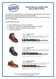
VALVOLA<br />
A COMANDO MANUALE<br />
MANUAL<br />
RELEASE VALVE<br />
CM04<br />
CAVITÀ<br />
CAVITY<br />
2<br />
3<br />
4<br />
Leva + Micro<br />
Lever + Micro<br />
Solo leva<br />
Only lever<br />
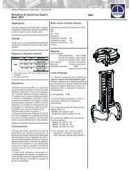
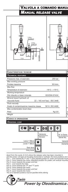
CARATTERISTICHE TECNICHE<br />
TECHNICAL FEATURES<br />
PERDITE DI CARICO<br />
PRESSURE DROPS<br />
Pressione max. di esercizio<br />
250 bar<br />
Max working pressure<br />
Portata massima<br />
30 l/min<br />
Max flow<br />
Temperatura di esercizio<br />
-15°C ÷ +70°C<br />
Working temperature<br />
Olio idraulico a base minerale ISO/DIN 6743/4<br />
Mineral based hydraulic oil<br />
Viscosità fluido 22 ÷ 100 mm 2 /sec - ISO 3448<br />
Fluid viscosity<br />
Grado di contaminazione massimo classe 18/14 ISO 4406<br />
Max contamination level class<br />
Peso Kg 0,8<br />
Weight<br />
∆P - (bar) →<br />
A → B<br />
B → A<br />
Q (l/min) →<br />
Solo valvola (senza cavità)<br />
Valve only (without cavity)<br />
Fluido impiegato: olio minerale con viscosità 45 mm 2 /s a 40°C.<br />
Fluid used: mineral based oil with viscosity 45 mm 2 /s at 40°C.<br />
CODICE DI ORDINAZIONE<br />
ORDERING CODE<br />
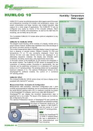
POSIZIONI DI MONTAGGIO<br />
MOUNTING POSITION<br />
CM 04 * 00<br />
0 0<br />
Leva + Micro<br />
Lever + Micro<br />
Solo leva<br />
Only lever<br />
M<br />
L<br />
Versione<br />
Version<br />
N° di Serie<br />
Serial No.<br />
Varianti<br />
Variants<br />
A prescindere dalla cavità (2-3-4) in cui il comando manuale viene montato ed<br />
anche dal tipo di montaggio (orizzontale o verticale) della centralina, le posizioni<br />
della leva risultano essere 8:<br />
Pos. 1 Leva rivolta verso gli attacchi “P” “T” (Standard con centralina orizzontale)<br />
Pos. 2 Leva rivolta il motore (Standard con centralina verticale)<br />
Pos. 3 Leva rivolta verso il piede della centralina<br />
Pos. 4 Leva rivolta verso il motore<br />
Pos. 5 Leva rivolta verso gli attacchi "P" "T"<br />
Pos. 6 Leva rivolta verso il motore<br />
Pos. 7 Leva rivolta verso il piede della centralina<br />
Pos. 8 Leva rivolta verso il motore<br />
Le posizioni di montaggio non standard sono da specificare a parte in fase di<br />
ordinazione.<br />
Apart from the cavity (2-3-4) where the release valve has been mounted in<br />
and the <strong>power</strong> <strong>unit</strong> type of mounting (horizontal or vertical), the lever positions are 8:<br />
Pos 1. Lever towards the “P” and “T” ports (standard position for <strong>power</strong> <strong>unit</strong> horizontal mounting)<br />
Pos 2. Lever towards the motor (standard position for <strong>power</strong> <strong>unit</strong> vertical mounting)<br />
Pos 3. Lever towards the <strong>power</strong> <strong>unit</strong> foot<br />
Pos 4. Lever towards the motor.<br />
Pos 5. Lever towards the "P" and "T" ports<br />
Pos 6. Lever towards the motor<br />
Pos 7. Lever towards the <strong>power</strong> <strong>unit</strong> foot<br />
Pos 8. Lever towards the motor<br />
The out of standard positions must be specified while ordering<br />
3.305.1