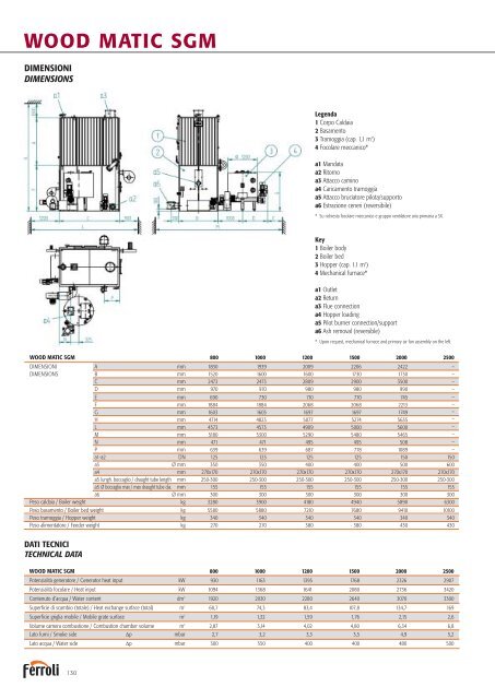
WOOD MATIC SGMDIMENSIONIDIMENSIONSLegenda1 Corpo Caldaia2 Basamento3 Tramoggia (cap. 1,1 m 3 )4 Focolare meccanico*a1 Mandataa2 Ritornoa3 Attacco caminoa4 Caricamento tramoggiaa5 Attacco bruciatore pilota/supportoa6 Estrazione ceneri (reversibile)* Su richiesta focolare meccanico e gruppo ventilatore aria primaria a SX.Key1 Boiler body2 Boiler bed3 Hopper (cap. 1.1 m 3 )4 Mechanical furnace*a1 Outleta2 Returna3 Flue connectiona4 Hopper loadinga5 Pilot burner connection/supporta6 Ash removal (reversible)* Upon request, mechanical furnace and primary air fan assembly on the left.WOOD MATIC SGM 800 1000 1200 1500 2000 2500DIMENSIONI A mm 1830 1939 2009 2206 2422 –DIMENSIONS B mm 1520 1600 1600 1730 1730 –C mm 2473 2473 2809 2900 3500 –D mm 970 970 980 980 990 –E mm 690 730 710 770 745 –F mm 1884 1884 2068 2068 2213 –G mm 1603 1603 1697 1697 1749 –H mm 4714 4823 5077 5274 5635 –L mm 4573 4573 4909 5000 5600 –M mm 5180 5300 5290 5480 5465 –N mm 471 471 495 495 508 –P mm 639 639 687 778 1089 –a1-a2 DN 125 125 125 125 150 150a3 Ø mm 350 350 400 400 500 600a4 mm 270x170 270x170 270x170 270x170 270x170 270x170a5 lungh. boccaglio / draught tube length mm 250-300 250-300 250-300 250-300 250-300 250-300a5 Ø boccaglio max / max draught tube dia. mm 155 155 155 155 155 155a6 Ø mm 300 300 300 300 300 300Peso caldaia / Boiler weight kg 3280 3900 4180 4940 5890 6300Peso basamento / Boiler bed weight kg 5580 5880 7210 7680 9410 10100Peso tramoggia / Hopper weight kg 340 340 340 340 340 340Peso alimentatore / Feeder weight kg 270 270 380 380 430 430DATI TECNICITECHNICAL DATAWOOD MATIC SGM 800 1000 1200 1500 2000 2500Potenzialità generatore / Generator heat input kW 930 1163 1395 1768 2326 2907Potenzialità focolare / Heat input kW 1094 1368 1641 2080 2736 3420Contenuto d’acqua / Water content dm 3 1920 2030 2280 2640 3070 3300Superficie di scambio (totale) / Heat exchange surface (total) m 2 60,7 74,3 83,4 107,8 134,7 169Superficie griglia mobile / Mobile grate surface m 2 1,19 1,32 1,59 1,76 2,15 2,6Volume camera combustione / Combustion chamber volume m 3 2,87 3,14 4,02 4,80 6,34 6,8Lato fumi / Smoke side Δp mbar 2,7 3,2 3,3 3,5 4,9 5,2Lato acqua / Water side Δp mbar 300 350 400 400 480 500130
ACCESSORI A RICHIESTA■ Potenza termica modulata in continuo: permette di ridurrela potenzialità bruciata dal 100 fino al 50%, riducendo alminimo gli spegnimenti della caldaia. La sonda di temperaturadell’acqua di andata agisce sul regolatore a logica programmabileche modifica la velocità della coclea di alimentazione e leportate d’aria comburente mediante inverter che comandano imotori relativi.■ Regolatore di tiraggio: mantiene costante, al valore impostato,il tiraggio in camera di combustione. Consta di strumentorilevatore e farfalla motorizzata sul condotto di by-pass della batteriamulticiclonica oppure inverter sull’aspiratore fumi. Ha unruolo importante nel contenimento delle emissioni di polveri.■ Bruciatore di accensione o pilota: consente di operare inautomatico la prima accensione del combustibile solido ed èindispensabile per materiali con elevata umidità. Di tipo monobloccoad una sola fiamma (~0,25 MW) può essere alimentatoda gasolio o gas metano. Il suo inserimento in caldaia e arretramentopuò essere del tipo automatizzato mediante sistemapneumatico. Nella versione automatica la logica elettrica consenteanche di avvalersi del suo supporto per abbattere ulteriormenteil tenore di CO nei fumi.■ Analizzatore con controllo in continuo: lettura su displaydi: CO - O 2 , temperatura fumi camino (obbligatori secondoDM 05/02/98 per potenze superiori a 1 MW).■ Sistema di registrazione dati sulle emissioni fumi alcamino: il programma Trend View collegato alla caldaia, acquisisce,elabora, calcola e media tutte le informazioni che ricevein continuo e presenta i dati raccolti in formato tabellare secondoquanto richiesto dal D.Lgs. 152/06. Il software va installatosu PC (non fornito) e viene collegato al quadro elettrico conprotocollo ethernet.■ Sistema pulizia ad onda d’urto SBS: riduce la frequenzadella pulizia del fascio tubero e mantiene nel tempo l'efficienzadi scambio termico. Il sistema è composto da una serie disoffiatori ad onda d'urto applicati sulla struttura caldaia, e daun temporizzatore che gestisce il corretto funzionamento. Lepolveri residue della combustione staccate dal banco convettivo,vengono trasportate dal flusso dei fumi e vengono decantatedel sistema di filtrazione a valle della caldaia. Il sistemafunziona con caldaia in marcia.■ Ricircolo fumi in camera di combustione per abbattimentoNOx: il sistema permette di completare la combustionecon una temperatura costante e più bassa rispetto ad unacombustione senza il ricircolo. Resta inteso che per percentualielevate di azoto nel combustibile, anche il ricircolo fumidiventa insufficiente.■ Scala e passerella per l’accesso alle porte di pulizia lateralidal fascio tubiero.ACCESSORIES AVAILABLE ON REQUEST■ Continuous heat output modulation: allows the heatinput to be reduced continuously from 100% to 50% minimisingthe number of boiler shut-downs. A programmable logiccontroller connected to the water outlet temperature probevaries the rotation speeds respectively of the fuel feed screwand the combustion air fans using inverters.■ Draught regulator: this keeps the draught in the combustionchamber constant. It consists of a sensor device and amotor-driven throttle valve on the centrifugal dust separatorassembly bypass duct or the flue gas exhaust inverter. This isimportant in terms of limiting dust emissions.■ Ignition or pilot burner: allows automatic initial ignition ofsolid fuel, essential for materials with a high moisture content.One-piece unit with one flame (~0.25 MW), can operate onoil or natural gas. A pneumatic system automatically controlsits entry into and return out of the boiler. In the automatic version,the electrical logic also allows this to be used for afurther reduction in the CO content of the flue gas.■ Analyser with continuous control: reading on display ofCO - O 2 , flue gas temperature (required by legislation for heatoutputs exceeding 1 MW).■ System for recording data on flue gas emissions: theTrend View program connected to the boiler acquires, processes,calculates and averages out all the information receivedcontinuously, and then provides the data in table form (asrequired by certain legislation). The software must be installedon a PC (not supplied) and is connected to the electricalpanel via Ethernet protocol.■ SBS shockwave cleaning system: this reduces the requiredfrequency for cleaning the tube bundle and ensures the heatexchanger works efficiently over time. The system is made upof a series of shockwave blowers fitted on the boiler structure,and a timer to manage correct operation. The residual dustfrom combustion removed from the tube bundle is carried bythe flue gas and decants in the filtration system downstreamof the boiler. The system works with the boiler operating.■ Flue gas recirculation in the combustion chamber forNOx reduction: the system allows combustion to occur ata constant and lower temperature than combustion withoutrecirculation. Clearly, when there are high percentages ofnitrogen in the fuel, even flue gas recirculation will be insufficient.■ Ladders and walkway to access the side doors for cleaningthe tube bundle.131