Projektierung mit Harmonic Drive Getrieben Engineering Data for ...
Projektierung mit Harmonic Drive Getrieben Engineering Data for ...
Projektierung mit Harmonic Drive Getrieben Engineering Data for ...

Erfolgreiche ePaper selbst erstellen
Machen Sie aus Ihren PDF Publikationen ein blätterbares Flipbook mit unserer einzigartigen Google optimierten e-Paper Software.
<strong>Projektierung</strong> <strong>mit</strong> <strong>Harmonic</strong> <strong>Drive</strong> <strong>Getrieben</strong><br />
<strong>Engineering</strong> <strong>Data</strong> <strong>for</strong> <strong>Harmonic</strong> <strong>Drive</strong> Gears<br />
■■<br />
Antriebsauslegung<br />
■■<br />
Actuator Selection<br />
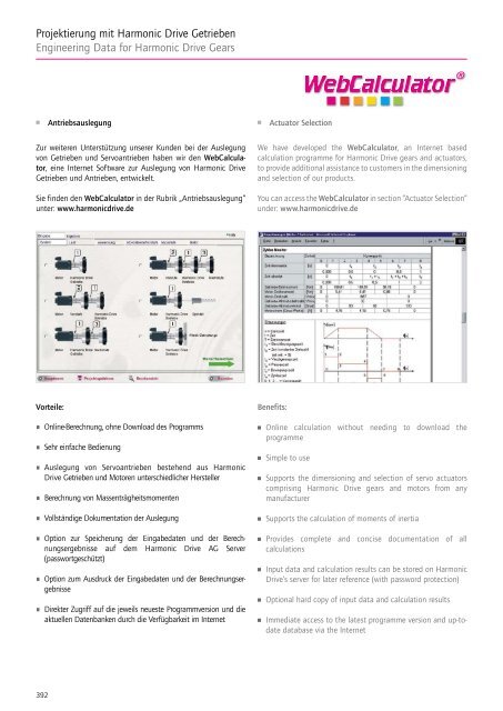
Zur weiteren Unterstützung unserer Kunden bei der Auslegung<br />
von <strong>Getrieben</strong> und Servo antrieben haben wir den WebCalculator,<br />
eine Internet Software zur Auslegung von <strong>Harmonic</strong> <strong>Drive</strong><br />
<strong>Getrieben</strong> und Antrieben, entwickelt.<br />
Sie finden den WebCalculator in der Rubrik „Antriebsauslegung“<br />
unter: www.harmonicdrive.de<br />
We have developed the WebCalculator, an Internet based<br />
calculation programme <strong>for</strong> <strong>Harmonic</strong> <strong>Drive</strong> gears and actuators,<br />
to provide additional assistance to customers in the dimensioning<br />
and selection of our products.<br />
You can access the WebCalculator in section “Actuator Selection“<br />
under: www.harmonicdrive.de<br />
Vorteile:<br />
Online-Berechnung, ohne Download des Programms<br />
Sehr einfache Bedienung<br />
Auslegung von Servoantrieben bestehend aus <strong>Harmonic</strong><br />
<strong>Drive</strong> <strong>Getrieben</strong> und Motoren unterschiedlicher Hersteller<br />
Berechnung von Massenträgheitsmomenten<br />
Vollständige Dokumentation der Auslegung<br />
Option zur Speicherung der Eingabedaten und der Berechnungsergebnisse<br />
auf dem <strong>Harmonic</strong> <strong>Drive</strong> AG Server<br />
(passwortgeschützt)<br />
Option zum Ausdruck der Eingabedaten und der Berechnungsergebnisse<br />
Direkter Zugriff auf die jeweils neueste Programmversion und die<br />
aktuellen Datenbanken durch die Verfügbarkeit im Internet<br />
Benefits:<br />
Online calculation without needing to download the<br />
programme<br />
Simple to use<br />
Supports the dimensioning and selection of servo actuators<br />
comprising <strong>Harmonic</strong> <strong>Drive</strong> gears and motors from any<br />
manufacturer<br />
Supports the calculation of moments of inertia<br />
Provides complete and concise documentation of all<br />
calculations<br />
Input data and calculation results can be stored on <strong>Harmonic</strong><br />
<strong>Drive</strong>‘s server <strong>for</strong> later reference (with password protection)<br />
Optional hard copy of input data and calculation results<br />
Immediate access to the latest programme version and up-todate<br />
database via the Internet<br />
392
<strong>Projektierung</strong> <strong>mit</strong> <strong>Harmonic</strong> <strong>Drive</strong> <strong>Getrieben</strong><br />
<strong>Engineering</strong> <strong>Data</strong> <strong>for</strong> <strong>Harmonic</strong> <strong>Drive</strong> Gears<br />
www.harmonicdrive.de<br />
■■<br />
3D-CAD Modelle zum Download<br />
■■<br />
3D CAD Models <strong>for</strong> Downloading<br />
Als besonderen Service bieten wir unseren Kunden und Interessenten<br />
alle Getriebe und Servoantriebe wahlweise als 2D- oder<br />
3D-CAD Modelle in einer Fülle von gängigen Formaten auf<br />
unseren Internetseiten. Hier lassen sich durch wenige Mausklicks<br />
die gewünschten Produktdateien herunterladen. Sie rufen aus<br />
unserer Website stets die aktuellen Daten ab.<br />
Beim Herunterladen können Sie aus den nachstehenden gängigen<br />
2D- und 3D-Formaten wählen:<br />
As a special service <strong>for</strong> our customers, all gears and servo<br />
actuators are available <strong>for</strong> download from the internet either<br />
as 2D or 3D CAD models, in a variety of common <strong>for</strong>mats. The<br />
desired product data can be downloaded with just a few mouse<br />
clicks. Our website allows you to access the most up-to-date<br />
in<strong>for</strong>mation – and only the in<strong>for</strong>mation you really need.<br />
You can select from the following relevant 2D or 3D <strong>for</strong>mats:<br />
Format 3D<br />
3D <strong>for</strong>mat<br />
BMP<br />
DWG > = R14 (3D)<br />
DXF (3D)<br />
Format 2D<br />
2D <strong>for</strong>mat<br />
DWG, ACAD R12<br />
DWG, ACAD R13<br />
DWG, ACAD R14<br />
IGES (3D) DWG, ACAD 2000<br />
JPEG<br />
PCX<br />
PNG<br />
DXF, ACAD R12<br />
DXF, ACAD R13<br />
DXF, ACAD R14<br />
SAT, ACIS 2.0, 3.0, 4.0, 5.0 DXF, ACAD 2000<br />
STEP AP 203<br />
STEP AP 214<br />
TGA<br />
TIFF<br />
VRML<br />
SVG<br />
393
<strong>Projektierung</strong> <strong>mit</strong> <strong>Harmonic</strong> <strong>Drive</strong> <strong>Getrieben</strong><br />
<strong>Engineering</strong> <strong>Data</strong> <strong>for</strong> <strong>Harmonic</strong> <strong>Drive</strong> Gears<br />
Wir freuen uns, Ihnen in diesem Kapitel ausführliche In<strong>for</strong>mationen<br />
zu unseren Produkten präsentieren zu können. Die in<br />
unserem Katalog gebotenen In<strong>for</strong>mationen sollen Ihnen bei der<br />
Auswahl Ihres Getriebes und den Aufgaben der Maschinenkonstruktion<br />
helfen. Wir sind davon überzeugt, dass der Umfang<br />
und die Qualität der hier dargestellten Daten denen anderer<br />
Getriebehersteller genauso überlegen ist wie die Qualität unserer<br />
Produkte. Selbstverständlich stehen wir Ihnen zur Beantwortung<br />
Ihrer Fragen zur Verfügung. Eine Kontaktliste finden Sie auf der<br />
Rückseite dieses Katalogs oder auf unserer Website. Zögern Sie<br />
bitte nicht, uns anzusprechen.<br />
Die in diesem Katalog wiedergegebenen Werte basieren auf<br />
Messungen, die bei zahlreichen Tests während der Entwicklung<br />
unserer Produkte durchgeführt wurden. Zur Sicherung der<br />
Qualität unserer Produkte erfolgen laufend weitere Tests. Bitte<br />
beachten Sie, dass diese Werte, wie bei allen Messungen, von<br />
Produkt zu Produkt variieren können. Wenn diese Werte für<br />
eine spezifische Anwendung verwendet werden, sollte auch die<br />
Messgenauigkeit dieser Ergebnisse berücksichtigt werden. Soweit<br />
nicht anders angegeben, werden alle Tests, wie in diesem Katalog<br />
beschrieben, <strong>mit</strong> neuen Komponenten bei Normalluftdruck<br />
und -temperatur <strong>mit</strong> Standardschmierung durchgeführt. Die<br />
Ergebnisse können unter verschiedenen Bedingungen erheblich<br />
variieren. Für weitere Details kontaktieren Sie uns bitte.<br />
We are pleased to present detailed in<strong>for</strong>mation about our<br />
products in this chapter. The in<strong>for</strong>mation presented in our<br />
catalogue is designed to help you with your drive selection<br />
and machine design tasks. We consider the amount and quality<br />
of data presented here to be in excess of other drive system<br />
manufacturers – just like the quality of our products. Of course<br />
we are available to answer any questions you may have. You will<br />
find a list of contacts on the back of this catalogue or on our<br />
website. Please feel free to contact us.<br />
The values in this catalogue are based on measurements made<br />
during numerous tests carried out during the development of our<br />
products. Further tests are continually being conducted to ensure<br />
the quality of these products is maintained. Please note that, as<br />
with all measurements, these values can vary from product to<br />
product. When using these values <strong>for</strong> a specific application, the<br />
measuring accuracy <strong>for</strong> these results should also be considered.<br />
When not otherwise stated, all tests are conducted with new<br />
components at standard air pressure and temperature with<br />
standard lubrication as described in this catalogue. Results may<br />
vary considerably under different conditions. For further details,<br />
please contact us.<br />
■■<br />
An- und Abtriebsanordnungen<br />
■■<br />
Driving Arrangements<br />
Mit <strong>Harmonic</strong> <strong>Drive</strong> <strong>Getrieben</strong> sind unterschiedliche An- und<br />
Abtriebsanordnungen möglich.<br />
A variety of different driving arrangements is possible with<br />
<strong>Harmonic</strong> <strong>Drive</strong> gears.<br />
Untersetzung / Ratio i =<br />
Antriebsdrehzahl / Input speed<br />
Abtriebsdrehzahl / Output speed<br />
■■<br />
Überblick <strong>Harmonic</strong> <strong>Drive</strong> Produkte<br />
■■<br />
Overview <strong>Harmonic</strong> <strong>Drive</strong> Products<br />
HFUC-, CPL-, CSG-,<br />
CSD-, HFUS-2A<br />
CPU-M, -H, -S<br />
HFUC-, CSG-2UH<br />
HFUS-2UH, -2S0, -2SH,<br />
SHG-2UH<br />
PMG, CSF Mini<br />
394
<strong>Projektierung</strong> <strong>mit</strong> <strong>Harmonic</strong> <strong>Drive</strong> <strong>Getrieben</strong><br />
<strong>Engineering</strong> <strong>Data</strong> <strong>for</strong> <strong>Harmonic</strong> <strong>Drive</strong> Gears<br />
■■<br />
Untersetzung<br />
■■<br />
Ratio<br />
1) 2) 3)<br />
FS<br />
CS<br />
WG<br />
Untersetzungsgetriebe / Reduction gearing<br />
CS Fixiert / Fixed<br />
WG Antrieb / Input<br />
FS Abtrieb / Output<br />
Untersetzungsgetriebe / Reduction gearing<br />
FS Fixiert / Fixed<br />
WG Antrieb / Input<br />
CS Abtrieb / Output<br />
Untersetzungsgetriebe / Reduction gearing<br />
WG Fixiert / Fixed<br />
FS Antrieb / Input<br />
CS Abtrieb / Output<br />
Untersetzung / Ratio = -<br />
i<br />
1<br />
[Gleichung / Equation 395.1]<br />
Untersetzung / Ratio = i +1<br />
1<br />
Untersetzung / Ratio = i +1<br />
1<br />
[Gleichung / Equation 395.2] [Gleichung / Equation 395.3]<br />
An- und Abtrieb drehen entgegengesetzt.<br />
Input and output rotate in opposite directions.<br />
An- und Abtrieb drehen gleichsinnig.<br />
Input and output rotate in the same direction.<br />
An- und Abtrieb drehen gleichsinnig.<br />
Input and output rotate in the same direction.<br />
4) 5) 6)<br />
Übersetzungsgetriebe / Speed increaser gearing<br />
WG Fixiert / Fixed<br />
CS Antrieb / Input<br />
FS Abtrieb / Output<br />
Übersetzungsgetriebe / Speed increaser gearing<br />
CS Fixiert / Fixed<br />
FS Antrieb / Input<br />
WG Abtrieb / Output<br />
Übersetzungsgetriebe / Speed increaser gearing<br />
FS Fixiert / Fixed<br />
CS Antrieb / Input<br />
WG Abtrieb / Output<br />
Untersetzung / Ratio =<br />
1<br />
i +1<br />
[Gleichung / Equation 395.4]<br />
Untersetzung / Ratio = -<br />
1<br />
i +1<br />
Untersetzung / Ratio =<br />
1<br />
i +1<br />
[Gleichung / Equation 395.5] [Gleichung / Equation 395.6]<br />
An- und Abtrieb drehen gleichsinnig.<br />
Input and output rotate in the same direction.<br />
An- und Abtrieb drehen entgegengesetzt.<br />
Input and output rotate in opposite directions.<br />
An- und Abtrieb drehen gleichsinnig.<br />
Input and output rotate in the same direction.<br />
7)<br />
Differenzialgetriebe / Differential gearing<br />
WG Regelantrieb / Control input<br />
CS Hauptantrieb / Main drive input<br />
FS Hauptabtrieb / Main drive output<br />
Zahlreiche Differenzialfunktionen können durch Kombination<br />
der Drehzahl und Drehrichtung der drei Bauteile<br />
erreicht werden. Weitere In<strong>for</strong>mationen finden<br />
Sie in unserer Broschüre „Differentialanwendungen“,<br />
die Sie von unserer Website herunterladen können.<br />
Numerous differential functions can be obtained by<br />
combinations of the speed and rotational direction<br />
of the three basic elements. Please refer to our<br />
broshure "Differential Applications" available to<br />
download from our website.<br />
395
<strong>Projektierung</strong> <strong>mit</strong> <strong>Harmonic</strong> <strong>Drive</strong> <strong>Getrieben</strong><br />
<strong>Engineering</strong> <strong>Data</strong> <strong>for</strong> <strong>Harmonic</strong> <strong>Drive</strong> Gears<br />
■■<br />
Zahnprofil<br />
■■<br />
Tooth Profile<br />
Die in diesem Katalog beschriebenen Getriebeeinbausätze und<br />
Units werden <strong>mit</strong> der optimierten IH-Ver zah nung gefertigt.<br />
Bei der IH-Verzahnung handelt es sich um ein <strong>Harmonic</strong> <strong>Drive</strong><br />
spezifisches, patentiertes Zahn profil, <strong>mit</strong> dem eine erhebliche<br />
Steigerung der übertragbaren Drehmomente erzielt wird, siehe<br />
Abb. 396.1.<br />
Während bei <strong>Harmonic</strong> <strong>Drive</strong> <strong>Getrieben</strong> <strong>mit</strong> herkömmlicher<br />
Verzahnung etwa 15 % der gesamten Zähnezahl gleichzeitig<br />
im Eingriff sind, liegt dieser Anteil bei der IH-Verzahnung bei<br />
etwa 30 %, siehe Abb. 396.2. Die daraus resultierende geringere<br />
Belastung des Wave Generator Kugellagers führt zu einer<br />
deutlich längeren Lebensdauer des Getriebes. Bemerkenswert ist<br />
die Verdoppelung der Torsionssteifigkeit bei Getrie ben <strong>mit</strong> IH-Verzahnung.<br />
Aus der Vergrößerung des Zahnfuß ra di us im Zahnprofil<br />
resultieren geringere Zahn fuß span nungen, welche eine Erhöhung<br />
der Drehmo ment kapazität zur Folge haben.<br />
Die verbesserten Leis tungsmerkmale der Getriebe <strong>mit</strong> IH-Verzahnung<br />
ermöglichen den Einsatz in hochdynamischen Servo -<br />
systemen, bei denen hohe Torsionssteifigkeit und höchste Drehmomentkapazität<br />
ge<strong>for</strong>dert werden. Diese Getriebe sind spielfrei,<br />
wodurch exzellente Übertragungs- und Wieder ho lge nauigkeiten<br />
erreicht werden.<br />
The <strong>Harmonic</strong> <strong>Drive</strong> Component Sets and Units presented<br />
in this catalogue incorporate “IH“ type gearing. “IH“ type<br />
gearing features a patented tooth profile which provides<br />
a significant improvement in gear operating characteristics<br />
previously considered to be li<strong>mit</strong>ed by the basic <strong>Harmonic</strong> <strong>Drive</strong><br />
gearing principle.<br />
The “IH“ tooth profile, shown in Fig. 396.1, increases the region of<br />
tooth engagement greatly. For the traditional tooth profile about<br />
15 % of the total number of teeth are in contact, whilst <strong>for</strong> the<br />
new profile up to 30 % of the teeth are in contact, as shown in<br />
Fig. 396.2. The increased number of teeth in engagement results<br />
in a considerable increase in torsional stiffness. This tooth profile<br />
also features an enlarged tooth root radius, which results in a<br />
higher allowable stress and a corresponding increase in torque<br />
capacity. Furthermore, the enlarged region of tooth engagement<br />
leads to reduced loading of the Wave Generator bearing, resulting<br />
in a significantly increased life expectancy <strong>for</strong> the gear.<br />
The improved features of the “IH“ type gearing make it an<br />
excellent choice <strong>for</strong> servo applications where high rigidity and<br />
high peak torque capacity are required. The “IH“ type gearing<br />
features zero backlash to offer excellent transmission accuracy<br />
and repeatability.<br />
Abb. / Fig. 396.1 Abb. / Fig. 396.2<br />
Herkömmliche <strong>Harmonic</strong> <strong>Drive</strong> Verzahnung / conventional <strong>Harmonic</strong> <strong>Drive</strong> gearing<br />
IH-Verzahnung / IH type gearing<br />
Zeitlicher Ablauf des Zahneingriffs<br />
Path of tooth engagement<br />
Eingriffsbereich der Verzahnung<br />
Tooth engagement region<br />
396
<strong>Projektierung</strong> <strong>mit</strong> <strong>Harmonic</strong> <strong>Drive</strong> <strong>Getrieben</strong><br />
<strong>Engineering</strong> <strong>Data</strong> <strong>for</strong> <strong>Harmonic</strong> <strong>Drive</strong> Gears<br />
■■<br />
Auslegung von <strong>Harmonic</strong> <strong>Drive</strong> <strong>Getrieben</strong><br />
■■<br />
Selecting <strong>Harmonic</strong> <strong>Drive</strong> Gears<br />
Bei der Auslegung sollten grundsätzlich sowohl Drehmoment- als<br />
auch Steifigkeitsan<strong>for</strong>derungen berücksichtigt werden. Während<br />
z. B. bei Roboter anwendungen eher die er<strong>for</strong>derlichen Drehmomente<br />
ausschlaggebend für die Getriebe bau größe sind, ist im<br />
Werkzeug maschinenbau oft die prozessbedingte Torsionssteifigkeit<br />
entscheidend.<br />
Wir empfehlen daher, immer beide Auslegungs kriterien gemäß<br />
dem folgenden Schema zu berücksichtigen. Alternativ kann die<br />
Getriebe berechnung <strong>mit</strong> dem Berechnung s programm „WebCalculator“<br />
unter www.harmonicdrive.de durchgeführt werden.<br />
When choosing a gear, you should take into account both<br />
torque as well as stiffness requirements. In robot applications,<br />
<strong>for</strong> example, the necessary torque is the more crucial factor <strong>for</strong><br />
the gear size, while the process related torsional stiffness is often<br />
decisive in machine tool manufacture.<br />
We there<strong>for</strong>e recommend that you always take both criteria into<br />
account according to the following procedures. Alternatively, you<br />
can dimension the required gear using the “WebCalculator“ at<br />
www.harmonicdrive.de.<br />
Anwendung<br />
Application<br />
Getriebe Vorauswahl<br />
Gear preselection<br />
Drehmomentbasierte<br />
Auslegung gemäß<br />
Auswahlschema S. 398<br />
Torque based dimensioning<br />
according to selection<br />
procedure on page 398<br />
Auswahl eines<br />
größeren Getriebes<br />
Selection of a<br />
bigger size<br />
Ja / Yes<br />
Getriebegröße<br />
ausreichend?<br />
Gear size<br />
sufficient?<br />
Nein / No<br />
Steifigkeitsbasierte<br />
Auslegung gemäß<br />
Auswahlschema S. 401<br />
Stiffness based dimensioning<br />
according to selection<br />
procedure on page 401<br />
Auswahl eines<br />
größeren Getriebes<br />
Selection of a<br />
bigger size<br />
Ja / Yes<br />
Getriebegröße<br />
ausreichend?<br />
Gear size<br />
sufficient?<br />
Nein / No<br />
Ende der<br />
Getriebeauslegung<br />
End of gear<br />
selection<br />
397
<strong>Projektierung</strong> <strong>mit</strong> <strong>Harmonic</strong> <strong>Drive</strong> <strong>Getrieben</strong><br />
<strong>Engineering</strong> <strong>Data</strong> <strong>for</strong> <strong>Harmonic</strong> <strong>Drive</strong> Gears<br />
■■<br />
Auswahlschema: Drehmomentbasierte Auslegung<br />
■■<br />
Selection Procedure: Torque Based Dimensioning<br />
Belastungsdaten des Abtriebes<br />
Output <strong>Data</strong><br />
Abb. / Fig. 398.1<br />
Drehmomente T 1 ...T n [Nm] Torques T 1 ...T n [Nm]<br />
während der Belastungszeit t 1 ...t n [s] during the load phases t 1 ...t n [s]<br />
während der Pausenzeit t p [s] during the pause time t p [s]<br />
n 1<br />
n 2<br />
Zeit<br />
t 3<br />
T max ≤ T R<br />
T 1<br />
T<br />
Time<br />
1<br />
Emergency stop/<br />
Not-Stopp / Kollisionsmoment T k [Nm]<br />
T<br />
momentary peak torque k [Nm]<br />
T 2<br />
und Abtriebsdrehzahl n 1 ...n n [min -1 ] and output speeds n 1 ...n n [rpm]<br />
t 1<br />
t 2<br />
t p<br />
t 1<br />
n p<br />
HFUC: L 50 = L n<br />
* · Nenn-Antriebsdrehzahl · ( Nennmoment ) TN 3<br />
n in av T av<br />
HFUC: L 50 = L n<br />
* · Rated input speed · ( Rated torque ) TN 3<br />
n in av T av<br />
bei Abtriebsdrehzahl n k [min -1 ] at output speed n k [rpm]<br />
T 3<br />
Zeit / Time<br />
während der Zeit t k [s] and duration t k [s]<br />
Belastungsgrenze 1,<br />
Load li<strong>mit</strong> 1,<br />
Er<strong>mit</strong>tlung des durchschnittlichen Abtriebsdrehmomentes T av<br />
calculation of the average output torque T av<br />
3<br />
|n 1 · T 13 | · t +|n · T 1 2 2 3 | · t + ... + 2 |nn · Tn3 | · t n<br />
T av =<br />
|n 1 | · t 1 +|n 2 | · t 2 + ... + |nn| · tn<br />
[Gleichung / Equation 398.2]<br />
Werte für T A siehe Leistungsdatentabelle<br />
Values <strong>for</strong> T A see rating tables Nein<br />
Auswahl eines größeren<br />
No<br />
T av ≤ T A<br />
Getriebes<br />
[Gleichung / Equation 398.3]<br />
Selection of a bigger size<br />
Berechnung der durchschnittlichen<br />
Durchschnittliche<br />
Calculation of the average output speed<br />
Abtriebsdrehzahl<br />
Antriebsdrehzahl<br />
Average input speed<br />
n out av =<br />
|n 1 |· t 1 + |n 2 | · t + ... + |n 2 n| · t n<br />
n in av = i · n out av<br />
t 1 + t + ... + t + t 2 n p<br />
[Gleichung / Equation 398.4]<br />
[Gleichung / Equation 398.5]<br />
Zulässige maximale Antriebsdrehzahl Permissible maximum input speed<br />
Zulässige <strong>mit</strong>tlere Permissible average<br />
Antriebsdrehzehl<br />
input speed<br />
n in max = n out max · i ≤ Maximale Antriebsdrehzahl (s. Leistungsdatentabelle) /<br />
Maximum input speed (see rating table)<br />
[Gleichung / Equation 398.6]<br />
n in av ≤ Grenze für <strong>mit</strong>tlere Antriebsdrehzahl<br />
(s. Leistungsdatentabelle) / Li<strong>mit</strong> <strong>for</strong> average input speed<br />
(s. rating table)<br />
[Gleichung / Equation 398.7]<br />
Belastungsgrenze 2, T R Load li<strong>mit</strong> 2, T R Belastungsgrenze 3, T M Load li<strong>mit</strong> 3, T M<br />
Erlaubte Anzahl von Allowable number of<br />
Kollisionsmomenten momentary peak torques<br />
N k max = 10 4<br />
T k ≤ T M<br />
2· nk [min -1 ]·i·tk [s]<br />
60<br />
[Gleichung / Equation 398.8]<br />
[Gleichung / Equation 398.9]<br />
[Gleichung / Equation 398.10]<br />
Lebensdauer Operating life<br />
* L n siehe Kapitel „Lebensdauer des Wave Generator Kugellagers“ * L n see section “Life of the Wave Generator Bearing“<br />
Drehzahl<br />
Speed<br />
Drehmoment<br />
Torque<br />
n 3<br />
n 1<br />
[Gleichung / Equation 398.11]<br />
398
<strong>Projektierung</strong> <strong>mit</strong> <strong>Harmonic</strong> <strong>Drive</strong> <strong>Getrieben</strong><br />
<strong>Engineering</strong> <strong>Data</strong> <strong>for</strong> <strong>Harmonic</strong> <strong>Drive</strong> Gears<br />
■■<br />
Auslegungsbeispiel: Drehmomentbasierte Auslegung<br />
■■<br />
Selection Example: Torque Based Dimensioning<br />
Belastungsdaten am Abtrieb<br />
Output <strong>Data</strong><br />
T 1 = 400 Nm t 1 = 0,3 s n 1 = 7 min -1 T 1 = 400 Nm t 1 = 0,3 s n 1 = 7 rpm<br />
T 2 = 320 Nm t 2 = 3,0 s n 2 = 14 min -1 T 2 = 320 Nm t 2 = 3,0 s n 2 = 14 rpm<br />
T 3 = 200 Nm t 3 = 0,4 s n 3 = 7 min -1 T 3 = 200 Nm t 3 = 0,4 s n 3 = 7 rpm<br />
T k = 500 Nm t k = 0,15 s n k = 14 min -1 T K = 500 Nm t k = 0,15 s n k = 14 rpm<br />
t p = 0,2 s n p = 0 min -1 t p = 0,2 s n p = 0 rpm<br />
Untersetzung i = 120 Ratio i = 120<br />
Lebensdauer L 50 = 30000 h (ge<strong>for</strong>dert)<br />
Life L 50 = 30000 h (required)<br />
Belastungsgrenze 1,<br />
Er<strong>mit</strong>tlung des durchschnittlichen Abtriebsdrehmomentes T av<br />
Load li<strong>mit</strong> 1,<br />
calculation of the average output torque T av<br />
3<br />
7 min -1 · (400 Nm) 3 · 0,3 s + 14 min -1 · (320 Nm) 3 · 3 s + 7 min -1 · (200 Nm) 3 · 0,4 s<br />
T av =<br />
7 min -1 · 0,3 s + 14 min -1 · 3 s + 7 min -1 · 0,4 s<br />
T av = 319 Nm ≤ T A = 451 Nm<br />
Ausgewähltes Getriebe<br />
Selected size<br />
HFUC-40-120-2A-GR<br />
Berechnung der durchschnittlichen<br />
Abtriebsdrehzahl<br />
Calculation of the average<br />
output speed<br />
Durchschnittliche<br />
Antriebsdrehzahl<br />
Average input speed<br />
n out av = 7 min-1 · 0,3 s + 14 min -1 · 3 s + 7 min -1 · 0,4 s =12,0 min<br />
-1<br />
0,3 s + 3 s + 0,4 s + 0,2 s<br />
n in av = 120 · 12,0 min -1 = 1440 min -1<br />
Zulässige maximale Antriebsdrehzahl Permissible maximum input speed Zulässige <strong>mit</strong>tlere Antriebsdrehzahl Permissible average input speed<br />
n in max = 14 min -1 · 120 = 1680 min -1 ≤ 5600 min -1 n in av = 1440 min -1 ≤ 3600 min -1<br />
(Getriebe <strong>mit</strong> Ölschmierung) (Oil lubricated gear) (Getriebe <strong>mit</strong> Ölschmierung) (Oil lubricated gear)<br />
Belastungsgrenze 2, Load li<strong>mit</strong> 2,<br />
Belastungsgrenze 3, Load li<strong>mit</strong> 3,<br />
T R T R T M T M<br />
Zulässige Anzahl von<br />
Kollisionsmomenten<br />
Allowable number of<br />
momentary peak torques<br />
T max = 400 Nm ≤ T R = 617 Nm<br />
T k = 500 Nm ≤ T M = 1180 Nm<br />
N k max = 104<br />
= 1190<br />
14 min -1 · 120<br />
2 · 60 · 0,15 s<br />
Lebensdauer<br />
Operating life<br />
HFUC-40-120-2A-GR: L 50 = 35000 h · 2000 min-1 · ( 294 Nm ) 3<br />
1440 min -1 319 Nm<br />
L 50 = 38054 h > 30000 h<br />
min -1 = ^ rpm<br />
Wir übernehmen gerne Ihre Getriebeauslegung in unserem Hause.<br />
Bitte kontaktieren Sie unsere Anwendungsberater.<br />
We will be pleased to make a gear calculation and selection<br />
on your behalf. Please contact our application engineers.<br />
399
<strong>Projektierung</strong> <strong>mit</strong> <strong>Harmonic</strong> <strong>Drive</strong> <strong>Getrieben</strong><br />
<strong>Engineering</strong> <strong>Data</strong> <strong>for</strong> <strong>Harmonic</strong> <strong>Drive</strong> Gears<br />
■■<br />
Auswahlschema: Steifigkeitsbasierte Auslegung<br />
■■<br />
Selection Procedure: Stiffness Based Dimensioning<br />
Zusätzlich zu dem auf Seite 398-399 angegebenen Auswahlschema:<br />
„Drehmomentbasierte Auslegung“ empfehlen wir<br />
die Durchführung einer steifigkeitsbasierten Aus legung. Dafür<br />
sollten die in Tabelle 400.1 angegebenen Kenngrößen für die<br />
anwendungsspezifisch empfohlenen Resonanzfrequenzen berücksichtigt<br />
werden.<br />
In addition to the “Selection Procedure: Torque Based<br />
Dimensioning“ stated on Page 398-399, we recommend that<br />
you carry out a selection based on stiffness. For this, the<br />
values provided in Table 400.1 <strong>for</strong> the individual resonance<br />
frequencies recommended <strong>for</strong> each application should be taken<br />
into account.<br />
Tabelle / Table 400.1<br />
Anwendung Application f n [Hz]<br />
Langsam drehende Drehtische, langsam drehende Schweißroboter<br />
Grundachsen (kein Laserschweißen), langsam drehende Schweiß- und<br />
Schwenktische, Palettierroboter-Achsen<br />
Slowly rotating turntables, base axes of slow moving welding robots<br />
(not laser welding), slowly rotating welding and swinging tables,<br />
gantry robot axes<br />
≥ 4<br />
Knickarmroboter Grundachsen, Knickarmroboter Handachsen <strong>mit</strong><br />
geringen Dynamikan<strong>for</strong>derungen, Werkzeugrevolver, Werkzeugmagazine,<br />
Schwenk- und Positionierachsen in medizinischen Geräten und<br />
Messgeräten<br />
Standard Anwendungen im allgemeinen Maschinenbau, Schwenkachsen,<br />
Palettenwechsler, hochdynamische Werkzeugwechsler, -revolver,<br />
und -magazine, Knickarmroboter Handachsen, Scara Roboter, Portalroboter,<br />
Polierroboter, Dynamische Schweißwender, Schweißroboter<br />
Grundachsen (Laserschweißen), Schwenk- und Positionierachsen in<br />
medizinischen Geräten<br />
B/C-Achsen in 5-Achs Schleifmaschinen, Schweißroboter Handachsen<br />
(Laserschweißen), Fräsköpfe Kunststoffbearbeitung<br />
C-Achsen in Drehmaschinen, Fräsköpfe Leichtmetallbearbeitung,<br />
Fräsköpfe Holzbearbeitung (Spanplatten etc.)<br />
Base axes of revolute robots, hand axes of revolute robots with low<br />
requirements regarding dynamic perfomance, tool revolvers, tool<br />
magazines, swivelling and positioning axes in medical and measuring<br />
devices<br />
Standard applications in general mechanical engineering, tilting<br />
axes, palette changers, highly dynamic tool changers, -revolvers and<br />
-magazines, hand axes of revolute robots, scara robots, gantry robots,<br />
polishing robots, dynamic welding manipuators, base axes of welding<br />
robots (laser welding), swivelling and positioning axes of medical<br />
equipment<br />
B/C axes in 5 axis grinding machines, hand axes of welding robots<br />
(laser welding), milling heads <strong>for</strong> plastics machining<br />
C axes in turning machines, milling heads <strong>for</strong> light metal machining,<br />
milling heads <strong>for</strong> woodworking (chipboards etc.)<br />
≥ 8<br />
≥ 15<br />
≥ 20<br />
≥ 25<br />
Fräsköpfe Holzbearbeitung (Hartholz etc.) Milling heads <strong>for</strong> woodworking (hardwood etc.) ≥ 30<br />
C-Achsen in Drehmaschinen* C axes in turning machines* ≥ 35<br />
Fräsköpfe für Metallbearbeitung*, B-Achsen in Dreh-Fräszentren für<br />
Metallbearbeitung<br />
Fräsköpfe für Metallbearbeitung*, B-Achsen in Dreh-Fräszentren für<br />
Metallbearbeitung <strong>mit</strong> hohen An<strong>for</strong>derungen an die Oberflächenqualität*<br />
Fräsköpfe für Metallbearbeitung <strong>mit</strong> sehr hohen An<strong>for</strong>derungen an die<br />
Oberflächenqualität*<br />
Milling heads <strong>for</strong> metal machining*, B axes in turning milling centers<br />
<strong>for</strong> metal machining<br />
Milling heads <strong>for</strong> metal machining*, B axes in turning milling<br />
centers <strong>for</strong> metal machining with high requirements regarding surface<br />
quality*<br />
Milling heads <strong>for</strong> metal machining with very high requirements<br />
regarding surface quality*<br />
≥ 40<br />
≥ 50<br />
≥ 60<br />
* Je nach Anwendung kann eine nachgeschaltete Getriebestufe sinnvoll<br />
sein. Wir empfehlen Rücksprache <strong>mit</strong> der <strong>Harmonic</strong> <strong>Drive</strong> AG.<br />
* Depending on the application, a secondary gear stage may be useful.<br />
Please contact <strong>Harmonic</strong> <strong>Drive</strong> AG <strong>for</strong> more in<strong>for</strong>mation.<br />
400
<strong>Projektierung</strong> <strong>mit</strong> <strong>Harmonic</strong> <strong>Drive</strong> <strong>Getrieben</strong><br />
<strong>Engineering</strong> <strong>Data</strong> <strong>for</strong> <strong>Harmonic</strong> <strong>Drive</strong> Gears<br />
■■<br />
Auslegungsbeispiel: Steifigkeitsbasierte Auslegung<br />
■■<br />
Selection Example: Stiffness Based Dimensioning<br />
Resonanzfrequenz (Getriebeabtrieb)<br />
Resonance Frequency (Gear Output)<br />
Mit der Formel f n =<br />
1 K 1<br />
[Hz]<br />
The <strong>for</strong>mula f n =<br />
1 K 1<br />
[Hz]<br />
2<br />
. J 2 J<br />
f n = Resonanzfrequenz [Hz]<br />
K 1 = Getriebe Torsionssteifigkeit K 1 [Nm/rad]<br />
J = Massenträgheitsmoment der Last [kgm 2 ]<br />
f n = Resonance frequency [Hz]<br />
K 1 = Gear torsional stiffness K 1 [Nm/rad]<br />
J = Load moment of inertia [kgm 2 ]<br />
kann bei gegebener Torsionssteifigkeit K 1 des <strong>Harmonic</strong> <strong>Drive</strong><br />
Getriebes und dem Massenträgheitsmoment der Last die abtriebsseitige<br />
Resonanzfrequenz berechnet werden. Die berechnete Frequenz<br />
sollte dem in Tabelle 400.1 angegebenen Wert entsprechen.<br />
Mit steigendem Massenträgheitsmoment der Last steigt auch der<br />
Einfluss der Anwendung auf das Auslegungsergebnis. Wenn das<br />
Massenträgheitsmoment = 0 ist, hat die gewählte Anwendung<br />
keinen rechnerischen Einfluss auf das Auslegungsergebnis.<br />
Resonanzdrehzahl (Getriebeeingang)<br />
Die Resonanzdrehzahl n n der Antriebsseite (Motorseite) kann <strong>mit</strong><br />
der Formel<br />
n n = f n *30 [min -1 ]<br />
berechnet werden. Wir empfehlen, die Resonanzdrehzahl im Betrieb<br />
zügig zu durchfahren. Dies kann durch die Wahl einer geeigneten<br />
Getriebeuntersetzung erfolgen. Eine andere Möglichkeit ist die Wahl<br />
einer geeigneten Getriebesteifigkeit, so dass die Resonanzdrehzahl<br />
außerhalb des ge<strong>for</strong>derten Drehzahlbereichs liegt.<br />
Auslegungsbeispiel<br />
HFUC-40-120-2A-GR vorausgewählt aus „Auswahlschema: Drehmomentbasierte<br />
Auslegung“ auf Seite 398.<br />
Geplante Anwendung: Fräskopf Holzbearbeitung<br />
Abtriebsseitiges Massenträgheitsmoment: 7 kgm 2<br />
Empfohlene Resonanzfrequenz aus Tabelle 400.1: ≥ 30 Hz.<br />
Resonanzfrequenz <strong>mit</strong> dem vorausgewählten Getriebe<br />
HFUC-40-120-2A-GR:<br />
f n =<br />
1 . 1,3 . 10 5<br />
= 22 [Hz]<br />
2 7<br />
Gemäß steifigkeitsbasierter Auslegung ist diese Baugröße für die<br />
Anwendung zu klein.<br />
Mit dem größeren Getriebe HFUC-50-120-2A-GR ergibt sich die<br />
Resonanzfrequenz:<br />
f n =<br />
1 . 2,5 . 10 5<br />
= 30 [Hz]<br />
2 7<br />
Aufgrund der steifigkeitsbasierten Auslegung wird das Getriebe<br />
HFUC-50-120-2A-GR empfohlen.<br />
Die Resonanzdrehzahl am Antrieb (Motor) beträgt :<br />
n n = 30*30 = 900 [1/min]<br />
Diese Drehzahl sollte während dem Beschleunigen / Bremsen<br />
zügig durchfahren werden oder außerhalb des genutzten Drehzahlbereichs<br />
liegen.<br />
allows you to calculate the resonance frequency at the gear<br />
output from the given torsional stiffness K 1 of the <strong>Harmonic</strong> <strong>Drive</strong><br />
gear and the load‘s moment of inertia. The calculated frequency<br />
should correspond with the value provided in Table 400.1. The<br />
higher the load‘s moment of inertia, the more influence the<br />
application has on the gear selection. If the moment of inertia = 0,<br />
the selected application has no numerical influence on the<br />
selection result.<br />
Resonance Speed (Gear Input)<br />
The resonance speed n n on the input side (motor side) can be<br />
calculated using the <strong>for</strong>mula<br />
n n = f n *30 [rpm]<br />
During operation, we recommend that you pass the resonance<br />
speed rapidly. This can be achieved by selecting a suitable gear<br />
ratio. Another possibility is to select suitable gear stiffness such<br />
that the resonance speed lies beyond the required speed range.<br />
Selection Example<br />
HFUC-40-120-2A-GR preselected from “Selection Procedure:<br />
Torque Based Dimensioning“ on page 398.<br />
Intended application: milling head <strong>for</strong> woodworking<br />
Moment of inertia at the gear output: 7 kgm 2<br />
Recommended resonance frequency from Table 400.1: ≥ 30 Hz.<br />
Resonance frequency using the preselected gear<br />
HFUC-40-120-2A-GR:<br />
f n =<br />
1 . 1,3 . 10 5<br />
= 22 [Hz]<br />
2 7<br />
According to stiffness based dimensioning, this gear size is too<br />
small <strong>for</strong> the application.<br />
The larger gear HFUC-50-120-2A-GR results in a resonance<br />
frequency of:<br />
f n =<br />
1 . 2,5 . 10 5<br />
= 30 [Hz]<br />
2 7<br />
Based on stiffness based dimensioning, the gear HFUC-50-120-<br />
2A-GR is recommendable.<br />
The resonance speed at the input (motor) amounts to:<br />
n n = 30*30 = 900 [rpm]<br />
Either, this speed should be passed without stopping when<br />
accelerating / braking, or it should lie beyond the utilised speed<br />
range.<br />
401
<strong>Projektierung</strong> <strong>mit</strong> <strong>Harmonic</strong> <strong>Drive</strong> <strong>Getrieben</strong><br />
<strong>Engineering</strong> <strong>Data</strong> <strong>for</strong> <strong>Harmonic</strong> <strong>Drive</strong> Gears<br />
■■<br />
Hinweise zu den Leistungsdaten<br />
■■<br />
How to use the Rating Table<br />
Nenndrehmoment (T N )<br />
Das Nenndrehmoment ist ein Referenzdrehmoment für die<br />
Berechnung der Getriebelebensdauer. Bei Belastung <strong>mit</strong> dem<br />
Nenndrehmoment und der Nenndrehzahl erreicht das Getriebe<br />
die <strong>mit</strong>tlere Lebensdauer L 50 . Dieses Referenzdrehmoment wird<br />
nicht für die Dimensionierung angewendet.<br />
Grenze für das Durchschnittsdrehmoment (T A ) – Belas tungsgrenze 1<br />
Wird das Getriebe <strong>mit</strong> wechselnden Lasten beauf schlagt, so sollte<br />
<strong>mit</strong>tels Gleichung 398.2 das durch schnittliche Dreh moment<br />
berechnet werden. Dieser Wert sollte den in den Leistungsdaten<br />
(Tabellen) ange gebenen Grenzwert T A nicht über schrei ten.<br />
Grenze für das Spitzendrehmoment (T R ) – Belas tungsgrenze 2<br />
Der Grenzwert T R gibt die maximal zulässigen Be schleunigungsund<br />
Brems dreh momente an. Das beim Beschleunigen oder Bremsen<br />
auftretende Spit zen dreh moment lässt sich er<strong>mit</strong>teln, wenn<br />
neben dem Lastdrehmoment das Massen trägheitsmoment und<br />
die Beschleu nigungszeit bzw. Bremszeit bekannt sind. Während<br />
des nor ma len Arbeitszyklus sollte der Grenzwert T R nicht überschritten<br />
werden.<br />
Grenze für das Kollisionsdrehmoment (T M ) – Belas tungs grenze 3<br />
Im Falle einer Not-Ausschaltung oder einer Kollision kann das<br />
<strong>Harmonic</strong> <strong>Drive</strong> Getriebe <strong>mit</strong> einem kurzzei ti gen Spitzendrehmoment<br />
beaufschlagt werden. Die An zahl und die Höhe dieses<br />
Spitzendrehmomentes sollten möglichst gering sein. Unter keinen<br />
Umstän den sollte dieses Spitzendrehmoment während des norma<br />
len Arbeitszyklus erreicht werden. Die er laubte An zahl von<br />
Kollisionsdrehmomenten kann <strong>mit</strong> der im Auswahlschema angegebenen<br />
Gleichung berechnet werden.<br />
Rated Torque (T N )<br />
The rated torque is a reference torque <strong>for</strong> the calculation of the<br />
gear lifetime. When loaded with the rated torque and running at<br />
rated speed the gear will achieve the L 50 mean life. This reference<br />
torque is not used <strong>for</strong> dimensioning the gear.<br />
Li<strong>mit</strong> <strong>for</strong> Average Torque (T A ) – Load Li<strong>mit</strong> 1<br />
When the gear is used under a variable load, an average torque<br />
should be calculated <strong>for</strong> the complete operating cycle (see<br />
equation 398.2). The value calculated should not exceed the<br />
li<strong>mit</strong> T A given in the rating table. Otherwise the per <strong>for</strong> mance and<br />
life of the gear will be im paired.<br />
Li<strong>mit</strong> <strong>for</strong> Repeated Peak Torque (T R ) – Load Li<strong>mit</strong> 2<br />
This is the allowable output torque that can be developed during<br />
acceleration or deceleration. The peak torque that occurs during<br />
starting or stopping can be calculated if the static load, load<br />
moment of inertia and acceleration (or deceleration) time are<br />
known. This torque li<strong>mit</strong> must not be exceeded during the normal<br />
operating cycle.<br />
Li<strong>mit</strong> <strong>for</strong> Momentary Peak Torque (T M ) – Load Li<strong>mit</strong> 3<br />
<strong>Harmonic</strong> <strong>Drive</strong> gearing may be subjected to momen tary<br />
peak torques in the event of a collision or emer gency stop.<br />
The magnitude and frequency of occur rence of such peak<br />
torques must be kept to a minimum and they should under<br />
no circumstance occur du ring the normal operating cycle. The<br />
allowable number of momentary peak torques can be calculated<br />
with the equation given in the selection procedure.<br />
402
<strong>Projektierung</strong> <strong>mit</strong> <strong>Harmonic</strong> <strong>Drive</strong> <strong>Getrieben</strong><br />
<strong>Engineering</strong> <strong>Data</strong> <strong>for</strong> <strong>Harmonic</strong> <strong>Drive</strong> Gears<br />
■■<br />
Erläuterungen zu den Technischen Daten<br />
■■<br />
Understanding the Technical <strong>Data</strong><br />
Die Definitionen von technischen Daten können je nach Getriebehersteller<br />
und Produkt variieren. Wir empfehlen, beim Vergleich von<br />
technischen Daten grundsätzlich die jeweils zu Grunde liegenden<br />
Definitionen zu beachten.<br />
Beispiele für Definitionen<br />
1. Leistungsdaten<br />
Unsere Leistungsdaten beinhalten einen Sicherheitsfaktor, der vereinfachende<br />
Annahmen des Anwenders bei der Festlegung von Last und<br />
Zyklus berücksichtigt.<br />
Die Grenze für das wiederholbare Spitzendrehmoment, d. h. das<br />
maximal zulässige Beschleunigungsmoment, liegt unterhalb des<br />
Zeitfestigkeitsbereichs des Flexsplines, s. Abb. 403.1. Das Beschleunigungsmoment<br />
ist so<strong>mit</strong> unabhängig von der Anzahl der Zyklen.<br />
Die Vorteile in der Praxis:<br />
Die im Katalog definierten Leistungsdaten können direkt für<br />
Vergleichszwecke herangezogen werden. Es ist nicht er<strong>for</strong>derlich,<br />
das Beschleunigungsdrehmoment zur Berücksichtigung der Zyklenzahl<br />
zu reduzieren.<br />
Bei einer nachträglichen Erhöhung der bei der ursprünglichen<br />
Auslegung definierten Zyklenzahl verliert die <strong>Harmonic</strong> <strong>Drive</strong><br />
Auslegung nicht ihre Gültigkeit (vorausgesetzt, dass die Grenzen<br />
für wiederholbares Spitzendrehmoment und Durchschnittsdrehmoment<br />
berücksichtigt werden).<br />
The definitions used when specifying technical data can differ<br />
between manufacturers and products. When comparing data we<br />
recommend that you refer to the given definitions.<br />
Examples <strong>for</strong> Definitions<br />
1. Per<strong>for</strong>mance <strong>Data</strong><br />
Our per<strong>for</strong>mance data include a safety margin to reflect the fact<br />
that the user may need to make assumptions regarding load and<br />
duty cycle.<br />
The li<strong>mit</strong> <strong>for</strong> repeated peak torque, typically the li<strong>mit</strong> <strong>for</strong><br />
acceleration torque, lies below the fatigue li<strong>mit</strong> of the Flexspline<br />
(see Fig. 403.1). The li<strong>mit</strong> <strong>for</strong> acceleration torque is there<strong>for</strong>e<br />
independent of the number of cycles.<br />
The practical advantages are as follows:<br />
The per<strong>for</strong>mance data given in the catalogue can be used<br />
directly <strong>for</strong> comparative purposes. There is no need to reduce<br />
the torque li<strong>mit</strong> to reflect the number of cycles.<br />
The selection of a <strong>Harmonic</strong> <strong>Drive</strong> gear does not lose its validity<br />
should the number of operating cycles increase relative to the<br />
initial specification (Assuming that the li<strong>mit</strong>s <strong>for</strong> repeated<br />
peak torque and average torque are not exceeded).<br />
Abb. / Fig. 403.1<br />
Normiertes Lastmoment [Nenndrehmoment T N = 1]<br />
Normalised load torque [Rated torque T N = 1]<br />
18<br />
17<br />
Grenze für Buckling Drehmoment / Li<strong>mit</strong> <strong>for</strong> buckling torque<br />
16<br />
10 ~ ~<br />
9<br />
Grenze für Ratcheting Drehmoment / Li<strong>mit</strong> <strong>for</strong> ratcheting torque<br />
8<br />
7<br />
6<br />
5<br />
Wave Generator Lebensdauer L 10 / Wave Generator L 10 life<br />
Grenze für Flexspline Zahnfußfestigkeit / Fatigue li<strong>mit</strong> <strong>for</strong> Flexspline tooth root<br />
Grenze für Kollisionsmoment / Li<strong>mit</strong> <strong>for</strong> momentary peak torque<br />
4<br />
3<br />
2<br />
1<br />
Grenze für wiederholbares Spitzendrehmoment / Li<strong>mit</strong> <strong>for</strong> repeated peak torque<br />
Nenndrehmoment / Rated torque<br />
0<br />
10 5 10 6 10 7 10 8 10 9 10 10<br />
Anzahl Wave Generator Umdrehungen / Number of Wave Generator revolutions<br />
Das in Abb. 403.1 gezeigte Referenzdiagramm kann in Abhängigkeit von der<br />
Baugröße und Untersetzung variieren. Fettalterung und Verschleißeffekte sind<br />
nicht berücksichtigt. Die Grenze für wiederholbares Spitzendrehmoment darf nur<br />
im Kollisionsfall überschritten werden.<br />
The reference diagram shown in Fig. 403.1 can vary <strong>for</strong> different gear sizes and<br />
reduction ratios. Lubricant ageing effects and general wear are not considered.<br />
The fatigue li<strong>mit</strong> may only be exceeded in the event of a collision.<br />
403
<strong>Projektierung</strong> <strong>mit</strong> <strong>Harmonic</strong> <strong>Drive</strong> <strong>Getrieben</strong><br />
<strong>Engineering</strong> <strong>Data</strong> <strong>for</strong> <strong>Harmonic</strong> <strong>Drive</strong> Gears<br />
2. Torsionssteifigkeit<br />
Einige Getriebe- und Antriebshersteller ignorieren bei der Definition<br />
der Torsionssteifigkeit den Bereich kleiner Drehmomente<br />
(niedriger als T 1 gem. Abb. 404.1). In diesem Bereich ist die<br />
Torsionssteifigkeit im Allgemeinen geringer.<br />
Dies führt dazu, dass die angegebene Torsionssteifigkeit anderer<br />
Getriebehersteller im Allgemeinen <strong>mit</strong> den K 2 oder K 3 Steifigkeiten<br />
der <strong>Harmonic</strong> <strong>Drive</strong> Getriebe zu vergleichen sind. Auch<br />
beim Vergleich von <strong>Harmonic</strong> Planetengetrieben <strong>mit</strong> <strong>Harmonic</strong><br />
<strong>Drive</strong> <strong>Getrieben</strong> sind seitens der <strong>Harmonic</strong> <strong>Drive</strong> Getriebe die K 2<br />
oder K 3 Steifigkeiten heranzuziehen.<br />
Die Steifigkeitswerte und der Torsionswinkel, die sich unter Belastung<br />
ergeben, unterliegen aufgrund der realen Prüfbedingungen<br />
und des Istwerts der Lost Motion des Getriebes Schwankungen<br />
in der Kundenanwendung. Um weitere Details zu erfahren, sprechen<br />
Sie uns bitte an.<br />
2. Torsional Stiffness<br />
Some gear and actuator manufacturers choose to ignore the low<br />
torque range (below T 1 as shown in Fig. 404.1), when defining<br />
torsional stiffness. The torsional stiffness is often lower in this<br />
range.<br />
As a result the torsional stiffness values given by other<br />
manufacturers usually correspond to the K 2 or K 3 values given<br />
<strong>for</strong> the <strong>Harmonic</strong> <strong>Drive</strong> gear. This also applies when comparing<br />
<strong>Harmonic</strong> Planetary Gears and <strong>Harmonic</strong> <strong>Drive</strong> Gears.<br />
Stiffness values and the torsion angle that results under load<br />
are subject to variations due to the actual test conditions and<br />
the actual value <strong>for</strong> lost motion of the gear in the customer<br />
application. For further details, please contact us.<br />
Abb. / Fig. 404.1<br />
Die Torsionssteifigkeit von <strong>Harmonic</strong> <strong>Drive</strong> <strong>Getrieben</strong> bezieht<br />
sich auf drei Abschnitte des unteren Astes der Hysteresekurve<br />
(Drehmoment-Verdrehwinkel) im ersten Quadrant. Der Bereich<br />
kleiner Drehmomente ist bei der Definition der K 1 Torsionssteifigkeit<br />
eingeschlossen.<br />
The torsional stiffness values <strong>for</strong> <strong>Harmonic</strong> <strong>Drive</strong> gears correspond<br />
to three sections of the hysteresis curve (torque-torsion curve) in<br />
the first quadrant. The low torque range is covered by the K 1<br />
spring rate value.<br />
Abb. / Fig. 404.2<br />
Wie bei Planetengetrieben üblich, ist der Bereich kleiner Drehmomente<br />
der Hysteresekurve bei der Definition der Torsionssteifigkeit<br />
von <strong>Harmonic</strong> Planetengetrieben ausgeschlossen.<br />
As is typical <strong>for</strong> planetary gears the low torque portion of the<br />
hysteresis curve is not described in the definition of torsional<br />
stiffness <strong>for</strong> <strong>Harmonic</strong> Planetary Gears.<br />
404
<strong>Projektierung</strong> <strong>mit</strong> <strong>Harmonic</strong> <strong>Drive</strong> <strong>Getrieben</strong><br />
<strong>Engineering</strong> <strong>Data</strong> <strong>for</strong> <strong>Harmonic</strong> <strong>Drive</strong> Gears<br />
Abb. / Fig. 405.1<br />
Andere Hersteller definieren zwei Steifigkeitsbereiche, meist<br />
ebenfalls unter Ausschluss des Bereichs geringer Steifigkeit und<br />
kleiner Drehmomente.<br />
Other manufacturers choose to define two spring rates, usually<br />
ignoring the low stiffness, low torque range.<br />
■■<br />
Differenzialanwendungen<br />
■■<br />
Differential Applications<br />
Vorteile im Vergleich zu herkömmlichen Differenzialgetrieben:<br />
Die konzentrische Getriebeanordnung ermöglicht einen kompakten<br />
und leicht überschaubaren Differenzialantrieb im<br />
Vergleich zu herkömmlichen Antrieben <strong>mit</strong> einer Vielzahl von<br />
Bauteilen.<br />
Hohe Genauigkeit und Spielfreiheit, kombiniert <strong>mit</strong> der hohen<br />
Untersetzung, ermöglichen eine exakte Phasen- oder Geschwindigkeitsregelung<br />
ohne die Notwendigkeit, einen präzisen Regelantrieb<br />
einsetzen zu müssen.<br />
Die Phasen- oder Geschwindigkeitsregelung kann während des<br />
Betriebes in beide Drehrichtungen über 360 ° durchgeführt<br />
werden.<br />
Aufgrund des kompakten Aufbaus lässt sich dieser Antrieb auf<br />
einfache Weise auch in bestehende Anlagen integrieren.<br />
Advantages over conventional differential gears:<br />
Concentric configuration of elements makes the overall<br />
differential drive small and simple, compared with the multiple<br />
parts of conventional drives.<br />
High accuracy and extremely low backlash, combined with<br />
the high reduction ratio, enables the output phasing or<br />
speed to be precisely controlled without the need <strong>for</strong> a<br />
precision trim input.<br />
Bidirectional control phase or speed adjustment can be<br />
accomplished through 360 ° in either direction while the<br />
machine is running.<br />
Compact inline configuration.<br />
■■<br />
Die Differenzialgleichung<br />
■■<br />
The Differential Gear Equation<br />
Beispiel: Phasenregelung zweier Druckwalzen einer Druckmaschine<br />
Example: Phase adjustment of two rollers of a printing machine<br />
Abb. / Fig. 405.2<br />
Herkömmliches Differenzialgetriebe<br />
Typical differential gear train<br />
<strong>Harmonic</strong> <strong>Drive</strong> Differenzialgetriebe<br />
<strong>Harmonic</strong> <strong>Drive</strong> differential gear<br />
n FS ˙ z FS - n CS ˙ z CS = n WG (z FS - z CS )<br />
[Gleichung / Equation 405.3]<br />
Drehzahlverhältnis<br />
Speed Ratios<br />
=<br />
n Antrieb / n Input<br />
n Abtrieb / n Output<br />
Weitere In<strong>for</strong>mationen zum Thema Differenzialanwendungen finden Sie unter<br />
www.harmonicdrive.de, Downloads.<br />
You can find further in<strong>for</strong>mation on the topic of Differential Applications at<br />
www.harmonicdrive.de, downloads.<br />
405
<strong>Projektierung</strong> <strong>mit</strong> <strong>Harmonic</strong> <strong>Drive</strong> <strong>Getrieben</strong><br />
<strong>Engineering</strong> <strong>Data</strong> <strong>for</strong> <strong>Harmonic</strong> <strong>Drive</strong> Gears<br />
■■<br />
Lebensdauer des Wave Generator Kugellagers<br />
■■<br />
Life of the Wave Generator Bearing<br />
Die Lebensdauerberechnung für <strong>Harmonic</strong> <strong>Drive</strong> Getriebe bezieht<br />
sich auf die Lebensdauer des Wave Generator-Kugellagers. Die in den<br />
Leistungsdatentabellen angegebenen Nenndrehmomente bei Nenndrehzahl<br />
basieren auf einer <strong>mit</strong>tleren Lagerlebensdauer L 50 .<br />
Die zu erwartende Lebensdauer kann bei gegebener Eingangsdrehzahl<br />
n [min -1 ] und gegebenem Abtriebsdrehmoment T [Nm]<br />
<strong>mit</strong> Gleichung 406.2 er<strong>mit</strong>telt werden.<br />
Given that the <strong>Harmonic</strong> <strong>Drive</strong> Gear is rated to provide infinite<br />
fatigue life <strong>for</strong> the Flexspline, the life expectancy is based on the<br />
average life of the Wave Generator bearing. The rated torque at<br />
the rated speed given in the rating table is based on the mean L 50<br />
bearing life.<br />
The life expectancy of a component set or an unit operating at an<br />
input speed n (rpm) and output torque T (Nm) may be estimated from<br />
Equation 406.2.<br />
Tabelle / Table 406.1<br />
<strong>Harmonic</strong> <strong>Drive</strong> Baureihen<br />
<strong>Harmonic</strong> <strong>Drive</strong> series<br />
L n[h]<br />
CSG, SHG 50000<br />
HFUC, HFUS, CSD, CPU, CSF 35000<br />
PMG Getriebebox<br />
PMG gearbox<br />
15000<br />
[h]<br />
L 50 = L n<br />
n N<br />
n in av<br />
T N<br />
T av<br />
( ) 3 [Gleichung / Equation 406.3]<br />
[Gleichung / Equation 406.2]<br />
L 10 ≈ 1 – 5<br />
•L 50<br />
n N = Nenndrehzahl am Antrieb [min -1 ]<br />
n in av = Durchschnittliche Antriebsdrehzahl [min -1 ] (Gleichung 398.5)<br />
T N = Nennabtriebsdrehmoment bei Nenndrehzahl [Nm]<br />
T av = Durchschnittliches Abtriebsdrehmoment [Nm] (Gleichung 398.2)<br />
L n = siehe Tabelle 406.1<br />
n N = Rated input speed [rpm]<br />
n in av = Average input speed [rpm] (Equation 398.5)<br />
T N = Rated output torque at rated speed [Nm]<br />
T av = Average output torque [Nm] (Equation 398.2)<br />
L n = See Table 406.1<br />
406
<strong>Projektierung</strong> <strong>mit</strong> <strong>Harmonic</strong> <strong>Drive</strong> <strong>Getrieben</strong><br />
<strong>Engineering</strong> <strong>Data</strong> <strong>for</strong> <strong>Harmonic</strong> <strong>Drive</strong> Gears<br />
■■<br />
Genauigkeitsdefinitionen von <strong>Harmonic</strong> <strong>Drive</strong> <strong>Getrieben</strong><br />
■■<br />
Accuracy Definitions <strong>for</strong> <strong>Harmonic</strong> <strong>Drive</strong> Gears<br />
Hystereseverlust (Beschreibung <strong>mit</strong>tels Hysteresekurve)<br />
<strong>Harmonic</strong> <strong>Drive</strong> Getriebe zei gen bei Beauf schla gung <strong>mit</strong> einem<br />
Dreh mo ment die in der Hys tere sekurve dargestellte Cha rakteristik.<br />
Zur Er <strong>mit</strong> tlung der Hyste rese kurve wird bei block ier ter<br />
Ein gangs welle ein Drehmoment an der Ab triebs welle eingeleitet.<br />
Aus ge hend vom 0-Punkt werden nacheinander die Punkte<br />
A-B-A‘-B‘-A an gefahren, siehe Abb. 407.1.<br />
Der Betrag B-B‘ wird als Hystereseverlust bezeichnet.<br />
Hystereseverlust<br />
Hysteresis loss<br />
Torsion<br />
φ<br />
B<br />
Abb. / Fig. 407.1<br />
A<br />
Hysteresis Loss (description via hysteresis curve)<br />
When a torque is ap plied to the output of a <strong>Harmonic</strong> <strong>Drive</strong> gear<br />
with the input locked, the torque torsion relationship measured at<br />
the output typically follows the hysteresis curve A-B-A‘-B‘-A, see<br />
Fig. 407.1.<br />
The value of the displacement B-B‘ is defined as the hysteresis loss.<br />
-T N 0<br />
B‘<br />
A‘<br />
T N = Nenndrehmoment / Rated output torque<br />
φ = Abtriebsdrehwinkel / Output rotation angle<br />
Drehmoment T +<br />
T N<br />
Torque T<br />
Lost Motion<br />
<strong>Harmonic</strong> <strong>Drive</strong> Getrie be weisen kein Spiel in der Verzahnung<br />
auf. Der Be griff „Lost Motion“ wird ver wen det, um die Torsionssteifigkeit<br />
im Bereich kleiner Drehmomente zu charakterisieren,<br />
siehe Abb. 407.2.<br />
Lost Motion<br />
Torsion<br />
φ<br />
Abb. / Fig. 407.2<br />
Die Lost Motion Messung wird bei blockierter Eingangswelle<br />
<strong>mit</strong> einem Abtriebs dreh mo ment von ca. ± 4 % des Nenndrehmomentes<br />
durch geführt.<br />
φ 1‘<br />
; φ 2‘<br />
φ 1<br />
; φ 2<br />
Drehmoment T<br />
Torque T<br />
Lost Motion<br />
<strong>Harmonic</strong> <strong>Drive</strong> gears exhibit zero tooth backlash. The term lost<br />
motion is used to characterise the torsional stiffness in the low<br />
torque region, see Fig. 407.2.<br />
~ -4%T N<br />
~ +4%T N<br />
The lost motion measurement takes place with an output torque<br />
equivalent to approx. ± 4 % of the rated torque and with the<br />
input locked.<br />
T N = Nenndrehmoment / Rated output torque<br />
φ = Abtriebsdrehwinkel / Output rotation angle<br />
Wiederholgenauigkeit (Lineare Darstellung)<br />
Die Wieder holge nau ig keit ei nes Getriebes beschreibt die Positions<br />
abweichung, die beim wiederholten An fahren eines Sollwertes<br />
aus jeweils der gleichen Drehrichtung auftritt. Die<br />
Wiederhol genau ig keit ist definiert als die Hälfte der max.<br />
Ab weichung, versehen <strong>mit</strong> einem ± Zeichen, siehe Abb. 407.3.<br />
φ2<br />
Abb. / Fig. 407.3<br />
φ1<br />
Repeatability (Linear Representation)<br />
The repeatability of the gear describes the position difference<br />
measured during repeated movement to the same desired<br />
position from the same direction. The re peatability is defined as<br />
half the value of the maximum difference me a sured, preceded by<br />
a ± sign, see Fig. 407.3.<br />
Wiederholgenauigkeit = ± x /2<br />
Repeatability = ± x /2<br />
x<br />
φ7<br />
x/2 x/2<br />
407
<strong>Projektierung</strong> <strong>mit</strong> <strong>Harmonic</strong> <strong>Drive</strong> <strong>Getrieben</strong><br />
<strong>Engineering</strong> <strong>Data</strong> <strong>for</strong> <strong>Harmonic</strong> <strong>Drive</strong> Gears<br />
■■<br />
Übertragungsgenauigkeit (Lineare Darstellung)<br />
■■<br />
Transmission Accuracy (Linear Representation)<br />
Die Übertragungsgenauigkeit eines Getriebes be schreibt den<br />
absoluten Po sitionsfehler am Abtrieb. Die Messung erfolgt während<br />
einer vollständigen Um drehung des Ab triebs elementes<br />
<strong>mit</strong>hilfe eines hochauflösenden Mess-Systems. Eine Dreh richtungs<br />
umkehr erfolgt nicht.<br />
Die Übertragungsgenauigkeit ist definiert als die Summe der<br />
Beträge der maximalen po si tiven und negativen Dif ferenz zwischen<br />
theoretischem und tatsächlichem Abtriebs winkel, wie in<br />
Abb. 408.1 und Gleichung 408.2 dargestellt.<br />
The transmission accuracy of the gear represents a linearity error<br />
be tween input and output angle. The transmission accuracy<br />
is measured <strong>for</strong> one complete output re vo lution using a high<br />
resolution measurement sys tem. The measurements are carried<br />
out with out direction reversal.<br />
The transmission ac cu racy is defined as the sum of the maximum<br />
positive and negative dif ferences between the oretical and actual<br />
output rotation angle, as shown in Fig. 408.1 and Equation 408.2.<br />
Abb. / Fig. 408.1<br />
Genauigkeit / Accuracy<br />
Übertragungsgenauigkeit<br />
Transmission Accuracy<br />
360 °<br />
Abtriebswinkel<br />
Output angle<br />
ϕ er = ϕ 2<br />
-<br />
ϕ er = Übertragungsgenauigkeit / Transmission accuracy<br />
ϕ 1 = Eingangswinkel / Input angle<br />
ϕ 2 = Tatsächlicher Abtriebswinkel / Actual output angle<br />
i = Untersetzung / Ratio<br />
ϕ 1<br />
i<br />
[Gleichung / Equation 408.2]<br />
■■<br />
Torsionssteifigkeit<br />
■■<br />
Torsional Stiffness<br />
Für die Er<strong>mit</strong>tlung der abtriebsseitigen Torsionssteifigkeit wird die<br />
Drehmoment-Torsions-Kurve in drei Bereiche aufgeteilt<br />
(Abb. 408.3):<br />
ein Bereich kleiner Drehmomente 0 ~ T 1<br />
ein Bereich <strong>mit</strong>tlerer Drehmomente T 1 ~ T 2<br />
ein Bereich höherer Drehmomente > T 2<br />
Die in den Tabellen angegebenen Werte sind Durchschnittswerte.<br />
The torsional stiffness may be evaluated by dividing the torquetorsion<br />
curve into three regions (Fig. 408.3):<br />
a low torque region 0 ~ T 1<br />
a middle torque region T 1 ~ T 2<br />
a high torque region > T 2<br />
The values quoted in the tables are average values.<br />
Abb. / Fig. 408.3<br />
Torsion<br />
φ<br />
K3<br />
φ2<br />
K2<br />
φ1<br />
K1<br />
0 T1 T2<br />
Drehmoment T<br />
Torque T<br />
φ: Abtriebsdrehwinkel / Output rotation angle<br />
K: Federkonstante / Spring constant<br />
408
<strong>Projektierung</strong> <strong>mit</strong> <strong>Harmonic</strong> <strong>Drive</strong> <strong>Getrieben</strong><br />
<strong>Engineering</strong> <strong>Data</strong> <strong>for</strong> <strong>Harmonic</strong> <strong>Drive</strong> Gears<br />
■■<br />
Berechnung des Torsionswinkels φ<br />
bei einem Drehmoment T<br />
■■<br />
Calculation of the Torsion Angle φ<br />
at Torque T<br />
T < – T 1<br />
φ =<br />
T<br />
K 1<br />
T 1 < T ≤T 2<br />
T 1<br />
T - T 1<br />
φ =<br />
K<br />
+<br />
1 K 2<br />
T T 2<br />
<<br />
T 1 T 2 - T 1 T - T 2<br />
φ =<br />
K<br />
+ +<br />
1<br />
K 2<br />
K 3<br />
[Gleichung / Equation 409.1] [Gleichung / Equation 409.2] [Gleichung / Equation 409.3]<br />
φ = Winkel / Angle [rad]<br />
T = Drehmoment / Torque [Nm]<br />
K = Steifigkeit / Stiffness [Nm/rad]<br />
Beispiel / Example:<br />
HFUC-32-100-2UH<br />
φ =<br />
29 Nm<br />
6,7 . 10 4 Nm/rad +<br />
60 Nm - 29 Nm<br />
11 . 10 4 Nm/rad<br />
T = 60 Nm<br />
T 1 = 29 Nm<br />
T 2 = 108 Nm<br />
K 1 = 6,7 . 10 4 Nm/rad<br />
K 2 = 1,1 . 10 5 Nm/rad<br />
K 3 = 1,2 . 10 5 Nm/rad<br />
φ = 7,15 . 10 -4 rad<br />
φ = 2,5 arc min<br />
φ [arc min] = φ [rad] .<br />
180 . 60<br />
<br />
[Gleichung / Equation 409.4]<br />
■■<br />
Genauigkeit der Oldham Kupplung<br />
■■<br />
Accuracy of the Oldham Coupling<br />
In<strong>for</strong>mationen zur Oldham Kupplung finden Sie in den Kapiteln<br />
„Wave Generator Komponenten“ und „Modifikationen des Wave<br />
Generators“ auf Seite 478.<br />
Im Bereich des Zahneingriffs sind <strong>Harmonic</strong> <strong>Drive</strong> Ge triebe<br />
spielfrei. Wird eine Oldham Kupplung zum Aus gleich von<br />
Ko axialitätsfehlern der Motorwelle eingesetzt, kann am Abtrieb<br />
ein geringes Spiel im Be reich von wenigen Winkelsekunden auftreten,<br />
siehe Tabelle 409.5.<br />
In<strong>for</strong>mation concerning the Oldham coupling can be found<br />
in the sections “Wave Generator Components“ and „Wave<br />
Generator Modifications“ on page 478.<br />
In the region of tooth engagement <strong>Harmonic</strong> <strong>Drive</strong> gears have<br />
no backlash. If an Oldham coupling is used <strong>for</strong> the com pensation<br />
of eccentricity errors of the motor shaft, a small backlash in the<br />
range of a few seconds of arc can occur at the output shaft, as<br />
listed in Table 409.5.<br />
Tabelle / Table 409.5<br />
<strong>Harmonic</strong> <strong>Drive</strong> Getriebe /-Gear<br />
Baugröße/Size<br />
8 11 14 17 20 25 32 40 45 50 58 65 80 90 100<br />
30 59 49 60 33 28 28 23 – – – – – – – –<br />
50 35 24 36 20 17 17 14 14 12 12 10 10 10 8 6<br />
Untersetzung / Ratio<br />
80 – – 23 13 11 11 9 9 8 8 6 6 6 5 5<br />
100 18 15 18 10 9 9 7 7 6 6 5 5 5 4 3<br />
120 – – – 8 8 8 6 6 5 5 4 4 4 3 3<br />
160 – – – – 6 6 5 5 4 4 3 3 3 2 2<br />
[arcsec]<br />
409
<strong>Projektierung</strong> <strong>mit</strong> <strong>Harmonic</strong> <strong>Drive</strong> <strong>Getrieben</strong><br />
<strong>Engineering</strong> <strong>Data</strong> <strong>for</strong> <strong>Harmonic</strong> <strong>Drive</strong> Gears<br />
■■<br />
Lastfreies Anlauf-, Rück- und Laufdrehmoment<br />
■■<br />
No Load Starting-, Back Driving- and Running Torque<br />
Lastfreies Anlaufdrehmoment<br />
Das lastfreie Anlaufdrehmoment ist quasi ein statisches Drehmoment,<br />
das benötigt wird, um das Antriebselement (schnelle<br />
Seite) ohne Belastung am Abtriebselement (langsame Seite) in<br />
Bewegung zu bringen.<br />
Lastfreies Rückdrehmoment<br />
Das Rückdrehmoment wird benötigt, um das Ab triebs element<br />
(langsame Seite) bei unbelastetem Antriebselement (schnelle<br />
Seite) in Bewegung zu bringen. Die zugehörige Tabelle zeigt<br />
den experimentell er<strong>mit</strong>telten, ungefähren Bereich des lastfreien<br />
Rückdrehmoments. Die angegebenen Werte dürfen keinesfalls<br />
als Dreh mo mente für Bremsbetrieb angesehen werden. In Systemen,<br />
in denen das Rückwärtsdrehen nicht zulässig ist, muss<br />
eine zusätzliche Bremse angebracht werden.<br />
Lastfreies Laufdrehmoment<br />
Das lastfreie Laufdrehmoment ist das Antriebsmoment (schnelle<br />
Seite), welches benötigt wird, um das Getriebe bei einer definierten<br />
Antriebsdrehzahl ohne Last antreiben zu können.<br />
No Load Starting Torque<br />
The no load starting torque is the quasistatic torque required to<br />
commence rotation of the input element (high speed side) with<br />
no load applied to the output element (low speed side).<br />
No Load Back Driving Torque<br />
The no load back driving torque is the torque required to<br />
commence rotation of the output element (low speed side) with<br />
no load applied to the input element (high speed side).<br />
The approximate range <strong>for</strong> no load back driving torque, based on<br />
tests of actual production gears, is shown in the matching table.<br />
In no case should the values given be regarded as a margin in<br />
a system that must hold an external load. Where back driving is<br />
not permissible a brake must be fitted.<br />
No Load Running Torque<br />
The no load running torque is the torque required to maintain<br />
rotation of the input element (high speed side) at a defined input<br />
speed with no load applied to the output.<br />
■■<br />
Lastfreies Anlaufdrehmoment für Einbausätze<br />
HFUC-2A, CPL-2A, CSG-2A und HFUS-2A<br />
■■<br />
No Load Starting Torque <strong>for</strong> HFUC-2A, CPL-2A, CSG-2A<br />
and HFUS-2A Component Sets<br />
Tabelle / Table 410.1<br />
[Ncm]<br />
Baugröße / Size 8 11 14 17 20 25 32 40 45 50 58 65 80 90 100<br />
Untersetzung /<br />
Ratio<br />
30 1,3 2,7 4,3 6,5 11 19 45 – – – – – – – –<br />
50 0,8 1,6 3,3 5,1 6,6 12 26 46 63 86 130 180 320 450 590<br />
80 – – 2,4 3,3 4,1 7,7 16 29 41 54 82 110 200 280 380<br />
100 0,59 1,1 2,1 2,9 3,7 6,9 15 26 36 48 73 98 180 250 340<br />
120 – – – 2,7 3,3 6,3 13 24 33 45 67 92 170 230 310<br />
160 – – – – 2,9 5,5 12 21 29 39 58 80 140 200 270<br />
■■<br />
Lastfreies Rückdrehmoment für Einbausätze<br />
HFUC-2A, CPL-2A, CSG-2A und HFUS-2A<br />
■■<br />
No Load Back Driving Torque <strong>for</strong> HFUC-2A, CPL-2A,<br />
CSG-2A and HFUS-2A Component Sets<br />
Tabelle / Table 410.2<br />
[Nm]<br />
Baugröße / Size 8 11 14 17 20 25 32 40 45 50 58 65 80 90 100<br />
Untersetzung /<br />
Ratio<br />
30 0,65 1,3 2,0 3,2 5,5 10 21 – – – – – – – [Nm] –<br />
50 0,5 1,0 1,4 2,5 4,0 7,5 16 28 37 52 80 110 200 270 360<br />
80 – – 1,4 2,5 4,2 7,7 16 28 39 53 81 120 200 270 370<br />
100 0,7 1,4 1,7 2,8 4,5 8,4 18 31 42 57 88 130 220 300 400<br />
120 – – – 3,1 4,9 9,2 19 34 47 63 97 140 240 330 440<br />
160 – – – – 5,8 11 23 40 57 77 120 170 290 390 540<br />
■■<br />
■■<br />
Lastfreies Anlaufdrehmoment Einbausätze CSD-2A<br />
No Load Starting Torque Component Sets CSD-2A<br />
■■<br />
■■<br />
Lastfreies Rückdrehmoment Einbausätze CSD-2A<br />
No Load Back Driving Torque CSD-2A Component Sets<br />
Tabelle / Table 410.3<br />
[Ncm]<br />
Untersetzung / Ratio<br />
Baugröße / Size<br />
14 17 20 25 32 40 50<br />
50 3,7 5,7 7,3 14 28 50 94<br />
100 2,4 3,3 4,3 7,9 18 29 56<br />
160 – – 3,4 6,4 14 24 44<br />
Tabelle / Table 410.4<br />
[Nm]<br />
Untersetzung / Ratio<br />
Baugröße / Size<br />
14 17 20 25 32 40 50<br />
50 2,5 3,8 4,4 8,3 17 30 57<br />
100 3,1 4,1 5,2 9,6 21 35 67<br />
160 – – 6,6 12 28 45 85<br />
410
<strong>Projektierung</strong> <strong>mit</strong> <strong>Harmonic</strong> <strong>Drive</strong> <strong>Getrieben</strong><br />
<strong>Engineering</strong> <strong>Data</strong> <strong>for</strong> <strong>Harmonic</strong> <strong>Drive</strong> Gears<br />
■■<br />
Lastfreies Laufdrehmoment für Einbausätze<br />
HFUC-2A, CPL-2A, CSG-2A, CSD-2A und HFUS-2A<br />
■■<br />
No Load Running Torque <strong>for</strong> HFUC-2A, CPL-2A, CSG-2A,<br />
CSD-2A and HFUS-2A Component Sets<br />
Die Diagramme in Abb. 411.1 gelten für:<br />
<strong>Harmonic</strong> <strong>Drive</strong> Schmierfett, Standard<br />
Schmierstoffmenge gem. Katalog Getriebe<br />
Untersetzung i = 100<br />
Beim Einsatz anderer Untersetzungen sind die<br />
Korrekturwerte gemäß Tabelle 412.1 zu berücksichtigen.<br />
Bei Ölschmierung bitte Rücksprache <strong>mit</strong> der<br />
<strong>Harmonic</strong> <strong>Drive</strong> AG.<br />
The curves in Fig. 411.1 are valid <strong>for</strong>:<br />
<strong>Harmonic</strong> <strong>Drive</strong> grease, standard lubricant quantity<br />
Gear ratio i = 100<br />
For other ratios please apply the compensation values given<br />
in Table 412.1.<br />
For oil lubrication please contact <strong>Harmonic</strong> <strong>Drive</strong> AG.<br />
Abb. / Fig. 411.1<br />
Lastfreies Laufdrehmoment / No Load Running Torque [Ncm]<br />
Eingangsdrehzahl / Input Speed = 500 rpm<br />
10000<br />
1000<br />
100<br />
10<br />
1<br />
Baugröße / Size<br />
0,1<br />
-10 0 10 20 30 40<br />
Temperatur / Temperature [°C]<br />
90<br />
80<br />
65<br />
58<br />
50<br />
45<br />
40<br />
32<br />
25<br />
20<br />
17<br />
14<br />
11<br />
8<br />
Lastfreies Laufdrehmoment / No Load Running Torque [Ncm]<br />
Eingangsdrehzahl / Input Speed = 1000 rpm<br />
10000<br />
1000<br />
100<br />
10<br />
1<br />
0,1<br />
-10 0 10 20 30 40<br />
Temperatur / Temperature [°C]<br />
Baugröße / Size<br />
90<br />
80<br />
65<br />
58<br />
50<br />
45<br />
40<br />
32<br />
25<br />
20<br />
17<br />
14<br />
11<br />
8<br />
Lastfreies Laufdrehmoment / No Load Running Torque [Ncm]<br />
Eingangsdrehzahl / Input Speed = 2000 rpm<br />
10000<br />
1000<br />
100<br />
10<br />
1<br />
0,1<br />
-10 0 10 20 30 40<br />
Temperatur / Temperature [°C]<br />
Baugröße / Size<br />
90<br />
80<br />
65<br />
58<br />
50<br />
45<br />
40<br />
32<br />
25<br />
20<br />
17<br />
14<br />
11<br />
8<br />
Lastfreies Laufdrehmoment / No Load Running Torque [Ncm]<br />
Eingangsdrehzahl / Input Speed = 3500 rpm<br />
10000<br />
1000<br />
100<br />
10<br />
1<br />
0,1<br />
-10 0 10 20 30 40<br />
Temperatur / Temperature [°C]<br />
Baugröße / Size<br />
90<br />
80<br />
65<br />
58<br />
50<br />
45<br />
40<br />
32<br />
25<br />
20<br />
17<br />
14<br />
11<br />
8<br />
411
<strong>Projektierung</strong> <strong>mit</strong> <strong>Harmonic</strong> <strong>Drive</strong> <strong>Getrieben</strong><br />
<strong>Engineering</strong> <strong>Data</strong> <strong>for</strong> <strong>Harmonic</strong> <strong>Drive</strong> Gears<br />
■■<br />
Korrekturwerte für Lastfreies Laufdrehmoment<br />
■■<br />
Compensation Values <strong>for</strong> No Load Running Torque<br />
Beim Einsatz von <strong>Getrieben</strong> <strong>mit</strong> Untersetzungen i ≠ 100 sind die<br />
aus den Kurven abgelesenen Daten um die folgenden Werte zu<br />
korrigieren.<br />
When using gears with ratios other than i ≠ 100 please apply<br />
the compensation values from the table to the values taken<br />
from the curves.<br />
■■<br />
Einbausätze HFUC-2A, CPL-2A und CSG-2A<br />
■■<br />
HFUC-2A, CPL-2A und CSG-2A Component Sets<br />
Tabelle / Table 412.1<br />
[Ncm]<br />
Baugröße / Size<br />
Untersetzung / Ratio<br />
30 50 80 120 160<br />
8 0,4 0,2 – – –<br />
11 0,7 0,3 – – –<br />
14 1,1 0,5 0,1 – –<br />
17 1,8 0,8 0,1 -0,1 –<br />
20 2,7 1,2 0,2 -0,1 -0,3<br />
25 5,0 2,2 0,3 -0,2 -0,6<br />
32 10 4,5 0,7 -0,5 -1,2<br />
40 – 8,0 1,2 -0,9 -2,2<br />
45 – 11 1,7 -1,3 -3,0<br />
50 – 15 2,3 -1,7 -4,0<br />
58 – 22 3,4 -2,5 -6,1<br />
65 – 31 4,7 -3,5 -8,4<br />
80 – 55 8,5 -6,2 -15<br />
90 – 77 12 -8,7 -21<br />
100 – 100 16 -12 -28<br />
■■<br />
Einbausätze CSD-2A<br />
■■<br />
CSD-2A Component Sets<br />
Tabelle / Table 412.2<br />
Baugröße / Size<br />
Untersetzung / Ratio<br />
50 160<br />
14 0,56 –<br />
17 0,95 –<br />
20 1,4 -0,39<br />
25 2,6 -0,72<br />
32 5,4 -1,5<br />
40 9,6 -2,6<br />
50 18,0 -4,8<br />
[Ncm]<br />
■■<br />
Einbausätze HFUS-2A<br />
■■<br />
HFUS-2A Component Sets<br />
Tabelle / Table 412.3<br />
Baugröße / Size<br />
Untersetzung / Ratio<br />
50 80 120 160<br />
14 0,2 0,1 0,0 -0,1<br />
17 0,4 0,1 -0,1 -0,2<br />
20 0,6 0,2 -0,1 -0,3<br />
25 1,0 0,3 -0,2 -0,5<br />
32 2,1 0,6 -0,4 -1,1<br />
40 3,9 1,1 -0,8 -2,0<br />
45 5,4 1,5 -1,1 -2,7<br />
50 7,3 2,1 -1,5 -3,7<br />
58 11,0 3,1 -2,3 -5,6<br />
[Ncm]<br />
412
<strong>Projektierung</strong> <strong>mit</strong> <strong>Harmonic</strong> <strong>Drive</strong> <strong>Getrieben</strong><br />
<strong>Engineering</strong> <strong>Data</strong> <strong>for</strong> <strong>Harmonic</strong> <strong>Drive</strong> Gears<br />
■■<br />
Lastfreies Laufdrehmoment Units CPU-M, HFUC-2UH<br />
und CSG-2UH<br />
■■<br />
No Load Running Torque CPU-M, HFUC-2UH<br />
and CSG-2UH Units<br />
Die Diagramme in Abb. 413.1 gelten für:<br />
<strong>Harmonic</strong> <strong>Drive</strong> Schmierfett, Standard<br />
Schmierstoffmenge gem. Katalog Getriebe<br />
Untersetzung i = 100<br />
Beim Einsatz anderer Untersetzungen sind die<br />
Korrekturwerte gemäß Tabelle 414.3 zu berücksichtigen.<br />
Bei Ölschmierung bitte Rücksprache <strong>mit</strong> der<br />
<strong>Harmonic</strong> <strong>Drive</strong> AG.<br />
The curves in Fig. 413.1 are valid <strong>for</strong>:<br />
<strong>Harmonic</strong> <strong>Drive</strong> grease standard lubricant quantity<br />
Gear ratio i = 100<br />
For other ratios please apply the compensation values given<br />
in Table 414.3.<br />
For oil lubrication please contact <strong>Harmonic</strong> <strong>Drive</strong> AG.<br />
Abb. / Fig. 413.1<br />
Lastfreies Laufdrehmoment / No Load Running Torque [Ncm]<br />
Eingangsdrehzahl / Input Speed = 500 rpm<br />
10000<br />
1000<br />
100<br />
10<br />
1<br />
0,1<br />
-10 0 10 20 30 40<br />
Temperatur / Temperature [°C]<br />
Baugröße / Size<br />
90<br />
80<br />
65<br />
58<br />
50<br />
45<br />
40<br />
32<br />
25<br />
20<br />
17<br />
14<br />
Lastfreies Laufdrehmoment / No Load Running Torque [Ncm]<br />
Eingangsdrehzahl / Input Speed = 1000 rpm<br />
10000<br />
1000<br />
100<br />
10<br />
1<br />
0,1<br />
-10 0 10 20 30 40<br />
Temperatur / Temperature [°C]<br />
Baugröße / Size<br />
90<br />
80<br />
65<br />
58<br />
50<br />
45<br />
40<br />
32<br />
25<br />
20<br />
17<br />
14<br />
Lastfreies Laufdrehmoment / No Load Running Torque [Ncm]<br />
Eingangsdrehzahl / Input Speed = 2000 rpm<br />
10000<br />
1000<br />
100<br />
10<br />
1<br />
Lastfreies Laufdrehmoment / No Load Running Torque [Ncm]<br />
Eingangsdrehzahl / Input Speed = 3500 rpm<br />
10000<br />
0,1<br />
0,1<br />
-10 0 10 20 30 40 -10 0 10 20 30 40<br />
Temperatur / Temperature [°C]<br />
Baugröße / Size<br />
90<br />
80<br />
65<br />
58<br />
50<br />
45<br />
40<br />
32<br />
25<br />
20<br />
17<br />
14<br />
1000<br />
100<br />
10<br />
1<br />
Temperatur / Temperature [°C]<br />
Baugröße / Size<br />
90<br />
80<br />
65<br />
58<br />
50<br />
45<br />
40<br />
32<br />
25<br />
20<br />
17<br />
14<br />
413
<strong>Projektierung</strong> <strong>mit</strong> <strong>Harmonic</strong> <strong>Drive</strong> <strong>Getrieben</strong><br />
<strong>Engineering</strong> <strong>Data</strong> <strong>for</strong> <strong>Harmonic</strong> <strong>Drive</strong> Gears<br />
■■<br />
Lastfreies Anlaufdrehmoment Units CPU-M,<br />
HFUC-2UH und CSG-2UH<br />
■■<br />
No Load Starting Torque Units CPU-M,<br />
HFUC-2UH and CSG-2UH Units<br />
Tabelle / Table 414.1 [Ncm]<br />
Untersetzung<br />
Baugröße / Size<br />
Ratio<br />
14 17 20 25 32 40 45 50 58<br />
30 6,4 9,3 15 25 54 – – – –<br />
50 4,1 6,1 7,8 15 31 55 77 110 160<br />
80 2,8 4,0 4,9 9,2 19 35 49 66 98<br />
100 2,5 3,4 4,3 8,0 18 31 43 58 88<br />
120 – 3,1 3,8 7,3 15 28 39 52 80<br />
160 – – 3,3 6,3 14 24 33 45 68<br />
■■<br />
Lastfreies Rückdrehmoment Units CPU-M, HFUC-2UH<br />
und CSG-2UH<br />
■■<br />
No Load Back Driving Torque CPU-M, HFUC-2UH<br />
and CSG-2UH Units<br />
Tabelle / Table 414.2 [Nm]<br />
Untersetzung<br />
Baugröße / Size<br />
Ratio<br />
14 17 20 25 32 40 45 50 58<br />
30 2,4 3,8 6,2 11 23 – – – –<br />
50 1,6 3,0 4,7 9,0 18 33 47 62 95<br />
80 1,6 3,0 4,8 9,1 19 33 48 63 96<br />
100 1,8 3,3 5,1 9,8 20 36 51 68 110<br />
120 – 3,5 5,5 11 22 39 55 73 110<br />
160 – – 6,4 13 26 46 64 85 130<br />
■■<br />
Korrekturwerte für Lastfreies Laufdrehmoment<br />
für Units CPU-M, HFUC-2UH und CSG-2UH<br />
■■<br />
Compensation Values <strong>for</strong> No Load Running Torque<br />
<strong>for</strong> CPU-M, HFUC-2UH und CSG-2UH Units<br />
Beim Einsatz von <strong>Getrieben</strong> <strong>mit</strong> Untersetzungen i ≠ 100 sind<br />
die aus den Kurven (Abb. 413.1) abgelesenen Daten um die folgenden<br />
Werte zu korrigieren.<br />
Tabelle / Table 414.3<br />
When using gears with ratios other than i ≠ 100 please apply the<br />
compensation values from the table to the values taken from the<br />
curves (Fig. 413.1).<br />
[Ncm]<br />
Baugröße<br />
Size<br />
Untersetzung / Ratio<br />
30 50 80 120 160<br />
14 2,5 1,1 0,2 – –<br />
17 3,8 1,6 0,3 -0,2 –<br />
20 5,4 2,3 0,5 -0,3 -0,8<br />
25 8,8 3,8 0,7 -0,5 -1,2<br />
32 16,0 7,1 1,3 -0,9 -2,2<br />
40 – 12 2,1 -1,5 -3,5<br />
45 – 16 2,9 -2,1 -4,9<br />
50 – 21 3,7 -2,6 -6,2<br />
58 – 30 5,3 -3,8 -8,9<br />
65 – – 8,1 -5,8 -13,7<br />
414
<strong>Projektierung</strong> <strong>mit</strong> <strong>Harmonic</strong> <strong>Drive</strong> <strong>Getrieben</strong><br />
<strong>Engineering</strong> <strong>Data</strong> <strong>for</strong> <strong>Harmonic</strong> <strong>Drive</strong> Gears<br />
■■<br />
Lastfreies Laufdrehmoment<br />
Units CPU-H, SHG-2UH, HFUS-2UH<br />
■■<br />
No Load Running Torque<br />
CPU-H, SHG-2UH, HFUS-2UH Units<br />
Die Diagramme in Abb. 415.1 gelten für:<br />
<strong>Harmonic</strong> <strong>Drive</strong> Schmierfett, Standard<br />
Schmierstoffmenge gem. Katalog Getriebe<br />
Untersetzung i = 100<br />
Beim Einsatz anderer Untersetzungen sind die<br />
Korrekturwerte gemäß Tabelle 416.3 zu berücksichtigen.<br />
Bei Ölschmierung bitte Rücksprache <strong>mit</strong> der<br />
<strong>Harmonic</strong> <strong>Drive</strong> AG.<br />
The curves in Fig. 415.1 are valid <strong>for</strong>:<br />
<strong>Harmonic</strong> <strong>Drive</strong> grease Standard lubricant quantity<br />
Gear ratio i = 100<br />
For other ratios please apply the compensation values given<br />
in Table 416.3.<br />
For oil lubrication please contact <strong>Harmonic</strong> <strong>Drive</strong> AG.<br />
Abb. / Fig. 415.1<br />
Lastfreies Laufdrehmoment / No Load Running Torque [Ncm]<br />
Lastfreies Laufdrehmoment / No Load Running Torque [Ncm]<br />
Lastfreies Laufdrehmoment / No Load Running Torque [Ncm]<br />
10000<br />
Lastfreies Laufdrehmoment / No Load Running Torque [Ncm]<br />
1000<br />
100 100<br />
10 10<br />
10000<br />
1000<br />
11<br />
-10 0 10 20 30 40<br />
100 100<br />
10 10<br />
Eingangsdrehzahl / Input Speed = 500 rpm<br />
Eingangsdrehzahl / Input Speed = 500 rpm<br />
Umgebungstemp. / Ambient Temp.[°C]<br />
Temperatur / Temperature [°C]<br />
Eingangsdrehzahl / Input Speed = 2000 rpm<br />
Eingangsdrehzahl / Input Speed = 2000 rpm<br />
65<br />
58<br />
50<br />
45<br />
40<br />
32<br />
25<br />
20<br />
17<br />
65<br />
58<br />
50<br />
45<br />
40<br />
32<br />
25<br />
20<br />
17<br />
Lastfreies Laufdrehmoment / No Load Running Torque [Ncm]<br />
Lastfreies Laufdrehmoment / No Load Running Torque [Ncm]<br />
10000<br />
1000<br />
100 100<br />
10 10<br />
10000 10000<br />
Eingangsdrehzahl / Input Speed = 1000 rpm<br />
11<br />
-10 0 10 20 30 40<br />
1000 1000<br />
Umgebungstemp. / Ambient Temp.[°C]<br />
11<br />
1 1<br />
-10 0 10 20 30 40 -10 0 10 20 30 40<br />
Umgebungstemp. / Ambient Temp.[°C]<br />
Umgebungstemp. / Ambient Temp.[°C]<br />
Temperatur / Temperature [°C]<br />
Baugröße / Size<br />
14<br />
Baugröße / Size<br />
14<br />
Lastfreies Laufdrehmoment / No Load Running Torque [Ncm] Lastfreies Laufdrehmoment / No Load Running Torque [Ncm]<br />
100 100<br />
10 10<br />
Eingangsdrehzahl / Input Speed = 1000 rpm<br />
Temperatur / Temperature [°C]<br />
Eingangsdrehzahl / Input Speed = 3500 rpm<br />
Eingangsdrehzahl / Input Speed = 3500 rpm<br />
Temperatur / Temperature [°C]<br />
Baugröße / Size<br />
65<br />
58<br />
50<br />
45 45<br />
40<br />
32<br />
25<br />
20<br />
17<br />
14<br />
Baugröße / Size<br />
65<br />
58<br />
50<br />
45<br />
40 40<br />
32<br />
25<br />
20<br />
17<br />
14<br />
415
<strong>Projektierung</strong> <strong>mit</strong> <strong>Harmonic</strong> <strong>Drive</strong> <strong>Getrieben</strong><br />
<strong>Engineering</strong> <strong>Data</strong> <strong>for</strong> <strong>Harmonic</strong> <strong>Drive</strong> Gears<br />
■■<br />
Lastfreies Anlaufdrehmoment<br />
Units CPU-H, SHG-2UH, HFUS-2UH<br />
■■<br />
No Load Starting Torque<br />
CPU-H, SHG-2UH, HFUS-2UH Units<br />
Tabelle / Table 416.1 [Ncm]<br />
Untersetzung<br />
Baugröße / Size<br />
Ratio<br />
14 17 20 25 32 40 45 50 58 65<br />
30 11 30 43 64 112 – – – – –<br />
50 8,8 27 36 56 85 136 165 216 297 –<br />
80 7,5 25 33 50 74 117 138 179 244 314<br />
100 6,9 24 32 49 72 112 131 171 231 297<br />
120 – 24 31 48 68 110 126 165 223 287<br />
160 – – 31 47 67 105 122 156 213 276<br />
■■<br />
Lastfreies Rückdrehmoment<br />
Units CPU-H, SHG-2UH, HFUS-2UH<br />
■■<br />
No Load Back Driving Torque<br />
CPU-H, SHG-2UH, HFUS-2UH Units<br />
Tabelle / Table 416.2<br />
Untersetzung<br />
Baugröße / Size<br />
Ratio<br />
14 17 20 25 32 40 45 50 58 65<br />
30 5,4 17 23 35 57 – – – – –<br />
50 5,3 16 22 34 51 82 99 129 178 –<br />
80 7,2 24 31 48 70 112 133 172 234 301<br />
100 8,2 29 38 59 86 134 158 205 278 356<br />
120 – 34 45 69 97 158 182 237 322 413<br />
160 – – 59 90 128 201 233 299 408 530<br />
[Nm]<br />
■■<br />
Korrekturwerte für Lastfreies Laufdrehmoment für<br />
Units CPU-H, SHG-2UH und HFUS-2UH<br />
■■<br />
Compensation Values <strong>for</strong> No Load Running Torque <strong>for</strong><br />
CPU-H, HFUC-2UH und CSG-2UH Units<br />
Beim Einsatz von <strong>Getrieben</strong> <strong>mit</strong> Untersetzungen i ≠ 100 sind<br />
die aus den Kurven (Abb. 415.1) abgelesenen Daten um die folgenden<br />
Werte zu korrigieren.<br />
Tabelle / Table 416.3<br />
When using gears with ratios other than i ≠ 100 please apply the<br />
compensation values from the table to the values taken from the<br />
curves (Fig. 415.1).<br />
[Ncm]<br />
Baugröße<br />
Size<br />
Untersetzung / Ratio<br />
30 50 80 120 160<br />
14 – 1,1 0,2 – –<br />
17 – 1,8 0,4 -0,2 –<br />
20 5,9 2,6 0,5 -04 -0,8<br />
25 9,6 4,2 0,8 -0,6 -1,3<br />
32 18,3 8,0 1,5 -1,1 -2,5<br />
40 – 13,3 2,4 -1,7 -4,0<br />
45 – 18,2 2,3 -2,4 -5,5<br />
50 – 23,9 4,3 -3,1 -7,2<br />
58 – 34,6 6,2 -4,4 -10,3<br />
65 – – 8,1 -5,8 -13,7<br />
416
<strong>Projektierung</strong> <strong>mit</strong> <strong>Harmonic</strong> <strong>Drive</strong> <strong>Getrieben</strong><br />
<strong>Engineering</strong> <strong>Data</strong> <strong>for</strong> <strong>Harmonic</strong> <strong>Drive</strong> Gears<br />
■■<br />
Lastfreies Laufdrehmoment<br />
Units CPU-S und HFUS-2UJ<br />
■■<br />
No Load Running Torque<br />
CPU-S and HFUS-2UJ Units<br />
Die Diagramme in Abb. 417.1 gelten für:<br />
<strong>Harmonic</strong> <strong>Drive</strong> Schmierfett, Standard<br />
Schmierstoffmenge gem. Katalog Getriebe<br />
Untersetzung i = 100<br />
Beim Einsatz anderer Untersetzungen sind die<br />
Korrekturwerte gemäß Tabelle 418.3 zu berücksichtigen.<br />
Bei Ölschmierung bitte Rücksprache <strong>mit</strong> der<br />
<strong>Harmonic</strong> <strong>Drive</strong> AG.<br />
The curves in Fig. 417.1 are valid <strong>for</strong>:<br />
<strong>Harmonic</strong> <strong>Drive</strong> grease, standard lubricant quantity<br />
Gear ratio i = 100<br />
For other ratios please apply the compensation values given<br />
in Table 418.3.<br />
For oil lubrication please contact <strong>Harmonic</strong> <strong>Drive</strong> AG.<br />
Abb. / Fig. 417.1<br />
Lastfreies Laufdrehmoment / No Load Running Torque [Ncm]<br />
Lastfreies Laufdrehmoment / No Load Running Torque [Ncm]<br />
10000<br />
1000<br />
100 100<br />
10 10<br />
Eingangsdrehzahl / Input Speed = 500 rpm<br />
Eingangsdrehzahl / Input Speed = 500 rpm<br />
14<br />
1 1<br />
-10 0 10 20 30 40<br />
Umgebungstemp. / Ambient Temp.[°C]<br />
Temperatur / Temperature [°C]<br />
Baugröße / Size<br />
58<br />
50<br />
45<br />
40<br />
32<br />
25<br />
20<br />
17<br />
Lastfreies Laufdrehmoment / No Load Running Torque [Ncm]<br />
Lastfreies Laufdrehmoment / No Load Running Torque [Ncm]<br />
10000<br />
1000 1000<br />
100 100<br />
10 10<br />
Eingangsdrehzahl / Input Speed = 1000 rpm<br />
Eingangsdrehzahl / Input Speed = 1000 rpm<br />
14<br />
1 1<br />
-10 0 10 20 30 40<br />
Umgebungstemp. / Ambient Temp.[°C]<br />
Temperatur / Temperature [°C]<br />
Baugröße / Size<br />
58<br />
50<br />
45<br />
40<br />
32<br />
25<br />
20<br />
17<br />
Lastfreies Laufdrehmoment / No Load Running Torque [Ncm]<br />
Lastfreies Laufdrehmoment / No Load Running Torque [Ncm]<br />
10000<br />
1000<br />
100 100<br />
10 10<br />
Eingangsdrehzahl / Input Speed = 2000 rpm<br />
Eingangsdrehzahl / Input Speed = 2000 rpm<br />
14<br />
1 1<br />
-10 0 10 20 30 40<br />
Umgebungstemp. / Ambient Temp.[°C]<br />
Temperatur / Temperature [°C]<br />
Baugröße / Size<br />
58<br />
50<br />
45<br />
40<br />
32<br />
25<br />
20<br />
17<br />
Lastfreies Laufdrehmoment / No Load Running Torque [Ncm]<br />
Lastfreies Laufdrehmoment / No Load Running Torque [Ncm]<br />
10000 10000<br />
1000 1000<br />
100 100<br />
10 10<br />
Eingangsdrehzahl / Input Speed = 3500 rpm<br />
Eingangsdrehzahl / Input Speed = 3500 rpm<br />
14<br />
1 1<br />
-10 0 10 20 30 40<br />
Umgebungstemp. / Ambient Temp.[°C]<br />
Temperatur / Temperature [°C]<br />
Baugröße / Size<br />
58<br />
50<br />
45<br />
40<br />
32<br />
25<br />
20<br />
17<br />
417
<strong>Projektierung</strong> <strong>mit</strong> <strong>Harmonic</strong> <strong>Drive</strong> <strong>Getrieben</strong><br />
<strong>Engineering</strong> <strong>Data</strong> <strong>for</strong> <strong>Harmonic</strong> <strong>Drive</strong> Gears<br />
■■<br />
Lastfreies Anlaufdrehmoment Units CPU-S und HFUS-2UJ<br />
■■<br />
No Load Starting Torque CPU-S and HFUS-2UJ Units<br />
Tabelle / Table 418.1 [Ncm]<br />
Untersetzung<br />
Baugröße / Size<br />
Ratio<br />
14 17 20 25 32 40 45 50 58<br />
30 6,8 11 19 26 63 – – – –<br />
50 5,7 9,7 14 22 41 72 94 125 178<br />
80 4,4 7,2 11 15 29 52 68 88 125<br />
100 3,7 6,5 9,9 14 27 47 60 80 113<br />
120 – 6,2 9,3 13 24 44 55 74 105<br />
160 – – 8,6 12 23 39 50 66 94<br />
■■<br />
Lastfreies Rückdrehmoment Units CPU-S und HFUS-2UJ<br />
■■<br />
No Load Back Driving Torque CPU-S and HFUS-2UJ Units<br />
Tabelle / Table 418.2 [Nm]<br />
Untersetzung<br />
Baugröße / Size<br />
Ratio<br />
14 17 20 25 32 40 45 50 58<br />
30 3,5 5,9 10 16 31 – – – –<br />
50 3,4 5,8 8,4 13 25 43 56 75 107<br />
80 4,2 6,9 10 15 28 50 65 85 120<br />
100 4,5 7,8 12 17 33 56 72 96 135<br />
120 – 8,9 13 19 34 63 79 106 151<br />
160 – – 17 23 43 75 96 126 181<br />
■■<br />
Korrekturwerte für Lastfreies Laufdrehmoment für<br />
Units CPU-S und HFUS-2UJ<br />
■■<br />
Compensation Values <strong>for</strong> No Load Running Torque <strong>for</strong><br />
CPU-S und HFUS-2UJ Units<br />
Beim Einsatz von <strong>Getrieben</strong> <strong>mit</strong> Untersetzungen i ≠ 100 sind die<br />
aus den Kurven (Abb. 417.1) abgelesenen Daten um die folgenden<br />
Werte zu korrigieren.<br />
Tabelle / Table 418.3<br />
When using gears with ratios other than i ≠ 100 please apply the<br />
compensation values from the table to the values taken from the<br />
curves (Fig. 417.1).<br />
[Ncm]<br />
Baugröße<br />
Size<br />
Untersetzung / Ratio<br />
30 50 80 120 160<br />
14 – 1,1 0,2 – –<br />
17 – 1,8 0,4 -0,2 –<br />
20 5,9 2,6 0,5 -04 -0,8<br />
25 9,6 4,2 0,8 -0,6 -1,3<br />
32 18,3 8,0 1,5 -1,1 -2,5<br />
40 – 13,3 2,4 -1,7 -4,0<br />
45 – 18,2 2,3 -2,4 -5,5<br />
50 – 23,9 4,3 -3,1 -7,2<br />
58 – 34,6 6,2 -4,4 -10,3<br />
418
<strong>Projektierung</strong> <strong>mit</strong> <strong>Harmonic</strong> <strong>Drive</strong> <strong>Getrieben</strong><br />
<strong>Engineering</strong> <strong>Data</strong> <strong>for</strong> <strong>Harmonic</strong> <strong>Drive</strong> Gears<br />
■■<br />
■■<br />
Lastfreies Anlaufdrehmoment Getriebeboxen PMG<br />
No Load Starting Torque PMG Gearboxes<br />
■■<br />
■■<br />
Lastfreies Rückdrehmoment Getriebeboxen PMG<br />
No Load Back Driving Torque PMG Gearboxes<br />
Tabelle / Table 419.1 [Ncm]<br />
Untersetzung<br />
Baugröße / Size<br />
Ratio<br />
5 8 11 14<br />
50 0,4 0,8 1,6 2,3<br />
72, 80, 88 0,3 0,7 1,3 1,9<br />
100, 110 0,3 0,6 1,1 1,6<br />
Tabelle / Table 419.2 [Nm]<br />
Untersetzung<br />
Baugröße / Size<br />
Ratio<br />
5 8 11 14<br />
50 0,18 0,5 0,9 1,3<br />
72, 80, 88 0,2 0,6 1,0 1,6<br />
100, 110 0,3 0,7 1,1 1,8<br />
■■<br />
Lastfreies Laufdrehmoment Getriebeboxen CSF<br />
■■<br />
No Load Running Torque CSF Gearboxes<br />
Die Diagramme in Abb. 419.3 - 420.2 gelten für:<br />
<strong>Harmonic</strong> <strong>Drive</strong> Schmierfett SK-1A, SK-2 Standard<br />
Schmierstoffmenge gem. Katalog Getriebe<br />
Untersetzung i = 100<br />
Beim Einsatz anderer Untersetzungen sind die<br />
Korrekturwerte gemäß Tabelle 420.3 zu berücksichtigen.<br />
Bei Ölschmierung bitte Rücksprache <strong>mit</strong> der<br />
<strong>Harmonic</strong> <strong>Drive</strong> AG.<br />
The curves in Fig. 419.3 - 420.2 are valid <strong>for</strong>:<br />
<strong>Harmonic</strong> <strong>Drive</strong> SK-1A, SK-2 grease standard lubricant<br />
quantity<br />
Gear ratio i = 100<br />
For other ratios please apply the compensation values given<br />
in Table 420.3.<br />
For oil lubrication please contact <strong>Harmonic</strong> <strong>Drive</strong> AG.<br />
CSF-3B-1U-CC<br />
Abb. / Fig. 419.3<br />
Eingangsdrehzahl / Input Speed = 500~10000 rpm<br />
Lastfreies Laufdrehmoment /<br />
No Load Running Torque [Ncm]<br />
10000 rpm<br />
5000 rpm<br />
3500 rpm<br />
2000 rpm<br />
1000 rpm<br />
500 rpm<br />
Temperatur / Temperature [°C]<br />
CSF-5~14-1U / -1U-F<br />
Abb. / Fig. 419.4<br />
Eingangsdrehzahl / Input Speed = 500 rpm<br />
Eingangsdrehzahl / Input Speed = 1000 rpm<br />
Lastfreies Laufdrehmoment /<br />
No Load Running Torque [Ncm]<br />
14<br />
11<br />
8<br />
5<br />
Lastfreies Laufdrehmoment /<br />
No Load Running Torque [Ncm]<br />
14<br />
11<br />
8<br />
5<br />
Temperatur / Temperature [°C]<br />
Temperatur / Temperature [°C]<br />
419
<strong>Projektierung</strong> <strong>mit</strong> <strong>Harmonic</strong> <strong>Drive</strong> <strong>Getrieben</strong><br />
<strong>Engineering</strong> <strong>Data</strong> <strong>for</strong> <strong>Harmonic</strong> <strong>Drive</strong> Gears<br />
CSF-5~14-1U / -1U-F Abb. / Fig. 420.1<br />
Eingangsdrehzahl / Input Speed = 2000 rpm<br />
Eingangsdrehzahl / Input Speed = 3500 rpm<br />
Lastfreies Laufdrehmoment /<br />
No Load Running Torque [Ncm]<br />
14<br />
11<br />
8<br />
5<br />
Lastfreies Laufdrehmoment /<br />
No Load Running Torque [Ncm]<br />
14<br />
11<br />
8<br />
5<br />
Temperatur / Temperature [°C]<br />
CSF-5~14-1U-CC, -2XH-J, -1U-CC-F, -2XH-F<br />
Eingangsdrehzahl / Input Speed = 500 rpm<br />
Temperatur / Temperature [°C]<br />
Eingangsdrehzahl / Input Speed = 1000 rpm<br />
Abb. / Fig. 420.2<br />
Abb. / Fig. 16.2<br />
Lastfreies Laufdrehmoment /<br />
No Load Running Torque [Ncm]<br />
14<br />
8<br />
11<br />
5<br />
Lastfreies Laufdrehmoment /<br />
No Load Running Torque [Ncm]<br />
14<br />
11<br />
8<br />
5<br />
Temperatur / Temperature [°C]<br />
Eingangsdrehzahl / Input Speed = 2000 rpm<br />
Temperatur / Temperature [°C]<br />
Eingangsdrehzahl / Input Speed = 3500 rpm<br />
Abb. / Fig. 16.4<br />
Lastfreies Laufdrehmoment /<br />
No Load Running Torque [Ncm]<br />
14<br />
11<br />
8<br />
5<br />
Lastfreies Laufdrehmoment /<br />
No Load Running Torque [Ncm]<br />
14<br />
11<br />
8<br />
5<br />
Temperatur / Temperature [°C]<br />
Temperatur / Temperature [°C]<br />
■■<br />
Korrekturwerte für Lastfreies Laufdrehmoment<br />
Getriebeboxen CSF<br />
■■<br />
Compensation Values <strong>for</strong> No Load Running Torque<br />
CSF Gearboxes<br />
Beim Einsatz von <strong>Getrieben</strong> <strong>mit</strong> Untersetzungen i ≠ 100 sind die<br />
aus den Kurven (Abb. 419.3 - 420.2) abgelesenen Daten um die<br />
folgenden Werte zu korrigieren.<br />
When using gears with ratios other than i ≠ 100 please apply the<br />
compensation values from the table to the values taken from the<br />
curves (Fig. 419.3 - 420.2).<br />
Tabelle / Table 420.3<br />
420<br />
3B<br />
Baugröße<br />
Size<br />
Untersetzung / Ratio<br />
30 50 80<br />
1U 0,026 0,023 –<br />
1U-CC 0,020 0,017 –<br />
5 0,26 0,11 –<br />
8 0,44 0,19 –<br />
11 0,81 0,36 –<br />
14 1,33 0,58 0,1<br />
[Ncm]
<strong>Projektierung</strong> <strong>mit</strong> <strong>Harmonic</strong> <strong>Drive</strong> <strong>Getrieben</strong><br />
<strong>Engineering</strong> <strong>Data</strong> <strong>for</strong> <strong>Harmonic</strong> <strong>Drive</strong> Gears<br />
■ ■ Lastabhängiger Wirkungsgrad ( η ) L<br />
Der Wirkungsgrad von <strong>Harmonic</strong> <strong>Drive</strong> <strong>Getrieben</strong> hängt in<br />
starkem Maße vom Dreh moment ab. Die Wirkungsgrad-Diagramme<br />
ba sieren auf einer Belastung <strong>mit</strong> Nenndrehmoment.<br />
Der Wirkungsgrad bei einer Belastung unterhalb des Nenndrehmomentes<br />
kann <strong>mit</strong> dem Berech nungsschema auf der nachfolgenden<br />
Seite bestimmt werden.<br />
■■<br />
Efficiency Versus Load ( η L )<br />
Efficiency <strong>for</strong> <strong>Harmonic</strong> <strong>Drive</strong> gears varies depending on the<br />
output torque. The efficiency curves are <strong>for</strong> gears operating at<br />
rated output torque. Efficiency <strong>for</strong> a gear operating at a load<br />
below the rated torque may be estimated using a compensation<br />
curve and equation as shown on the next page.<br />
Tabelle / Table 421.1<br />
Berechnungsschema Beispiel Calculation Procedure Example<br />
Wirkungsgrad eines<br />
HFUC-20-80-2A-GR <strong>mit</strong> einer<br />
Antriebsdrehzahl n=1000 min -1<br />
Abtriebsdrehmoment T=19,6 Nm<br />
bei 20 °C Umgebungstemperatur.<br />
Schmier<strong>mit</strong>tel: Öl<br />
Efficiency of HFUC-20-80-2A-GR<br />
with input speed n=1000 rpm<br />
output torque T=19.6 Nm<br />
at 20 °C ambient temperature.<br />
Lubrication: Oil<br />
Der Wirkungsgrad wird <strong>mit</strong>tels der<br />
Wirkungsgrad-Diagramme er<strong>mit</strong>telt.<br />
Aus zugehörigem Diagramm<br />
η = 78 %<br />
The efficiency may be determined<br />
using the efficiency graphs.<br />
From matching chart<br />
η = 78 %<br />
Berechnung des<br />
Drehmo men tfaktors V.<br />
T av = 19,6 Nm<br />
T N = 34,0 Nm<br />
Calculate<br />
the torque factor V.<br />
T av = 19.6 Nm<br />
T N = 34.0 Nm<br />
V = T av<br />
T N<br />
[Gleichung 421.2]<br />
19,6 Nm<br />
V = = 0,57<br />
34,0 Nm<br />
V = T av<br />
T N<br />
[Equation 421.2]<br />
19.6 Nm<br />
V = = 0.57<br />
34.0 Nm<br />
<strong>mit</strong>:<br />
T av = Durchschnittliches<br />
Drehmoment<br />
T N = Nenndrehmoment bei<br />
Nenndrehzahl<br />
with:<br />
T av = Average torque<br />
T N = Rated torque at rated speed<br />
1,0<br />
K<br />
0,8<br />
1,0<br />
K<br />
0,8<br />
Berechnungsfaktor K in Abhängigkeit<br />
von Getriebebaureihe und V,<br />
siehe Abb. 421.4 und 421.5.<br />
0,6<br />
0,4<br />
0,2<br />
K depending on gear type and V,<br />
see Fig. 421.4 and 421.5.<br />
0,6<br />
0,4<br />
0,2<br />
Wirkungsgrad<br />
η L<br />
= η . K<br />
0 0,2 0,4 0,6 0,8<br />
V<br />
1,0<br />
η L<br />
= 78 . Efficiency<br />
0,93 = 73 %<br />
[Gleichung 421.3] η L<br />
= η . K [Equation 421.3]<br />
0 0,2 0,4 0,6 0,8<br />
V<br />
1,0<br />
η L<br />
= 78 . 0.93 = 73 %<br />
■■<br />
Berechnungsfaktor K<br />
■■<br />
Calculating Factor K<br />
CSD-2A-GR<br />
Abb. / Fig. 421.4<br />
HFUC-/CSG-/HFUS-2A-GR<br />
CPU-M, HFUC-2UH, CSG-2UH, CSF-xx<br />
Abb. / Fig. 421.5<br />
K<br />
K<br />
421
<strong>Projektierung</strong> <strong>mit</strong> <strong>Harmonic</strong> <strong>Drive</strong> <strong>Getrieben</strong><br />
<strong>Engineering</strong> <strong>Data</strong> <strong>for</strong> <strong>Harmonic</strong> <strong>Drive</strong> Gears<br />
■■<br />
Wirkungsgrad Berechnung<br />
Units CPU-H, HFUS-2UH und HFUS-2UJ<br />
■■<br />
Efficiency Calculations<br />
CPU-H, HFUS-2UH and HFUS-2UJ Units<br />
Berechnung des Gesamtwirkungsgrades η L<br />
Calculation of total efficiency η L<br />
h L<br />
= K • (h R<br />
+ h e<br />
)<br />
[Gleichung / Equation 422.1]<br />
<strong>mit</strong>:<br />
K = Korrekturfaktor aus Abb. 422.3<br />
K = 1; für T > T N<br />
η R<br />
= Wirkungsgrad bei Nenndrehmoment,<br />
siehe Abb. 429.1<br />
η e<br />
= Korrekturwert zur Berücksichtigung<br />
des Einflusses der eingangsseitigen<br />
Radialwellendichtungen, siehe Abb. 422.4<br />
where:<br />
K = Correction factor from Fig. 422.3<br />
K = 1; <strong>for</strong> T > T N<br />
η R<br />
= Efficiency at rated torque,<br />
see Fig. 429.1<br />
η e<br />
= Correction value to reflect the<br />
influence of the rotary shaft seals at the<br />
input side, see Fig. 422.4<br />
Berechnung des Drehmomentfaktors V<br />
Calculation of torque factor V<br />
V =<br />
T<br />
T N<br />
[Gleichung / Equation 422.2]<br />
<strong>mit</strong>:<br />
T = Anliegendes Drehmoment<br />
T N = Nenndrehmoment bei Nenndrehzahl<br />
where:<br />
T = Actual torque<br />
T N = Rated torque at rated speed<br />
Abb. / Fig. 422.3<br />
Abb. / Fig. 422.4<br />
0<br />
Korrekturfaktor K<br />
Correction factor K<br />
Korrekturwert h e<br />
[%]<br />
Correction value h e<br />
[%]<br />
-2<br />
-4<br />
-6<br />
-8<br />
-10<br />
i = 30<br />
i = 50<br />
i = 80, 100<br />
i = 120, 160<br />
141720 25 32 40 45 50 58<br />
Baugröße / Size<br />
Berechnungsschema Calculation Procedure Beispiel / Example<br />
CPU-25-100-H<br />
Eingangsdrehzahl n = 1000 min -1<br />
Abtriebsdrehmoment T = 60 Nm<br />
Umgebungstemperatur = 20 °C<br />
CPU-25-100-H<br />
Input speed n = 1000 rpm<br />
Output torque T = 60 Nm<br />
Ambient temperature = 20 °C<br />
1. Wirkungsgrad aus einem Diagramm der<br />
Abb. 429.1 entnehmen<br />
1. The efficiency may be determined using<br />
Fig. 429.1<br />
2. Berechnung des Dreh mo men t faktors V 2. Calculate the torque fac tor V<br />
3. Korrekturfaktor K aus Abb. 422.3 entnehmen<br />
4. Korrekturfaktor η e<br />
aus Abb. 422.4 entnehmen<br />
5. Gesamt-Wirkungsgrad 5. Total efficiency<br />
422<br />
3. The correction factor K may be estimated by<br />
means of Fig. 422.3<br />
4. The correction value η e<br />
may be taken from<br />
Fig. 422.4<br />
h R<br />
= 65 %<br />
V = T<br />
T = 60<br />
= 0,9<br />
N 67<br />
[Gleichung / Equation 422.5]<br />
K = 0,95<br />
h e<br />
= -5 %<br />
h L<br />
= K · (h R<br />
+h e<br />
)<br />
= 0,95 · (65 % - 5 %)<br />
= 57 %<br />
[Gleichung / Equation 422.6]
<strong>Projektierung</strong> <strong>mit</strong> <strong>Harmonic</strong> <strong>Drive</strong> <strong>Getrieben</strong><br />
<strong>Engineering</strong> <strong>Data</strong> <strong>for</strong> <strong>Harmonic</strong> <strong>Drive</strong> Gears<br />
■■<br />
Wirkungsgradberechnung Units CPU-S<br />
■■<br />
Efficiency Calculations CPU-S Units<br />
Gesamtwirkungsgrad (h L ) Abb. / Fig. 423.1 Total Efficiency (h L )<br />
Abb. / Fig. 423.2<br />
Korrekturfaktor K<br />
Correction Factor K<br />
Korrekturwert h e<br />
[%]<br />
Correction value h e<br />
[%]<br />
i=30<br />
Baugröße / Size<br />
Die Berechnung des Gesamtwirkungsgrades erfolgt bei der Baureihe<br />
CPU-S analog zur Baureihe CPU-H, siehe Seite 422. Im Gegensatz<br />
zur Baureihe CPU-H gibt es bei der Baureihe CPU-S keine<br />
Einschränkungen im kontinuierlichen Betrieb.<br />
The calculation of the total efficiency <strong>for</strong> CPU-S series is analogous<br />
to that of CPU-H series gears, see page 422. In contrast to the<br />
CPU-H series, the CPU-S series gears are not subject to any<br />
li<strong>mit</strong>ations concerning continuous operation.<br />
■■<br />
Wirkungsgradtabellen<br />
Einbausätze HFUC-2A, CPL-2A, CSG-2A und HFUS-2A<br />
■■<br />
Efficiency Tables<br />
HFUC-2A, CPL-2A, CSG-2A and HFUS-2A Component Sets<br />
Wirkungsgrad für Ölschmierung bei Nenndrehmoment<br />
Efficiency <strong>for</strong> Oil Lubrication at Rated Torque<br />
Baugröße / Sizes #14-100<br />
Abb. / Fig. 423.3<br />
Untersetzung / Ratio = 30, 50, 80<br />
100<br />
Untersetzung / Ratio = 100<br />
100<br />
Wirkungsgrad / Efficiency [%]<br />
Wirkungsgrad / Efficiency [%]<br />
90<br />
80<br />
70<br />
60<br />
50<br />
40<br />
30<br />
20<br />
0 10 20 30 40<br />
Temperatur / Temperature [°C]<br />
Untersetzung / Ratio = 120<br />
100<br />
90<br />
80<br />
70<br />
60<br />
50<br />
40<br />
30<br />
500 rpm<br />
1000 rpm<br />
2000 rpm<br />
3500 rpm<br />
500 rpm<br />
1000 rpm<br />
2000 rpm<br />
3500 rpm<br />
Wirkungsgrad / Efficiency [%] Wirkungsgrad / Efficiency [%]<br />
90<br />
80<br />
70<br />
60<br />
50<br />
40<br />
30<br />
20<br />
0 10 20 30 40<br />
Untersetzung / Ratio = 160<br />
100<br />
90<br />
80<br />
70<br />
60<br />
50<br />
40<br />
30<br />
500 rpm<br />
1000 rpm<br />
2000 rpm<br />
3500 rpm<br />
500 rpm<br />
Temperatur / Temperature [°C]<br />
1000 rpm<br />
2000 rpm<br />
3500 rpm<br />
20<br />
0 10 20 30 40<br />
Temperatur / Temperature [°C]<br />
20<br />
0 10 20 30 40<br />
Temperatur / Temperature [°C]<br />
423
<strong>Projektierung</strong> <strong>mit</strong> <strong>Harmonic</strong> <strong>Drive</strong> <strong>Getrieben</strong><br />
<strong>Engineering</strong> <strong>Data</strong> <strong>for</strong> <strong>Harmonic</strong> <strong>Drive</strong> Gears<br />
■■<br />
Wirkungsgradtabellen Einbausätze HFUC-2A<br />
■■<br />
Efficiency Tables HFUC-2A Component Sets<br />
Wirkungsgrad für Fettschmierung bei Nenndrehmoment<br />
<strong>Harmonic</strong> <strong>Drive</strong> Schmierfett<br />
Efficiency <strong>for</strong> Grease Lubrication at Rated Torque<br />
<strong>Harmonic</strong> <strong>Drive</strong> Grease<br />
Baugröße / Sizes # 8, 11, 14<br />
Abb. / Fig. 424.1<br />
Untersetzung / Ratio = 30<br />
100<br />
Untersetzung / Ratio = 50, 80<br />
100<br />
Wirkungsgrad / Efficiency [%]<br />
90<br />
80<br />
70<br />
60<br />
50<br />
40<br />
30<br />
500 rpm<br />
1000 rpm<br />
2000 rpm<br />
3500 rpm<br />
Wirkungsgrad / Efficiency [%]<br />
90<br />
80<br />
70<br />
60<br />
50<br />
40<br />
30<br />
500 rpm<br />
1000 rpm<br />
2000 rpm<br />
3500 rpm<br />
20<br />
-10 0 10 20 30 40<br />
Temperatur / Temperature [°C]<br />
20<br />
-10 0 10 20 30 40<br />
Temperatur / Temperature [°C]<br />
Untersetzung / Ratio = 100<br />
100<br />
Wirkungsgrad / Efficiency [%]<br />
90<br />
80<br />
70<br />
60<br />
50<br />
40<br />
30<br />
500 rpm<br />
1000 rpm<br />
2000 rpm<br />
3500 rpm<br />
20<br />
-10 0 10 20 30 40<br />
Temperatur / Temperature [°C]<br />
424
<strong>Projektierung</strong> <strong>mit</strong> <strong>Harmonic</strong> <strong>Drive</strong> <strong>Getrieben</strong><br />
<strong>Engineering</strong> <strong>Data</strong> <strong>for</strong> <strong>Harmonic</strong> <strong>Drive</strong> Gears<br />
■■<br />
Wirkungsgradtabellen Einbausätze HFUC-2A<br />
■■<br />
Efficiency Tables HFUC-2A Component Sets<br />
<strong>Harmonic</strong> <strong>Drive</strong> Schmierfett<br />
<strong>Harmonic</strong> <strong>Drive</strong> Grease<br />
Baugröße / Sizes # 17 - 100 Abb. / Fig. 425.1<br />
Untersetzung / Ratio = 30<br />
100<br />
Untersetzung / Ratio = 50<br />
100<br />
Wirkungsgrad / Efficiency [%]<br />
Wirkungsgrad / Efficiency [%]<br />
90<br />
80<br />
500 rpm<br />
70<br />
1000 rpm<br />
60<br />
2000 rpm<br />
50<br />
3500 rpm<br />
40<br />
30<br />
20<br />
-10 0 10 20 30 40<br />
Temperatur / Temperature [°C]<br />
Untersetzung / Ratio = 80, 100 Untersetzung / Ratio = 120<br />
100<br />
100<br />
90<br />
80<br />
500 rpm<br />
70<br />
1000 rpm<br />
60<br />
2000 rpm<br />
50<br />
3500 rpm<br />
40<br />
30<br />
Wirkungsgrad / Efficiency [%] Wirkungsgrad / Efficiency [%]<br />
90<br />
80<br />
500 rpm<br />
70<br />
1000 rpm<br />
60<br />
2000 rpm<br />
50<br />
3500 rpm<br />
40<br />
30<br />
20<br />
-10 0 10 20 30 40<br />
Temperatur / Temperature [°C]<br />
90<br />
80<br />
500 rpm<br />
70<br />
1000 rpm<br />
60<br />
2000 rpm<br />
50<br />
3500 rpm<br />
40<br />
30<br />
20<br />
20<br />
-10 0 10 20 30 40 -10 0 10 20 30 40<br />
Temperatur / Temperature [°C]<br />
Temperatur / Temperature [°C]<br />
Untersetzung / Ratio = 160<br />
100<br />
Wirkungsgrad / Efficiency [%]<br />
90<br />
80<br />
70<br />
60<br />
50<br />
40<br />
30<br />
500 rpm<br />
1000 rpm<br />
2000 rpm<br />
3500 rpm<br />
20<br />
-10 0 10 20 30 40<br />
Temperatur / Temperature [°C]<br />
425
<strong>Projektierung</strong> <strong>mit</strong> <strong>Harmonic</strong> <strong>Drive</strong> <strong>Getrieben</strong><br />
<strong>Engineering</strong> <strong>Data</strong> <strong>for</strong> <strong>Harmonic</strong> <strong>Drive</strong> Gears<br />
■■<br />
Wirkungsgradtabellen Einbausätze CSD-2A<br />
■■<br />
Efficiency Tables CSD-2A Component Sets<br />
Wirkungsgrad für Fettschmierung bei Nenndrehmoment<br />
<strong>Harmonic</strong> <strong>Drive</strong> Schmierfett<br />
Efficiency <strong>for</strong> Grease Lubrication at Rated Torque<br />
<strong>Harmonic</strong> <strong>Drive</strong> Grease<br />
Baugröße / Sizes Abb. / Fig. 426.1<br />
90 90<br />
Untersetzung / Ratio = 50<br />
# 14<br />
Untersetzung / Ratio = 50, Baugröße / Size 14<br />
90 90<br />
Untersetzung / Ratio = 50<br />
# 17, 20<br />
Untersetzung / Ratio = 50, Baugröße / Size17, 20<br />
Wirkungsgrad / Efficiency [%]<br />
Wirkungsgrad / Efficiency [%]<br />
80 80<br />
70 70<br />
60 60<br />
50 50<br />
40 40<br />
30 30<br />
20 20<br />
500 rpm<br />
500 rpm<br />
1000 rpm<br />
1000 rpm<br />
2000 rpm<br />
2000 rpm<br />
3500 rpm<br />
3500 rpm<br />
10 10<br />
-10<br />
-10<br />
0 10<br />
10<br />
20<br />
20<br />
30<br />
30<br />
40<br />
40<br />
Umgebungstemp. / Ambient Temp.[°C]<br />
Temperatur / Temperature [°C]<br />
Wirkungsgrad / Efficiency [%]<br />
Wirkungsgrad / Efficiency [%]<br />
80 80<br />
70 70<br />
60 60<br />
50 50<br />
40 40<br />
30 30<br />
500 rpm<br />
500 rpm<br />
1000 rpm<br />
1000 rpm<br />
2000 rpm<br />
2000 rpm<br />
3500 rpm<br />
3500 rpm<br />
20 20<br />
10 10<br />
-10 0 10 20 30 40<br />
-10 10 20 30 40<br />
Temperatur / Temperature [°C]<br />
Umgebungstemp. / Ambient Temp.[°C]<br />
90 90<br />
Untersetzung / Ratio = 50<br />
# 25, 32, 40, 50<br />
Untersetzung / Ratio = 50, Baugröße / Size 25 - 50<br />
90 90<br />
Untersetzung / Ratio = 100<br />
# 14<br />
Untersetzung / Ratio = 100, Baugröße / Size 14<br />
Wirkungsgrad / Efficiency [%]<br />
Wirkungsgrad / Efficiency [%]<br />
80 80<br />
70 70<br />
60 60<br />
50 50<br />
40 40<br />
30 30<br />
500 rpm<br />
500 rpm<br />
1000 rpm<br />
1000 rpm<br />
2000 rpm<br />
2000 rpm<br />
3500 rpm<br />
3500 rpm<br />
20 20<br />
10 10<br />
-10 0 10 20 30 40<br />
-10 10 20 30 40<br />
Temperatur / Temperature [°C]<br />
Umgebungstemp. / Ambient Temp.[°C]<br />
Wirkungsgrad / Efficiency [%]<br />
Wirkungsgrad / Efficiency [%]<br />
80 80<br />
70 70<br />
60 60<br />
50 50<br />
40 40<br />
30 30<br />
500 rpm<br />
500 rpm<br />
1000 rpm<br />
1000 rpm<br />
2000 rpm<br />
2000 rpm<br />
3500 rpm<br />
3500 rpm<br />
20 20<br />
10 10<br />
-10 0 10 20 30 40<br />
-10 10 20 30 40<br />
Temperatur / Temperature [°C]<br />
Umgebungstemp. / Ambient Temp.[°C]<br />
90 90<br />
Untersetzung / Ratio = 100<br />
# 17, 20, 25, 32, 40, 50<br />
Untersetzung / Ratio = 100, Baugröße / Size17 - 50<br />
90 90<br />
Untersetzung / Ratio = 160<br />
# 20, 25, 32, 40, 50<br />
Untersetzung / Ratio = 160, Baugröße / Size 20 - 50<br />
Wirkungsgrad / Efficiency [%]<br />
Wirkungsgrad / Efficiency [%]<br />
80 80<br />
70 70<br />
60 60<br />
50 50<br />
40 40<br />
30 30<br />
500 rpm<br />
500 rpm<br />
1000 rpm<br />
1000 rpm<br />
2000 rpm<br />
2000 rpm<br />
3500 rpm<br />
3500 rpm<br />
20 20<br />
10 10<br />
-10 0 10 20 30 40<br />
-10 10 20 30 40<br />
Temperatur / Temperature [°C]<br />
Umgebungstemp. / Ambient Temp.[°C]<br />
Wirkungsgrad / Efficiency [%]<br />
Wirkungsgrad / Efficiency [%]<br />
80 80<br />
70 70<br />
60 60<br />
50 50<br />
40 40<br />
500 rpm<br />
500 rpm<br />
1000 rpm<br />
1000 rpm<br />
2000 rpm<br />
2000 rpm<br />
30 30<br />
3500 rpm<br />
20 20<br />
10 10<br />
-10 0 10 20 30 40<br />
-10 10 20 30 40<br />
Temperatur / Temperature [°C]<br />
Umgebungstemp. / Ambient Temp.[°C]<br />
426
<strong>Projektierung</strong> <strong>mit</strong> <strong>Harmonic</strong> <strong>Drive</strong> <strong>Getrieben</strong><br />
<strong>Engineering</strong> <strong>Data</strong> <strong>for</strong> <strong>Harmonic</strong> <strong>Drive</strong> Gears<br />
■■<br />
Wirkungsgradtabellen Units CPU-M, HFUC-2UH und<br />
CSG-2UH<br />
■■<br />
Efficiency Tables CPU-M, HFUC-2UH and<br />
CSG-2UH Units<br />
Wirkungsgrad für Fettschmierung bei Nenndrehmoment<br />
<strong>Harmonic</strong> <strong>Drive</strong> Schmierfett<br />
Efficiency <strong>for</strong> Grease Lubrication at Rated Torque<br />
<strong>Harmonic</strong> <strong>Drive</strong> Grease<br />
Baugröße / Size 14 Abb. / Fig. 427.1<br />
100<br />
Untersetzung / Ratio = 30<br />
100<br />
Untersetzung / Ratio = 30<br />
100 100<br />
Untersetzung / Ratio = 50, 80<br />
Untersetzung / Ratio = 50,80<br />
Wirkungsgrad / Efficiency [%]<br />
Wirkungsgrad / Efficiency [%]<br />
90 90<br />
80 80<br />
70 70<br />
60 60<br />
50 50<br />
40 40<br />
70 70<br />
500 rpm 500 rpm<br />
1000 rpm 60 60<br />
1000 rpm<br />
2000 rpm 2000 rpm<br />
50 50<br />
3500 rpm 3500 rpm<br />
40 40<br />
30 30<br />
20 20<br />
-10<br />
-10<br />
0 10<br />
10<br />
20<br />
20<br />
30<br />
30<br />
40<br />
40<br />
Umgebungstemp. / Ambient Temp.[°C]<br />
Temperatur / Temperature [°C]<br />
Wirkungsgrad / Efficiency [%]<br />
Wirkungsgrad / Efficiency [%]<br />
90 90<br />
80 80<br />
30 30<br />
20 20<br />
-10<br />
-10<br />
0 10<br />
10<br />
20<br />
20<br />
30<br />
30<br />
40<br />
40<br />
Umgebungstemp. / Ambient Temp.[°C]<br />
Temperatur / Temperature [°C]<br />
100<br />
Untersetzung / Ratio = 100<br />
100<br />
Untersetzung / Ratio = 100<br />
Wirkungsgrad / Efficiency [%]<br />
Wirkungsgrad / Efficiency [%]<br />
90 90<br />
80 80<br />
70 70<br />
60 60<br />
50 50<br />
40 40<br />
500 rpm<br />
500 rpm<br />
1000 rpm<br />
1000 rpm<br />
2000 rpm<br />
2000 rpm<br />
3500 rpm<br />
3500 rpm<br />
30 30<br />
20 20<br />
-10<br />
-10<br />
0 10<br />
10<br />
20<br />
20<br />
30<br />
30<br />
40<br />
40<br />
Umgebungstemp. / Ambient Temp.[°C]<br />
Temperatur / Temperature 427
<strong>Projektierung</strong> <strong>mit</strong> <strong>Harmonic</strong> <strong>Drive</strong> <strong>Getrieben</strong><br />
<strong>Engineering</strong> <strong>Data</strong> <strong>for</strong> <strong>Harmonic</strong> <strong>Drive</strong> Gears<br />
■■<br />
Wirkungsgradtabellen Units CPU-M, HFUC-2UH und<br />
CSG-2UH<br />
■■<br />
Efficiency Tables CPU-M, HFUC-2UH and<br />
CSG-2UH Units<br />
<strong>Harmonic</strong> <strong>Drive</strong> Schmierfett<br />
<strong>Harmonic</strong> <strong>Drive</strong> Grease<br />
Baugröße / Sizes 17 - 90 Abb. / Fig. 428.1<br />
100<br />
Untersetzung / Ratio = 30<br />
100<br />
Untersetzung / Ratio = 30<br />
100 100<br />
Untersetzung / Ratio = 50<br />
Untersetzung / Ratio = 50<br />
Wirkungsgrad / Efficiency [%]<br />
Wirkungsgrad / Efficiency [%]<br />
90 90<br />
80 80<br />
70 70<br />
60 60<br />
50 50<br />
40 40<br />
500 rpm<br />
500 rpm<br />
1000 rpm<br />
1000 rpm<br />
2000 rpm<br />
2000 rpm<br />
3500 rpm<br />
3500 rpm<br />
30 30<br />
20 20<br />
-10<br />
-10<br />
0 10<br />
10<br />
20<br />
20<br />
30<br />
30<br />
40<br />
40<br />
Umgebungstemp. / Ambient Temp.[°C]<br />
Temperatur / Temperature [°C]<br />
Wirkungsgrad / Efficiency [%]<br />
Wirkungsgrad / Efficiency [%]<br />
90 90<br />
80 80<br />
70 70<br />
60 60<br />
50 50<br />
40 40<br />
500 rpm<br />
500 rpm<br />
1000 rpm<br />
1000 rpm<br />
2000 rpm<br />
2000 rpm<br />
3500 rpm<br />
3500 rpm<br />
30 30<br />
20 20<br />
-10<br />
-10<br />
0 10<br />
10<br />
20<br />
20<br />
30<br />
30<br />
40<br />
40<br />
Umgebungstemp. / Ambient Temp.[°C]<br />
Temperatur / Temperature [°C]<br />
100<br />
Untersetzung / Ratio = 80, 100<br />
100<br />
Untersetzung / Ratio = 80,100<br />
100<br />
Untersetzung / Ratio = 120<br />
100<br />
Untersetzung / Ratio = 120<br />
Wirkungsgrad / Efficiency [%]<br />
Wirkungsgrad / Efficiency [%]<br />
90 90<br />
80 80<br />
70 70<br />
60 60<br />
50 50<br />
40 40<br />
500 rpm<br />
500 rpm<br />
1000 rpm<br />
1000 rpm<br />
2000 rpm<br />
2000 rpm<br />
3500 rpm<br />
3500 rpm<br />
30 30<br />
20 20<br />
-10<br />
-10<br />
0 10<br />
10<br />
20<br />
20<br />
30<br />
30<br />
40<br />
40<br />
Umgebungstemp. / Ambient Temp.[°C]<br />
Temperatur / Temperature Wirkungsgrad / Efficiency [%]<br />
Wirkungsgrad / Efficiency [%]<br />
90 90<br />
80 80<br />
70 70<br />
60 60<br />
50 50<br />
40 40<br />
500 rpm<br />
500 rpm<br />
1000 rpm<br />
1000 rpm<br />
2000 rpm<br />
2000 rpm<br />
3500 rpm<br />
3500 rpm<br />
30 30<br />
20 20<br />
-10<br />
-10<br />
0 10<br />
10<br />
20<br />
20<br />
30<br />
30<br />
40<br />
40<br />
Umgebungstemp. / Ambient Temp.[°C]<br />
Temperatur / Temperature 100<br />
Untersetzung / Ratio = 160<br />
100<br />
Untersetzung / Ratio = 160<br />
Wirkungsgrad / Efficiency [%]<br />
Wirkungsgrad / Efficiency [%]<br />
90 90<br />
80 80<br />
70 70<br />
60 60<br />
50 50<br />
40 40<br />
500 rpm<br />
500 rpm<br />
1000 rpm<br />
1000 rpm<br />
2000 rpm<br />
2000 rpm<br />
3500 rpm<br />
3500 rpm<br />
30 30<br />
20 20<br />
-10<br />
-10<br />
0 10<br />
10<br />
20<br />
20<br />
30<br />
30<br />
40<br />
40<br />
Umgebungstemp. / Ambient Temp.[°C]<br />
Temperatur / Temperature 428
<strong>Projektierung</strong> <strong>mit</strong> <strong>Harmonic</strong> <strong>Drive</strong> <strong>Getrieben</strong><br />
<strong>Engineering</strong> <strong>Data</strong> <strong>for</strong> <strong>Harmonic</strong> <strong>Drive</strong> Gears<br />
■■<br />
Wirkungsgradtabellen Units CPU-H, SHG-2UH und<br />
HFUS-2UH<br />
■■<br />
Efficiency Tables CPU-H, SHG-2UH and<br />
HFUS-2UH Units<br />
Wirkungsgrad für Fettschmierung bei Nenndrehmoment<br />
<strong>Harmonic</strong> <strong>Drive</strong> Schmierfett<br />
Efficiency <strong>for</strong> Grease Lubrication at Rated Torque<br />
<strong>Harmonic</strong> <strong>Drive</strong> Grease<br />
Abb. / Fig. 429.1<br />
100<br />
Untersetzung / Ratio = 30<br />
100<br />
Untersetzung / Ratio = 30<br />
100 100<br />
Untersetzung / Ratio = 50, 80, 100, 120<br />
Untersetzung / Ratio = 50, 80, 100, 120<br />
Wirkungsgrad / Efficiency [%]<br />
Wirkungsgrad / Efficiency [%]<br />
90 90<br />
80 80<br />
70 70<br />
60 60<br />
50 50<br />
40 40<br />
500 rpm 50 50<br />
1000 rpm<br />
1000 rpm 40 40<br />
2000 rpm<br />
30 30<br />
2000 rpm 30 30<br />
3500 rpm<br />
20 20<br />
3500 rpm<br />
20 20<br />
10 10<br />
10 10<br />
-10 0 10 20 30 40<br />
-10 0 10 20 30 40<br />
-10 10 20 30 40 -10 10 20 30 40<br />
Umgebungstemp. / Ambient Temp.[°C]<br />
Temperatur / Temperature [°C]<br />
Wirkungsgrad / Efficiency [%]<br />
Wirkungsgrad / Efficiency [%]<br />
90 90<br />
80 80<br />
70 70<br />
60 60<br />
500 rpm<br />
500 rpm<br />
Umgebungstemp. / Ambient Temp.[°C]<br />
Temperatur / Temperature [°C]<br />
100<br />
Untersetzung / Ratio = 160<br />
100<br />
Untersetzung / Ratio = 160<br />
Wirkungsgrad / Efficiency [%]<br />
Wirkungsgrad / Efficiency [%]<br />
90 90<br />
80 80<br />
70 70<br />
60 60<br />
50 50<br />
40 40<br />
30 30<br />
20 20<br />
500 rpm<br />
500 rpm<br />
1000 rpm<br />
1000 rpm<br />
2000 rpm<br />
2000 rpm<br />
3500 rpm<br />
3500 rpm<br />
10 10<br />
-10 0 10 20 30 40<br />
-10 10 20 30 40<br />
Umgebungstemp.<br />
Temperatur<br />
/ Ambient<br />
/ Temperature<br />
Temp.[°C]<br />
429
<strong>Projektierung</strong> <strong>mit</strong> <strong>Harmonic</strong> <strong>Drive</strong> <strong>Getrieben</strong><br />
<strong>Engineering</strong> <strong>Data</strong> <strong>for</strong> <strong>Harmonic</strong> <strong>Drive</strong> Gears<br />
■■<br />
Wirkungsgradtabellen Units CPU-S und HFUS-2UJ<br />
■■<br />
Efficiency Tables CPU-S and HFUS-2UJ Units<br />
Wirkungsgrad für Fettschmierung bei Nenndrehmoment<br />
<strong>Harmonic</strong> <strong>Drive</strong> Schmierfett<br />
Efficiency <strong>for</strong> Grease Lubrication at Rated Torque<br />
<strong>Harmonic</strong> <strong>Drive</strong> Grease<br />
Baugröße / Sizes 14-58<br />
Abb. / Fig. 430.1<br />
100<br />
Untersetzung / Ratio = 30<br />
100<br />
Untersetzung / Ratio = 30<br />
100 100<br />
Untersetzung / Ratio = 50, 80, 100, 120<br />
Untersetzung / Ratio = 50, 80, 100, 120<br />
Wirkungsgrad / Efficiency [%]<br />
Wirkungsgrad / Efficiency [%]<br />
90 90<br />
80 80<br />
70 70<br />
500 rpm<br />
60 60<br />
1000 rpm<br />
50 50<br />
2000 rpm<br />
40 40<br />
3500 rpm<br />
30 30<br />
20 20<br />
10 10<br />
-10 0 10 20 30 40<br />
-10 10 20 30 40<br />
Umgebungstemp. / Ambient Temp.[°C]<br />
Temperatur / Temperature [°C]<br />
Wirkungsgrad / Efficiency [%]<br />
Wirkungsgrad / Efficiency [%]<br />
90 90<br />
80 80<br />
70 70<br />
60 60<br />
50 50<br />
40 40<br />
30 30<br />
500 rpm<br />
500 rpm<br />
1000 rpm<br />
1000 rpm<br />
2000 rpm<br />
2000 rpm<br />
3500 rpm<br />
3500 rpm<br />
20 20<br />
10 10<br />
-10 0 10 20 30 40<br />
-10 10 20 30 40<br />
Umgebungstemp. / Ambient Temp.[°C]<br />
Temperatur / Temperature [°C]<br />
100<br />
Untersetzung / Ratio = 160<br />
100<br />
Untersetzung / Ratio = 160<br />
Wirkungsgrad / Efficiency [%]<br />
Wirkungsgrad / Efficiency [%]<br />
90 90<br />
80 80<br />
70 70<br />
60 60<br />
50 50<br />
40 40<br />
30 30<br />
20 20<br />
500 rpm<br />
500 rpm<br />
1000 rpm<br />
1000 rpm<br />
2000 rpm<br />
2000 rpm<br />
3500 rpm<br />
3500 rpm<br />
10 10<br />
-10 0 10 20 30 40<br />
-10 10 20 30 40<br />
Umgebungstemp.<br />
Temperatur<br />
/ Ambient<br />
/ Temperature<br />
Temp.[°C]<br />
430
<strong>Projektierung</strong> <strong>mit</strong> <strong>Harmonic</strong> <strong>Drive</strong> <strong>Getrieben</strong><br />
<strong>Engineering</strong> <strong>Data</strong> <strong>for</strong> <strong>Harmonic</strong> <strong>Drive</strong> Gears<br />
■■<br />
Wirkungsgradtabellen Getriebeboxen PMG<br />
■■<br />
Efficiency Tables PMG Gearboxes<br />
Wirkungsgrad für Fettschmierung bei Umgebungstemperatur = 25 °C<br />
<strong>Harmonic</strong> <strong>Drive</strong> Schmierfett SK-2<br />
Baugröße / Sizes<br />
Efficiency <strong>for</strong> Grease Lubrication at ambient temperature = 25 °C<br />
<strong>Harmonic</strong> <strong>Drive</strong> SK-2 Grease<br />
Abb. / Fig. 431.1<br />
Wirkungsgrad / Efficiency [%]<br />
Wirkungsgrad / Efficiency [%]<br />
Wirkungsgrad / Efficiency [%]<br />
Wirkungsgrad / Efficiency [%]<br />
Wirkungsgrad / Efficiency [%]<br />
Wirkungsgrad / Efficiency [%]<br />
80<br />
Untersetzung / Ratio = 80, PMG-5<br />
80<br />
70 70<br />
60 60<br />
50 50<br />
40 40<br />
PMG-5, Untersetzung / Ratio = 80<br />
1000 rpm<br />
2000 rpm<br />
3000 rpm<br />
4000 rpm<br />
5000 rpm<br />
30 30<br />
10 20 30 40<br />
80<br />
Abtriebsdrehmoment / Output Torque [Ncm]<br />
Temperatur / Temperature [°C]<br />
Untersetzung / Ratio = 100, PMG-8<br />
80<br />
70 70<br />
60 60<br />
50 50<br />
40 40<br />
PMG-8, Untersetzung / Ratio = 100<br />
500 rpm<br />
1500 rpm<br />
2500 rpm<br />
3500 rpm<br />
30 30<br />
50 50 100 150 200 250<br />
80<br />
Abtriebsdrehmoment / Output Torque [Ncm]<br />
Temperatur / Temperature [°C]<br />
Untersetzung / Ratio = 100, PMG-11<br />
80<br />
70 70<br />
60 60<br />
50 50<br />
40 40<br />
1000 rpm<br />
2000 rpm<br />
3000 rpm<br />
4000 rpm<br />
5000 rpm<br />
500 rpm<br />
1500 rpm<br />
2500 rpm<br />
3500 rpm<br />
PMG-11, Untersetzung / Ratio = 100<br />
500 rpm<br />
500 rpm<br />
1500 rpm<br />
1500 rpm<br />
2500 rpm<br />
2500 rpm<br />
3500 rpm<br />
3500 rpm<br />
30 30<br />
100 100 200 200 300 300 400 400 500 500 600 600<br />
Abtriebsdrehmoment / Output Torque [Ncm]<br />
Temperatur / Temperature [°C]<br />
Wirkungsgrad / Efficiency [%]<br />
Wirkungsgrad / Efficiency [%]<br />
Wirkungsgrad / Efficiency [%]<br />
Wirkungsgrad / Efficiency [%]<br />
Wirkungsgrad / Efficiency [%]<br />
Wirkungsgrad / Efficiency [%]<br />
PMG-8, Untersetzung / Ratio = 50<br />
80 80<br />
500 rpm<br />
1500 rpm<br />
70 70<br />
2500 rpm<br />
60 60<br />
50 50<br />
Untersetzung / Ratio = 50, PMG-8<br />
3500 rpm<br />
40 40<br />
30 30<br />
50 100 150 200<br />
80<br />
Abtriebsdrehmoment / Output Torque [Ncm]<br />
Temperatur / Temperature [°C]<br />
Untersetzung / Ratio = 50, PMG-11<br />
80<br />
70 70<br />
60 60<br />
50 50<br />
40 40<br />
PMG-11, Untersetzung / Ratio = 50<br />
500 rpm<br />
1500 rpm<br />
2500 rpm<br />
3500 rpm<br />
30 30<br />
100 100 200 300 400 500<br />
80<br />
70<br />
Abtriebsdrehmoment / Output Torque [Ncm]<br />
Temperatur / Temperature [°C]<br />
Untersetzung / Ratio = 50, PMG-14<br />
80<br />
500 rpm<br />
1500 rpm<br />
2500 rpm<br />
70<br />
3500 rpm<br />
60 60<br />
50 50<br />
3500 rpm<br />
500 rpm<br />
1500 rpm<br />
2500 rpm<br />
3500 rpm<br />
PMG-14, Untersetzung / Ratio = 50<br />
40 40<br />
30 30<br />
200 200 400 400 600 600 800 800<br />
Abtriebsdrehmoment / Output Torque [Ncm]<br />
Temperatur / Temperature [°C]<br />
Wirkungsgrad / Efficiency [%]<br />
Wirkungsgrad / Efficiency [%]<br />
PMG-14, Untersetzung Untersetzung / Ratio = 100, PMG-14 / Ratio = 100<br />
80<br />
80<br />
500 rpm<br />
70 70<br />
60 60<br />
50 50<br />
40 40<br />
1500 rpm<br />
2500 rpm<br />
1500 rpm<br />
2500 rpm<br />
3500 rpm<br />
3500 rpm<br />
30 30<br />
300 300 500 500 700 700 900 900 1100 1100<br />
Abtriebsdrehmoment / Output Torque [Ncm]<br />
Temperatur / Temperature [°C]<br />
431
<strong>Projektierung</strong> <strong>mit</strong> <strong>Harmonic</strong> <strong>Drive</strong> <strong>Getrieben</strong><br />
<strong>Engineering</strong> <strong>Data</strong> <strong>for</strong> <strong>Harmonic</strong> <strong>Drive</strong> Gears<br />
■■<br />
Wirkungsgradtabellen Getriebeboxen CSF<br />
■■<br />
Efficiency Tables CSF Gearboxes<br />
Wirkungsgrad für Fettschmierung bei Nenndrehmoment<br />
Lastabhängiger Wirkungsgrad (η L<br />
)<br />
Der Wirkungsgrad von <strong>Harmonic</strong> <strong>Drive</strong> <strong>Getrieben</strong> hängt in starkem<br />
Maße vom Drehmoment ab. Die Wirkungsgrad-Diagramme<br />
basieren auf einer Belastung <strong>mit</strong> Nenndrehmoment. Um den Wirkungsgrad<br />
bei einer Belastung unterhalb des Nenndrehmomentes<br />
zu berechnen.<br />
Efficiency <strong>for</strong> Grease Lubrication at Rated Torque<br />
Efficiency versus load (ηL)<br />
Efficiency <strong>for</strong> <strong>Harmonic</strong> <strong>Drive</strong> gears varies depending on the<br />
output torque. The efficiency curves are <strong>for</strong> gears operating at<br />
rated output torque. For calculations of efficiency <strong>for</strong> a gear<br />
operating at a load below the rated torque.<br />
CSF-3B alle Typen / All types<br />
Abb. / Fig. 432.1<br />
CSF-5 alle Typen / All types<br />
Abb. / Fig. 432.2<br />
Untersetzung / Ratio = 30<br />
Untersetzung / Ratio = 30<br />
Wirkungsgrad / Efficiency [%]<br />
500 rpm<br />
1000 rpm<br />
2000 rpm<br />
3500 rpm<br />
5000 rpm<br />
1000 rpm<br />
Wirkungsgrad / Efficiency [%]<br />
500 rpm<br />
1000 rpm<br />
2000 rpm<br />
3500 rpm<br />
Temperatur / Temperature [°C]<br />
Temperatur / Temperature [°C]<br />
Untersetzung / Ratio = 50<br />
Untersetzung / Ratio = 50<br />
Wirkungsgrad / Efficiency [%]<br />
500 rpm<br />
1000 rpm<br />
2000 rpm<br />
3500 rpm<br />
5000 rpm<br />
1000 rpm<br />
Wirkungsgrad / Efficiency [%]<br />
500 rpm<br />
1000 rpm<br />
2000 rpm<br />
3500 rpm<br />
Temperatur / Temperature [°C]<br />
Temperatur / Temperature [°C]<br />
Untersetzung / Ratio = 100<br />
Untersetzung / Ratio = 100<br />
Wirkungsgrad / Efficiency [%]<br />
500 rpm<br />
1000 rpm<br />
2000 rpm<br />
3500 rpm<br />
5000 rpm<br />
1000 rpm<br />
Wirkungsgrad / Efficiency [%]<br />
500 rpm<br />
1000 rpm<br />
2000 rpm<br />
3500 rpm<br />
Temperatur / Temperature [°C]<br />
Temperatur / Temperature [°C]<br />
432
<strong>Projektierung</strong> <strong>mit</strong> <strong>Harmonic</strong> <strong>Drive</strong> <strong>Getrieben</strong><br />
<strong>Engineering</strong> <strong>Data</strong> <strong>for</strong> <strong>Harmonic</strong> <strong>Drive</strong> Gears<br />
CSF-8-1U, -1U-F<br />
Abb. / Fig. 433.1<br />
CSF-8-1U-CC, -2XH-J, -1U-CC-F, 2XH-F<br />
Abb. / Fig. 433.2<br />
Untersetzung / Ratio = 30<br />
Untersetzung / Ratio = 30<br />
Wirkungsgrad / Efficiency [%]<br />
500 rpm<br />
1000 rpm<br />
2000 rpm<br />
3500 rpm<br />
Wirkungsgrad / Efficiency [%]<br />
500 rpm<br />
1000 rpm<br />
2000 rpm<br />
3500 rpm<br />
Temperatur / Temperature [°C]<br />
Temperatur / Temperature [°C]<br />
Untersetzung / Ratio = 50<br />
Untersetzung / Ratio = 50<br />
Wirkungsgrad / Efficiency [%]<br />
500 rpm<br />
1000 rpm<br />
2000 rpm<br />
3500 rpm<br />
Wirkungsgrad / Efficiency [%]<br />
500 rpm<br />
1000 rpm<br />
2000 rpm<br />
3500 rpm<br />
Temperatur / Temperature [°C]<br />
Temperatur / Temperature [°C]<br />
Untersetzung / Ratio = 100<br />
Untersetzung / Ratio = 100<br />
Wirkungsgrad / Efficiency [%]<br />
500 rpm<br />
1000 rpm<br />
2000 rpm<br />
3500 rpm<br />
Wirkungsgrad / Efficiency [%]<br />
500 rpm<br />
1000 rpm<br />
2000 rpm<br />
3500 rpm<br />
Temperatur / Temperature [°C]<br />
Temperatur / Temperature [°C]<br />
433
<strong>Projektierung</strong> <strong>mit</strong> <strong>Harmonic</strong> <strong>Drive</strong> <strong>Getrieben</strong><br />
<strong>Engineering</strong> <strong>Data</strong> <strong>for</strong> <strong>Harmonic</strong> <strong>Drive</strong> Gears<br />
CSF-11-1U, -1U-F<br />
Untersetzung / Ratio = 30<br />
Abb. / Fig. 434.1<br />
CSF-11-1U-CC, -2XH-J, -1U-CC-F, 2XH-F Abb. / Fig. 434.2<br />
Untersetzung / Ratio = 30<br />
Wirkungsgrad / Efficiency [%]<br />
500 rpm<br />
1000 rpm<br />
2000 rpm<br />
3500 rpm<br />
Wirkungsgrad / Efficiency [%]<br />
500 rpm<br />
1000 rpm<br />
2000 rpm<br />
3500 rpm<br />
Temperatur / Temperature [°C]<br />
Temperatur / Temperature [°C]<br />
Untersetzung / Ratio = 50<br />
Untersetzung / Ratio = 50<br />
Wirkungsgrad / Efficiency [%]<br />
500 rpm<br />
1000 rpm<br />
2000 rpm<br />
3500 rpm<br />
Wirkungsgrad / Efficiency [%]<br />
500 rpm<br />
1000 rpm<br />
2000 rpm<br />
3500 rpm<br />
Temperatur / Temperature [°C]<br />
Temperatur / Temperature [°C]<br />
Untersetzung / Ratio = 100<br />
Untersetzung / Ratio = 100<br />
Wirkungsgrad / Efficiency [%]<br />
500 rpm<br />
1000 rpm<br />
2000 rpm<br />
3500 rpm<br />
Wirkungsgrad / Efficiency [%]<br />
500 rpm<br />
1000 rpm<br />
2000 rpm<br />
3500 rpm<br />
Temperatur / Temperature [°C]<br />
Temperatur / Temperature [°C]<br />
434
<strong>Projektierung</strong> <strong>mit</strong> <strong>Harmonic</strong> <strong>Drive</strong> <strong>Getrieben</strong><br />
<strong>Engineering</strong> <strong>Data</strong> <strong>for</strong> <strong>Harmonic</strong> <strong>Drive</strong> Gears<br />
CSF-14-1U, -1U-F<br />
Abb. / Fig. 435.1<br />
CSF-14-1U-CC, -2XH-5, -1U-CC-F, -2XH-F<br />
Abb. / Fig. 435.2<br />
Untersetzung / Ratio = 30<br />
Untersetzung / Ratio = 30<br />
Wirkungsgrad / Efficiency [%]<br />
500 rpm<br />
1000 rpm<br />
2000 rpm<br />
3500 rpm<br />
Wirkungsgrad / Efficiency [%]<br />
500 rpm<br />
1000 rpm<br />
2000 rpm<br />
3500 rpm<br />
Temperatur / Temperature [°C]<br />
Temperatur / Temperature [°C]<br />
Untersetzung / Ratio = 50<br />
Untersetzung / Ratio = 50<br />
Wirkungsgrad / Efficiency [%]<br />
500 rpm<br />
1000 rpm<br />
2000 rpm<br />
3500 rpm<br />
Wirkungsgrad / Efficiency [%]<br />
500 rpm<br />
1000 rpm<br />
2000 rpm<br />
3500 rpm<br />
Temperatur / Temperature [°C]<br />
Temperatur / Temperature [°C]<br />
Untersetzung / Ratio = 100<br />
Untersetzung / Ratio = 100<br />
Wirkungsgrad / Efficiency [%]<br />
500 rpm<br />
1000 rpm<br />
2000 rpm<br />
3500 rpm<br />
Wirkungsgrad / Efficiency [%]<br />
500 rpm<br />
1000 rpm<br />
2000 rpm<br />
3500 rpm<br />
Temperatur / Temperature [°C]<br />
Temperatur / Temperature [°C]<br />
435
<strong>Projektierung</strong> <strong>mit</strong> <strong>Harmonic</strong> <strong>Drive</strong> <strong>Getrieben</strong><br />
<strong>Engineering</strong> <strong>Data</strong> <strong>for</strong> <strong>Harmonic</strong> <strong>Drive</strong> Gears<br />
■■<br />
Kontinuierlicher Betrieb Hohlwellen Units<br />
CPU-H, SHG-2UH und HFUS-2UH<br />
■■<br />
Continuous Operation Hollow Shaft<br />
CPU-H, SHG-2UH and HFUS-2UH Units<br />
Die Reibung der eingangsseitigen Radialwellendichtungen kann<br />
bei den Hohlwellenunits während des Betriebes zu einer zusätzlichen<br />
Temperaturerhöhung führen. Daher gilt für diese Units eine<br />
reduzierte „Grenze für <strong>mit</strong>tlere Antriebsdrehzahl”. Für den kontinuierlichen<br />
Betrieb bei Nenndrehzahl sollten die in Tab. 436.2<br />
genannten max. Betriebszeiten nicht überschritten werden.<br />
Alternativ kann eine Konstruktion gemäß Abb. 436.1 eingesetzt<br />
werden. Bei diesem Einsatzbeispiel wurden die eingangsseitigen<br />
(schnelllaufenden) Radialwellendichtungen entfernt. Einschränkungen<br />
bei der Einschaltdauer bestehen bei dieser Konstruktion<br />
nicht. Die Entfernung einer oder beider eingangsseitigen Radialwellendichtungen<br />
sollte nur dann vorgenommen werden, wenn<br />
Fett- bzw. Grundölaustritt erlaubt ist, oder wenn dies durch die<br />
Einbaulage ausgeschlossen wird.<br />
The friction of the rotary shaft seals at the input side can result<br />
in an increased temperature of the hollow shaft units during<br />
operation. There<strong>for</strong>e the defined “Li<strong>mit</strong> <strong>for</strong> average input speed”<br />
of these units is reduced. For continuous operation at rated<br />
speed the max. operating times specified in Table 436.2 should<br />
not be exceeded.<br />
Alternatively a design according to Fig. 436.1 can be used. This<br />
application example shows the removal of the rotary shaft seals<br />
at the (fast running) input side. For this design, the operating<br />
time is not li<strong>mit</strong>ed.<br />
The removal of one or both rotary shaft seals at the input<br />
element should only be carried out if other measures have been<br />
undertaken to prevent the leakage of grease or oil, or if a leakage<br />
can be ruled out due to the installation position.<br />
Abb. / Fig. 436.1<br />
Tabelle / Table 436.2<br />
Max. zulässige Betriebszeit bei kontinuierlichem Betrieb / Max. permissible operating time at continuous operation<br />
Baugröße<br />
Size<br />
Betriebszeit bei Betrieb ohne Last<br />
Operating time at no load<br />
[min]<br />
Betriebszeit bei Nenndrehmoment<br />
Operating time at rated torque<br />
[min]<br />
14 90 60<br />
17 90 60<br />
20 90 60<br />
25 60 45<br />
32 45 35<br />
40 40 30<br />
45 35 25<br />
50 30 20<br />
58 20 15<br />
SHG-65-2UH 15 10<br />
Die in Tabelle 436.2 genannten Daten gelten für:<br />
Umgebungstemperatur: 25 °C<br />
Eingangsdrehzahl: 2000 min -1<br />
Max. Schmierstofftemperatur: 80 °C<br />
Befestigung der Unit an einer Platte <strong>mit</strong> folgenden Abmessungen:<br />
Plattenhöhe:<br />
330 mm<br />
Plattendicke: 15 mm für Baugrößen ≤ 32<br />
30 mm für Baugrößen ≥ 40<br />
Plattenmaterial:<br />
Stahl<br />
Ein zusätzlicher Abtriebsflansch ist nicht montiert.<br />
436<br />
The data mentioned in Table 436.2 are valid <strong>for</strong>:<br />
Ambient temperature: 25 °C<br />
Input speed:<br />
2000 rpm<br />
Max. lubrication temperature: 80 °C<br />
Mounting of the unit on a plate with the following dimensions:<br />
Height of plate:<br />
330 mm<br />
Thickness of plate: 15 mm <strong>for</strong> sizes ≤ 32<br />
30 mm <strong>for</strong> sizes ≥ 40<br />
Plate material:<br />
Steel<br />
An additional output flange is not mounted.
<strong>Projektierung</strong> <strong>mit</strong> <strong>Harmonic</strong> <strong>Drive</strong> <strong>Getrieben</strong><br />
<strong>Engineering</strong> <strong>Data</strong> <strong>for</strong> <strong>Harmonic</strong> <strong>Drive</strong> Gears<br />
■■<br />
Konstruktionshinweise<br />
■■<br />
Design Guidelines<br />
Die Anordnung der drei Bauteile des <strong>Harmonic</strong> <strong>Drive</strong> Getriebes bezüglich<br />
Planlauf und Konzentrizität haben einen wesentlichen Einfluss<br />
auf die Genauigkeit und die Lebensdauer.<br />
Eine falsche Ausrichtung kann sich nachteilig auf die Zuverlässigkeit<br />
auswirken. Das Einhalten der empfohlenen Montagetoleranzen ist<br />
daher besonders wichtig, um die Vorteile der <strong>Harmonic</strong> <strong>Drive</strong> Getriebe<br />
voll auszunutzen.<br />
The relative perpendicularity and concentricity of the three basic<br />
<strong>Harmonic</strong> <strong>Drive</strong> elements have an important influence on accuracy<br />
and service life.<br />
Misalignments will adversely affect per<strong>for</strong>mance and reliability.<br />
Compliance with recommended assembly tolerances is essential<br />
in order <strong>for</strong> the advantages of <strong>Harmonic</strong> <strong>Drive</strong> gearing to be fully<br />
exploited.<br />
Abb. / Fig. 437.1<br />
Besondere Beachtung sollten folgende Hinweise finden:<br />
1) Antriebswelle, Circular Spline und Gehäuse müssen<br />
konzentrisch angeordnet sein.<br />
2) Ölablass (für Ölschmierung)<br />
3) Die Flexspline-Flanschbohrung muss in Bezug auf den<br />
Circular Spline konzentrisch sein.<br />
4) Der Klemmring <strong>mit</strong> Kantenabrundung erhöht das übertragbare<br />
Drehmoment und vermeidet Beschädigungen<br />
des Flexsplinebodens.<br />
5) Radialwellendichtung für Ölschmierung<br />
6) Spielfrei vorgespannte Lagerung der Abtriebswelle<br />
7) Axialfixierung des Flexsplines<br />
8) Entlüftungsventil (bei Bedarf)<br />
9) Flexspline und Circular Spline müssen parallel und plan zur<br />
Abtriebswelle angeordnet sein.<br />
10) Axialfixierung des Wave Generators<br />
11) Öleinlass (ermöglicht auch die Montageüberprüfung)<br />
12) Doppellagerung der Antriebswelle<br />
Careful attention should thus be paid to the following points:<br />
1) Input shaft, Circular Spline and housing must be<br />
concentric.<br />
2) Oil drain (<strong>for</strong> oil lubrication)<br />
3) The Flexspline flange diameter must be concentric to<br />
Circular Spline.<br />
4) A clamping ring with corner radius increases torque transmission<br />
capacity and prevents damage to Flexspline diaphragm.<br />
5) A radial shaft seal <strong>for</strong> oil lubrication<br />
6) Preloaded and backlashfree double bearing support <strong>for</strong><br />
output shaft<br />
7) Axial location of Flexspline<br />
8) Air vent depending on the application<br />
9) Flexspline and Circular Spline must be located in parallel<br />
and perpendicular to the output shaft.<br />
10) Axial location of Wave Generator<br />
11) Oil input (also enables assembly check)<br />
12) Double bearing support <strong>for</strong> input shaft.<br />
437
<strong>Projektierung</strong> <strong>mit</strong> <strong>Harmonic</strong> <strong>Drive</strong> <strong>Getrieben</strong><br />
<strong>Engineering</strong> <strong>Data</strong> <strong>for</strong> <strong>Harmonic</strong> <strong>Drive</strong> Gears<br />
■■<br />
Lagerung der An- und Abtriebswelle<br />
Sowohl die An- als auch die Abtriebswelle müssen sorgfältig<br />
gelagert werden, um alle auftretenden axialen und radialen<br />
Kräfte aufzunehmen. Auch im Falle geringer Belastung muss auf<br />
eine axiale Fixierung der An- und Abtriebswelle geachtet werden,<br />
um Schaden vom Getriebe fernzuhalten. Antriebsseitig sollte das<br />
Radialspiel der eingesetzten Lager nicht den ISO-Standard der<br />
Klassen „C2“ oder „normal“ übersteigen. Zur vollen Ausnutzung<br />
der Getriebegenauigkeit empfehlen wir abtriebsseitig eine axial<br />
und radial vorgespannte, möglichst steife Lagerkonstruktion.<br />
Beispiele korrekter Lageranordnungen sind nebenstehend dargestellt.<br />
Abb. / Fig. 438.1<br />
■■<br />
Bearing Support <strong>for</strong> Input and Output Shafts<br />
For component sets, both input and output shafts must be<br />
supported by two adequately spaced bearings in order to<br />
withstand external radial and axial <strong>for</strong>ces without excessive<br />
deflection. Even when only li<strong>mit</strong>ed external loads are anticipated<br />
both input and output shafts must be fixed axially in order to<br />
avoid damage to the component set. Bearings must be selected<br />
whose radial play does not exceed ISO-standard C2 class or<br />
“normal“ class. To fully exploit the accuracy of the gear we<br />
recommend a stiff output bearing design. The bearing should be<br />
axially and radially preloaded to eliminate backlash. Examples of<br />
correct bearing arrangements are shown on the left.<br />
■■<br />
Verschraubungen<br />
■■<br />
Screw Connections<br />
Die hohe Drehmomentkapazität des <strong>Harmonic</strong> <strong>Drive</strong> Getriebes<br />
er<strong>for</strong>dert eine sichere Schraubverbindung des Flexsplines und des<br />
Circular Splines. Um eine korrekte Verbindung herzustellen, sollten die<br />
folgenden Punkte unbedingt beachtet werden:<br />
Die Berechnung der Schraubverbindungen sollte auf den VDI<br />
Richtlinien 2230 basieren.<br />
Die Schrauben sollten Qualität 12.9 haben.<br />
Sicherungselemente wie Unterlegscheiben oder Zahnscheiben<br />
dürfen nicht eingesetzt werden.<br />
Die Abtriebswelle muss eine ausreichende Festigkeit aufweisen.<br />
Es muss sichergestellt sein, dass das Flanschmaterial dem Anpressdruck<br />
der Schrauben standhalten kann.<br />
Das Muttergewinde sollte aus Stahl oder Stahlguss sein.<br />
Die Rauigkeit der Flanschoberfläche sollte möglichst gering sein,<br />
um Setzverluste zu minimieren.<br />
Das Klemmlängenverhältnis sollte möglichst groß gewählt werden<br />
(Dicke des Anschlussflansches / Durchmesser der Schrauben).<br />
Um einen ausreichenden Reibungskoeffizienten zwischen den<br />
Oberflächen zu erzeugen, müssen alle Bauteile vor der Montage<br />
gereinigt, entfettet und getrocknet werden. Zur Reibungserhöhung<br />
kann das Flächendicht<strong>mit</strong>tel Loctite 574 verwendet werden.<br />
Die Schrauben sollten <strong>mit</strong> geeigneten Werkzeugen wie beispielsweise<br />
Drehmomentschlüssel o. ä. angezogen werden.<br />
Alle Schraubverbindungen sollten <strong>mit</strong> Loctite Nr. 243 gesichert<br />
werden.<br />
438<br />
The high torque capacity combined with the compact design of<br />
the <strong>Harmonic</strong> <strong>Drive</strong> Gear demands a secure connection of both<br />
Flexspline and Circular Spline.<br />
To ensure that the screw connection is adequate please observe<br />
the following general guidelines:<br />
Base the calculation of torque trans<strong>mit</strong>ting capability on the VDI<br />
2230 guideline.<br />
Use 12.9 quality screws.<br />
Do not use unsuitable locking devices such as spring washers or<br />
toothed discs.<br />
Ensure that the strength of the output shaft material is adequate.<br />
Ensure that the flange material is suitable <strong>for</strong> the pressure<br />
beneath the screw heads.<br />
Steel or cast iron is the preferred material <strong>for</strong> the female thread.<br />
Reduce the roughness of the mating surface to reduce the loss of<br />
preload by embedding.<br />
Ensure largest possible clamping length ratio (thickness of the<br />
clamped flanges versus diameter of the bolts).<br />
Clean, degrease and dry all mating surfaces to ensure<br />
adequate coefficient of friction. Loctite 574 can be applied to<br />
increase friction.<br />
Use approved screw tightening devices (torque wrench,<br />
torsional angle or yield controlled torque wrench if possible).<br />
Apply Loctite No. 243 to the threads of bolts.
<strong>Projektierung</strong> <strong>mit</strong> <strong>Harmonic</strong> <strong>Drive</strong> <strong>Getrieben</strong><br />
<strong>Engineering</strong> <strong>Data</strong> <strong>for</strong> <strong>Harmonic</strong> <strong>Drive</strong> Gears<br />
■■<br />
Montage<br />
■■<br />
Assembly Procedure<br />
In Abb. 439.1 sind zwei mögliche Vorgehensweisen für den<br />
Zusammenbau eines <strong>Harmonic</strong> <strong>Drive</strong> Einbausatzes dargestellt.<br />
Die folgenden Punkte, die sinngemäß auch für Units und Getriebeboxen<br />
gelten, sollten beachtet werden:<br />
Two recommended sequences of assembly of the <strong>Harmonic</strong> <strong>Drive</strong><br />
Component Set are illustrated in Fig. 439.1. During assembly<br />
the following general points, which are also valid <strong>for</strong> Units and<br />
Gearboxes, should be observed:<br />
Abb. / Fig. 439.1<br />
Die Bauteile des Getriebes sowie An- und Abtriebselemente<br />
müssen zentrisch zum umgebenden Gehäuse montiert werden.<br />
Zunächst müssen Flexspline und Circular Spline montiert<br />
und <strong>mit</strong> dem Maschinengehäuse verschraubt werden (nur<br />
gültig für Einbausätze). Erst danach darf das Fügen der Komponenten<br />
gemäß Abb. 439.1 erfolgen.<br />
Schrauben müssen <strong>mit</strong> Kleber Loctite Nr. 243 gesichert<br />
werden.<br />
Zusätzliche Sicherungselemente wie Unterlegscheiben oder<br />
Zahnscheiben dürfen nicht verwendet werden.<br />
Um die Funktion des Getriebes zu gewährleisten, müssen die<br />
Verzahnungsbereiche zwischen Flexspline und Circular Spline<br />
symmetrisch zueinander angeordnet sein. Exzentrischer<br />
Zahneingriff, das sogenannte „Dedoidal“, führt zu erhöhter<br />
Geräuschentwicklung und Schwingungen, die zur Beschädigung<br />
des Getriebes führen, siehe Abb. 439.2.<br />
The gear components, input and output shaft have to be<br />
centred accurately within and relative to the housing.<br />
First of all Flexspline and Circular Spline have to be fixed to<br />
the machine housing (only <strong>for</strong> component sets). Only then<br />
should the gear components be assembled according to<br />
Fig. 439.1.<br />
Screws should be fixed using Loctite Screw Adhesive<br />
No. 243.<br />
Additional fastening elements such as spring washers,<br />
toothed discs etc. should not be used within the gear.<br />
It is essential that the teeth of the Flexspline and Circular<br />
Spline mesh symmetrically <strong>for</strong> proper function. An eccentric<br />
tooth mesh, called dedoidal, will result in noise and vibration<br />
and will lead to early failure of the gear, see Fig. 439.2<br />
Abb. / Fig. 439.2<br />
Falsch (Dedoidal) / Wrong (Dedoidal)<br />
Richtig / Right<br />
439
<strong>Projektierung</strong> <strong>mit</strong> <strong>Harmonic</strong> <strong>Drive</strong> <strong>Getrieben</strong><br />
<strong>Engineering</strong> <strong>Data</strong> <strong>for</strong> <strong>Harmonic</strong> <strong>Drive</strong> Gears<br />
Der korrekte Zusammenbau kann wie folgt überpüft werden:<br />
Correct assembly of component sets may be checked in one<br />
of four ways:<br />
Abb. / Fig. 440.1<br />
Flexspline-Ver<strong>for</strong>mung / Flexspline deflection<br />
Richtig / Right<br />
konzentrisch / concentric<br />
Flexspline-Ver<strong>for</strong>mung / Flexspline deflection<br />
1 Umdrehung (Antrieb) / 1 Revolution (Input)<br />
Falsch / Wrong<br />
dedoidal / dedoidal<br />
Durch Sichtprüfung, wobei insbesondere der symmetrische<br />
Zahneingriff überprüft wird.<br />
Falls der Zahneingriffsbereich bei der Montage nicht sichtbar<br />
ist, kann das Getriebe an der Antriebswelle per Hand durchgedreht<br />
werden. Ungleichmäßige Rotation weist auf eine<br />
Fehlmontage („Dedoidal“) hin.<br />
Eine ungewöhnlich hohe Motorstromaufnahme weist bei<br />
angekoppeltem Motor auf fehlerhaftes Zahneingriffsverhalten<br />
hin.<br />
Eine Messuhr kann durch eine Prüfbohrung im Gehäuse auf<br />
die Oberfläche des Flexsplines gesetzt werden. Nahezu sinusförmige<br />
Bewegungen der Flexspline-Oberfläche, wie in<br />
Abb. 440.1 dargestellt, sind ein Zeichen für den korrekten<br />
Zusammenbau.<br />
By visual observation, if the tooth mesh is exposed.<br />
In case the gearing is not visible, the input shaft can be rotated<br />
by hand. Uneven rotation suggests dedoidal tooth mesh.<br />
If the Wave Generator is connected to a motor, an unusually<br />
high motor current indicates dedoidal tooth mesh.<br />
A dial gauge can be inserted through an access hole<br />
near the Circular Spline to touch the surface of the<br />
Flexspline. A quasi sinusoidal deflection during one<br />
revolution of the Flexspline indicates correct assembly as<br />
shown in Fig. 440.1 function.<br />
440
<strong>Projektierung</strong> <strong>mit</strong> <strong>Harmonic</strong> <strong>Drive</strong> <strong>Getrieben</strong><br />
<strong>Engineering</strong> <strong>Data</strong> <strong>for</strong> <strong>Harmonic</strong> <strong>Drive</strong> Gears<br />
■■<br />
Montagetoleranzen<br />
Einbausätze HFUC-2A, CPL-2A, CSG-2A und CSD-2A<br />
■■<br />
Recommended Tolerances <strong>for</strong> Assembly<br />
HFUC-2A, CPL-2A, CSG-2A and CSD-2A Component Sets<br />
Um die Vorteile des HFUC Getriebes auszunutzen, sollten bei der<br />
Montage folgende Toleranzen eingehalten werden:<br />
In order <strong>for</strong> the features of HFUC component sets to be exploited<br />
fully, it is essential that the following tolerances are observed <strong>for</strong><br />
the assembly:<br />
Abb. / Fig. 441.1<br />
d<br />
a<br />
A<br />
A<br />
Empfohlene Gehäusetoleranz H7<br />
Recommended housing tolerances H7<br />
A<br />
B<br />
e<br />
f<br />
B<br />
B<br />
c A<br />
Empfohlene Wellentoleranzen h6<br />
Recommended shaft tolerances h6<br />
b<br />
A<br />
g<br />
B<br />
Empfohlene Wellentoleranzen h6<br />
Recommended shaft tolerances h6<br />
Tabelle / Table 441.2<br />
[mm]<br />
Baugröße<br />
Size<br />
a b c d e f g<br />
8 0,008 0,006 0,005 0,010 0,010 0,012 0,015<br />
11 0,011 0,006 0,008 0,010 0,010 0,012 0,015<br />
14 0,011 0,008 0,015 0,011 0,011 0,017 (0,008) 0,030 (0,016)<br />
17 0,012 0,011 0,018 0,015 0,015 0,020 (0,010) 0,034 (0,018)<br />
20 0,013 0,014 0,019 0,017 0,017 0,020 (0,010) 0,044 (0,019)<br />
25 0,014 0,018 0,022 0,024 0,024 0,024 (0,012) 0,047 (0,022)<br />
32 0,016 0,022 0,022 0,026 0,026 0,024 (0,012) 0,050 (0,022)<br />
40 0,016 0,025 0,024 0,026 0,026 0,032 (0,012) 0,063 (0,024)<br />
45 0,017 0,028 0,027 0,027 0,027 0,032 (0,013) 0,065 (0,027)<br />
50 0,018 0,030 0,030 0,028 0,028 0,032 (0,015) 0,066 (0,030)<br />
58 0,020 0,032 0,032 0,031 0,031 0,032 (0,015) 0,068 (0,033)<br />
65 0,023 0,035 0,035 0,034 0,034 0,032 (0,015) 0,070 (0,035)<br />
80 0,027 0,040 0,043 0,043 0,043 0,036 (0,015) 0,090 (0,043)<br />
90 0,029 0,043 0,046 0,050 0,050 0,036 (0,015) 0,091 (0,046)<br />
100 0,031 0,045 0,049 0,057 0,057 0,036 (0,015) 0,092 (0,049)<br />
Die in Klammern angegebenen Werte sind empfohlene Toleranzen für einen<br />
Wave Generator ohne Oldham Kupplung. Diese Kupplung wird zum Ausgleich<br />
von Exzentrizitätsfehlern der Motorwelle eingesetzt und ist im Standardgetriebe<br />
eingebaut. Bei einer direkten Kupplung des Wave Generators <strong>mit</strong> der Motorwelle<br />
ohne Oldham Kupplung (Option) sollten die Motorwellentoleranzen der<br />
DIN 42955 R entsprechen.<br />
The values in brackets are the recommended tolerances <strong>for</strong> component sets<br />
featuring a Wave Generator without Oldham coupling. The Oldham coupling<br />
serves to compensate <strong>for</strong> eccentricity of the input shaft and is available in the<br />
standard version. For the direct mounting of a Wave Generator without Oldham<br />
coupling (optional) on a motor shaft, the shaft tolerances should fulfill the<br />
DIN 42955 R standard.<br />
441
<strong>Projektierung</strong> <strong>mit</strong> <strong>Harmonic</strong> <strong>Drive</strong> <strong>Getrieben</strong><br />
<strong>Engineering</strong> <strong>Data</strong> <strong>for</strong> <strong>Harmonic</strong> <strong>Drive</strong> Gears<br />
■■<br />
Montagetoleranzen<br />
Einbausätze HFUS-2A<br />
■■<br />
Recommended Tolerances <strong>for</strong> Assembly<br />
HFUS-2A Component Sets<br />
Um die Vorteile der HFUS Einbausätze auszunutzen, sollten bei<br />
der Montage folgende Toleranzen eingehalten werden:<br />
In order <strong>for</strong> the features of the HFUS component sets to be<br />
exploited fully, it is essential that the following tolerances are<br />
observed <strong>for</strong> the assembly:<br />
Abb. / Fig. 442.1<br />
Empfohlene Wellentoleranz h6 oder H6<br />
Recommended shaft tolerance h6 or H6<br />
Empfohlene Wellentoleranz h6<br />
Recommended shaft tolerance h6<br />
Empfohlene Gehäusetoleranz H7<br />
Recommended housing tolerance H7<br />
Tabelle / Table 442.2<br />
[mm]<br />
Baugröße / Size 14 17 20 25 32 40 45 50 58<br />
a 0,011 0,012 0,013 0,014 0,016 0,016 0,017 0,018 0,020<br />
b 0,016 0,021 0,027 0,035 0,042 0,048 0,053 0,057 0,062<br />
c 0,015 0,018 0,019 0,022 0,022 0,024 0,027 0,030 0,032<br />
d 0,011 0,015 0,017 0,024 0,026 0,026 0,027 0,028 0,031<br />
e 0,011 0,015 0,017 0,024 0,026 0,026 0,027 0,028 0,031<br />
f<br />
g<br />
0,017<br />
(0,008)<br />
0,030<br />
(0,016)<br />
0,020<br />
(0,010)<br />
0,034<br />
(0,018)<br />
0,024<br />
(0,012)<br />
0,044<br />
(0,019)<br />
0,024<br />
(0,012)<br />
0,047<br />
(0,022)<br />
0,024<br />
(0,012)<br />
0,050<br />
(0,022)<br />
0,032<br />
(0,012)<br />
0,063<br />
(0,024)<br />
0,032<br />
(0,013)<br />
0,065<br />
(0,027)<br />
0,032<br />
(0,015)<br />
0,066<br />
(0,030)<br />
0,032<br />
(0,015)<br />
0,068<br />
(0,033)<br />
Die in Klammern angegebenen Werte sind empfohlene Toleranzen für einen<br />
Wave Generator ohne Oldham Kupplung. Diese Kupplung wird zum Ausgleich<br />
von Exzentrizitätsfehlern der Motorwelle eingesetzt und ist im Standardgetriebe<br />
eingebaut. Bei einer direkten Kupplung des Wave Generators <strong>mit</strong> der Motorwelle<br />
ohne Oldham Kupplung (Option) sollten die Motorwellentoleranzen der<br />
DIN 42955 R entsprechen.<br />
The values in brackets are the recommended tolerances <strong>for</strong> component sets<br />
featuring a Wave Generator without Oldham coupling. The Oldham coupling<br />
serves to compensate <strong>for</strong> eccentricity of the input shaft and is available in the<br />
standard version. For the direct mounting of a Wave Generator without Oldham<br />
coupling (optional) on a motor shaft, the shaft tolerances should fulfill the<br />
DIN 42955 R standard.<br />
442
<strong>Projektierung</strong> <strong>mit</strong> <strong>Harmonic</strong> <strong>Drive</strong> <strong>Getrieben</strong><br />
<strong>Engineering</strong> <strong>Data</strong> <strong>for</strong> <strong>Harmonic</strong> <strong>Drive</strong> Gears<br />
■■<br />
Montage des Flexsplines<br />
Einbausätze HFUC-2A, CPL-2A, CSG-2A und CSD-2A<br />
■■<br />
Assembly of the Flexspline<br />
HFUC-2A, CPL-2A, CSG-2A and CSD-2A Component Sets<br />
Klemmring für Baugröße 8<br />
Für die Montage des Flexsplines der Baugröße 8 ist ein Klemmring<br />
und eine Sonderwelle gemäß Abb. 443.1- 443.3 er<strong>for</strong>derlich. Es<br />
sollten Schrauben in Qualität 12.9 verwendet und <strong>mit</strong> Loctite 243<br />
gesichert werden.<br />
Clamping Ring <strong>for</strong> Size 8<br />
For the assembly of the Flexspline of size 8 a clamping ring<br />
and special output shaft, as shown in Fig. 443.1-443.3, is<br />
recommended. Please use socket head cap screws in 12.9 quality<br />
secured with Loctite 243.<br />
Abb. / Fig. 443.1<br />
Abb. / Fig. 443.2<br />
Abtriebswelle / Output shaft<br />
Abb. / Fig. 443.3<br />
Klemmring / Clamping ring<br />
Schraube<br />
Screw<br />
Abtriebswelle<br />
Output shaft<br />
Klemmring<br />
Clamping ring<br />
Klemmring für Baugrößen 11 bis 100<br />
Bei der Montage des Flexsplines sollte darauf geachtet werden,<br />
dass Schraubenköpfe, Stifte oder Schraubenmuttern die Ver<strong>for</strong>mung<br />
des Flexsplines nicht behindern, da ansonsten die einwandfreie<br />
Funktion des Getriebes nicht gewährleistet ist und es zum<br />
Ausfall kommen kann. Der Einsatz eines Klemmringes <strong>mit</strong> den<br />
angegebenen Abmessungen wird daher empfohlen.<br />
Clamping Ring <strong>for</strong> Sizes 11 to 100<br />
Care must be taken that the heads of clamping bolts, nuts<br />
or clamping rings do not interfere with local flexing of the<br />
Flexspline. Otherwise failure will result. Use of a clamping ring,<br />
as described below, is recommended.<br />
Abb. / Fig. 443.4 Abb. / Fig. 443.5<br />
Richtig / Right<br />
Falsch / Wrong<br />
* Die Ecken des Klemmrings müssen<br />
abgerundet sein, um die Ver<strong>for</strong>mung<br />
des Flexsplines zu ermöglichen.<br />
* The corner of the clamping ring<br />
must be rounded to allow local<br />
flexing.<br />
443
<strong>Projektierung</strong> <strong>mit</strong> <strong>Harmonic</strong> <strong>Drive</strong> <strong>Getrieben</strong><br />
<strong>Engineering</strong> <strong>Data</strong> <strong>for</strong> <strong>Harmonic</strong> <strong>Drive</strong> Gears<br />
■■<br />
Abmessungen des Klemmrings<br />
Einbausätze HFUC-2A, CPL-2A and CSG-2A<br />
■■<br />
Clamping Ring Dimensions<br />
HFUC-2A, CPL-2A and CSG-2A Component Sets<br />
Tabelle / Table 444.1<br />
[mm]<br />
Baugröße<br />
Size<br />
D 0<br />
+0,1<br />
R 0<br />
8 11 14 17 20 25 32 40 45 50 58 65 80 90 100<br />
-0,1 – 17,8 24,5 29 34 42 55 68 74 83 95,8 106 130 145 162<br />
– 0,5 1,2 1,2 1,4 1,5 2 2,5 2 2,5 2,5 2,5 2,5 2,5 2,5<br />
t – 2 3 3 3 5 7 7 8 8 12 12 15 20 25<br />
■■<br />
EKagrip® Scheibe<br />
■■<br />
EKagrip® gasket<br />
Zur Übertragung der maximalen Drehmomente wird beim CPL<br />
und CSG Getriebeeinbausatz zwischen Flexspline Boden und<br />
kundenseitigem Abtriebselement eine beidseitig diamantbestückte<br />
Scheibe (EKagrip® Scheibe) eingesetzt. Durch den Verzahnungseffekt<br />
dieser Scheibe wird der Reibwert zwischen den<br />
zu verschraubenden Flächen deutlich erhöht, so dass die hohen<br />
Maximaldrehmomente dieser Getriebebaureihe sicher übertragen<br />
werden können. Die EKagrip Scheibe, s. Abb. 444.2, gehört zum<br />
Lieferumfang.<br />
To provide an additional safety margin when trans<strong>mit</strong>ting<br />
maximum torque a diamond-coated gasket is mounted between<br />
the flexspline boss and the customer-side output element <strong>for</strong> CPL<br />
and CSG component sets. This EKagrip® gasket serves to greatly<br />
increase the coefficient of friction at this interface, so that the<br />
maximum torque can be safely trans<strong>mit</strong>ted.<br />
The EKagrip gasket, shown in figure 444.2, is delivered together<br />
with the gear.<br />
Abb. / Fig. 444.2<br />
444
<strong>Projektierung</strong> <strong>mit</strong> <strong>Harmonic</strong> <strong>Drive</strong> <strong>Getrieben</strong><br />
<strong>Engineering</strong> <strong>Data</strong> <strong>for</strong> <strong>Harmonic</strong> <strong>Drive</strong> Gears<br />
Die Verbindung des Flexsplines <strong>mit</strong> dem Abtriebselement erfolgt<br />
normalerweise <strong>mit</strong>tels Schraubenverbindungen. Sind die auftretenden<br />
Belastungen geringer als die in der Tabelle 16.1/17.1<br />
angegebene Grenze für wiederholbares Spitzendrehmoment,<br />
sollte die Schraubenverbindung gemäß den Angaben in Tabelle<br />
445.1 erfolgen. Treten höhere Drehmomente auf, sind Schrauben<br />
und zusätzliche Stiftverbindungen gemäß Tabelle 445.2 vorzusehen.<br />
The connection of the Flexspline to the output is normally<br />
realised with screws or in case of higher torques with screws<br />
and pins. If the load is below the li<strong>mit</strong> <strong>for</strong> repeated peak torque<br />
(see Table 16.1/17.1), the connection is carried out with screws<br />
as shown in Table 445.1. In the event that higher torques must<br />
be trans<strong>mit</strong>ted, then screws and pins should be used <strong>for</strong> the<br />
connection, as shown in Table 445.2.<br />
■■<br />
Flexspline Verschraubungen<br />
Einbausätze HFUC-2A<br />
■■<br />
Flexspline Screws<br />
HFUC-2A Component Sets<br />
Tabelle / Table 445.1<br />
Baugröße<br />
Size<br />
Anzahl der Schrauben<br />
Number of screws<br />
Größe der Schrauben<br />
Size of screws<br />
Teilkreisdurchmesser<br />
Pitch circle diameter<br />
Anzugsmoment der Schraube<br />
Screw tightening torque<br />
Übertragbares Drehmoment<br />
Torque trans<strong>mit</strong>ting capacity<br />
8 11 14 17 20 25 32 40 45 50 58 65 80 90 100<br />
1 6 6 6 8 8 8 8 8 8 8 8 10 8 12<br />
M3 M3 M4 M5 M5 M6 M8 M10 M12 M14 M14 M16 M16 M20 M20<br />
[mm] – 12 17 19 24 30 40 50 54 60 70 80 100 110 130<br />
[Nm] 2,15 2,15 4,5 9 9 15,3 37 74 128 205 205 319 319 622 622<br />
[Nm] 4,7 15 35 64 108 186 460 910 1440 2160 2550 3980 6220 8560 15170<br />
■■<br />
Flexspline Verschraubungen und Verstiftungen<br />
Einbausätze HFUC-2A<br />
■■<br />
Flexspline Screws and Pins<br />
HFUC-2A Component Sets<br />
Tabelle / Table 445.2<br />
Anzahl der Stifte<br />
Number of pins<br />
Baugröße<br />
Size<br />
Durchmesser der Stifte<br />
Diameter of pins<br />
Teilkreisdurchmesser<br />
Pitch circle diameter<br />
Übertragbares Drehmoment<br />
Torque trans<strong>mit</strong>ting capacity<br />
8 11 14 17 20 25 32 40 45 50 58 65 80 90 100<br />
– 2 2 2 2 2 2 2 2 2 2 2 2 2 2<br />
[mm] – 2 3 3 3 4 5 6 6 8 8 8 8 12 10<br />
[mm] – 15,2 18,5 21,5 27 34 45 56 61 68 79 90 114 120 142<br />
[Nm] – 29 74 108 167 314 725 1370 1950 3160 3710 5310 7910 12540 18450<br />
Bemerkungen zu den Tabellen 445.1-445.2:<br />
- Reibungskoeffizient µ = 0,15<br />
- Um eine ausreichende Reibung zwischen den Oberflächen zu erzeugen, müssen<br />
alle Bauteile gereinigt, entfettet und getrocknet werden.<br />
- Alle Schraubenverbindungen sollten <strong>mit</strong> Loctite Nr. 243 gesichert werden.<br />
- Das Muttergewinde sollte aus Stahl oder Stahlguss sein.<br />
- Schraubenqualität 12.9<br />
Notes <strong>for</strong> Tables 445.1-445.2:<br />
- Friction coefficient µ = 0.15<br />
- To obtain good friction between the mating surfaces, clean and degrease the<br />
surfaces thoroughly. Keep the surfaces completely dry.<br />
- Apply Loctite No. 243 to the threads of bolts.<br />
- Steel or cast iron is preferred <strong>for</strong> the female thread.<br />
- 12.9 quality screws<br />
445
<strong>Projektierung</strong> <strong>mit</strong> <strong>Harmonic</strong> <strong>Drive</strong> <strong>Getrieben</strong><br />
<strong>Engineering</strong> <strong>Data</strong> <strong>for</strong> <strong>Harmonic</strong> <strong>Drive</strong> Gears<br />
■■<br />
Flexspline Montagebohrungen<br />
Einbausätze HFUC-2A<br />
■■<br />
Flexspline Mounting Holes<br />
HFUC-2A Component Sets<br />
Bemerkung:<br />
Bei einer Belastung des Getriebes <strong>mit</strong> Drehmomenten, die höher als das wiederholbare<br />
Spitzendrehmoment sind, sollten neben den Schraubenverbindungen<br />
zusätzlich Stiftverbindungen eingesetzt werden. Hierfür müssen Stiftbohrungen<br />
gefertigt werden.<br />
Abmessungen der in Abb. 446.1 angegebenen Stiftbohrungen müssen bei der<br />
Bestellung als Option angegeben werden.<br />
Please Note:<br />
If the gear is loaded with torques higher than repeated peak torque, the use of<br />
additional pins beside the screws is recommended.<br />
These holes (marked with cc) have to be ground. The dimensions are given in<br />
Fig. 446.1 and have to be added to the order as an option.<br />
Abb. / Fig. 446.1<br />
für Demontage<br />
<strong>for</strong> disassembly<br />
446
<strong>Projektierung</strong> <strong>mit</strong> <strong>Harmonic</strong> <strong>Drive</strong> <strong>Getrieben</strong><br />
<strong>Engineering</strong> <strong>Data</strong> <strong>for</strong> <strong>Harmonic</strong> <strong>Drive</strong> Gears<br />
■■<br />
Flexspline Verschraubungen<br />
Einbausätze CPL-2A<br />
■■<br />
Flexspline Screws<br />
CPL-2A Component Sets<br />
Tabelle / Table 447.1<br />
Baugröße<br />
Size<br />
Anzahl der Schrauben<br />
Number of screws<br />
Größe der Schrauben<br />
Size of screws<br />
Teilkreisdurchmesser<br />
Pitch circle diameter<br />
Anzugsmoment der Schraube<br />
Screw tightening torque<br />
Übertragbares Drehmoment*<br />
Torque trans<strong>mit</strong>ting capacity*<br />
[mm]<br />
[Nm]<br />
[Nm]<br />
* Reibungskoeffizient µ = 0,4 durch EKagrip® Scheibe<br />
14 17 20 25 32<br />
12 14 12 12 12<br />
M2,5 M2,5 M3 M4 M5<br />
18,9 23,1 27 33,6 44,9<br />
1,23 1,23 2,16 5,1 10<br />
95 135 199 446 952<br />
* Friction coefficient µ = 0.4 with EKagrip® gasket<br />
■■<br />
Flexspline Verschraubungen<br />
Einbausätze CSG-2A<br />
■■<br />
Flexspline Screws<br />
CSG-2A Component Sets<br />
Tabelle / Table 447.2<br />
Baugröße<br />
Size<br />
Anzahl der Schrauben<br />
Number of screws<br />
Größe der Schrauben<br />
Size of screws<br />
Teilkreisdurchmesser<br />
Pitch circle diameter<br />
Anzugsmoment der Schraube<br />
Screw tightening torque<br />
Übertragbares Drehmoment*<br />
Torque trans<strong>mit</strong>ting capacity*<br />
[mm]<br />
[Nm]<br />
[Nm]<br />
14 17 20 25 32 40 45 50 58 65<br />
6 6 8 8 8 8 8 8 8 8<br />
M4 M5 M5 M6 M8 M10 M12 M14 M14 M16<br />
17 19 24 30 40 50 54 60 70 80<br />
4,5 9 9 15,3 37 74 128 205 205 319<br />
96 176 291 529 1263 2476 3954 5930 7000 10928<br />
* Reibungskoeffizient µ = 0,4 durch EKagrip® Scheibe<br />
* Friction coefficient µ = 0.4 with EKagrip® gasket<br />
■■<br />
Flexspline Verschraubungen<br />
Einbausätze CSD-2A<br />
■■<br />
Flexspline Screws<br />
CSD-2A Component Sets<br />
Tabelle / Table 447.3<br />
Baugröße<br />
Size<br />
Anzahl der Schrauben<br />
Number of screws<br />
Größe der Schrauben<br />
Size of screws<br />
Teilkreisdurchmesser<br />
Pitch circle diameter<br />
Anzugsmoment der Schraube<br />
Screw tightening torque<br />
Übertragbares Drehmoment<br />
Torque trans<strong>mit</strong>ting capacity<br />
[mm]<br />
[Nm]<br />
[Nm]<br />
CSD - 2A CSD - 2A - BB<br />
14 17 20 25 32 40 50 20 25 32 40 50<br />
9 8 9 9 11 10 11 12 12 14 14 14<br />
M3 M4 M4 M5 M6 M8 M10 M3 M4 M5 M6 M8<br />
17 19,5 24 30 41 48 62 26 32 42 52 65<br />
2,0 4,5 4,5 9 15,3 37 74 2 4,5 9 15,3 37<br />
32 55 76 152 359 696 1560 64 135 331 578 1320<br />
Bemerkungen zu den Tabellen 447.1-447.3:<br />
- Reibungskoeffizient µ = 0,15<br />
- Um eine ausreichende Reibung zwischen den Oberflächen zu erzeugen,<br />
müssen alle Bauteile gereinigt, entfettet und getrocknet werden.<br />
- Alle Schraubenverbindungen sollten <strong>mit</strong> Loctite Nr. 243 gesichert werden.<br />
- Das Muttergewinde sollte aus Stahl oder Stahlguss sein.<br />
- Schraubenqualität 12.9<br />
Notes <strong>for</strong> Tables 447.1-447.3:<br />
- Friction coefficient µ = 0.15<br />
- To obtain good friction between the mating surfaces, clean and degrease the<br />
surfaces thoroughly. Keep the surfaces completely dry.<br />
- Apply Loctite No. 243 to the threads of bolts.<br />
- Steel or cast iron is preferred <strong>for</strong> the female thread.<br />
- 12.9 quality screws<br />
447
<strong>Projektierung</strong> <strong>mit</strong> <strong>Harmonic</strong> <strong>Drive</strong> <strong>Getrieben</strong><br />
<strong>Engineering</strong> <strong>Data</strong> <strong>for</strong> <strong>Harmonic</strong> <strong>Drive</strong> Gears<br />
■■<br />
Montage des Circular Splines Einbausätze HFUC-2A<br />
■■<br />
Assembly of the Circular Spline HFUC-2A Component Sets<br />
Tabelle / Table 448.1<br />
Baugröße<br />
Size<br />
Anzahl der Schrauben<br />
Number of screws<br />
Größe der Schrauben<br />
Size of screws<br />
Teilkreisdurchmesser<br />
Pitch circle diameter<br />
Anzugsmoment der Schraube<br />
Screw tightening torque<br />
Übertragbares Drehmoment<br />
Torque trans<strong>mit</strong>ting capacity<br />
8 11 14 17 20 25 32 40 45 50 58 65 80 90 100<br />
8 8 6 12 12 12 12 12 12 12 12 12 16 16 16<br />
M2 M2,5 M3 M3 M3 M4 M5 M6 M8 M8 M10 M10 M10 M12 M12<br />
[mm] 25,5 35 44 54 62 75 100 120 140 150 175 195 240 270 300<br />
[Nm] 0,17 0,35 2 2 2 4,5 9 15,3 37 37 74 74 74 128 128<br />
[Nm] 5 12 54 131 147 314 676 1150 2440 2620 4820 5370 8820 14450 16050<br />
■■<br />
Montage des Circular Splines Einbausätze CPL-2A<br />
■■<br />
Assembly of the Circular Spline CPL-2A Component Sets<br />
Tabelle / Table 448.2<br />
Baugröße<br />
Size<br />
Anzahl der Schrauben<br />
Number of screws<br />
Größe der Schrauben<br />
Size of screws<br />
Teilkreisdurchmesser<br />
Pitch circle diameter<br />
Anzugsmoment der Schraube<br />
Screw tightening torque<br />
Übertragbares Drehmoment<br />
Torque trans<strong>mit</strong>ting capacity<br />
[mm]<br />
[Nm]<br />
[Nm]<br />
14 17 20 25 32<br />
12 12 12 12 12<br />
M3 M3 M3 M4 M5<br />
44 54 62 75 100<br />
2,1 2,1 2,1 5 10<br />
110 130 150 315 690<br />
■■<br />
Montage des Circular Splines Einbausätze CSG-2A<br />
■■<br />
Assembly of the Circular Spline CSG-2A Component Sets<br />
Tabelle / Table 448.3<br />
Baugröße<br />
Size<br />
Anzahl der Schrauben<br />
Number of screws<br />
Größe der Schrauben<br />
Size of screws<br />
Teilkreisdurchmesser<br />
Pitch circle diameter<br />
Anzugsmoment der Schraube<br />
Screw tightening torque<br />
Übertragbares Drehmoment<br />
Torque trans<strong>mit</strong>ting capacity<br />
[mm]<br />
[Nm]<br />
[Nm]<br />
14 17 20 25 32 40 45 50 58 65<br />
8 16 16 16 16 16 16 16 16 16<br />
M3 M3 M3 M4 M5 M6 M8 M8 M10 M10<br />
44 54 62 75 100 120 140 150 175 195<br />
2 2 2 4,5 9 15,3 37 37 74 74<br />
72 175 196 419 901 1530 3238 3469 6475 7215<br />
■■<br />
Montage des Circular Splines Einbausätze CSD-2A<br />
■■<br />
Assembly of the Circular Spline CSD-2A Component Sets<br />
Tabelle / Table 448.4<br />
Baugröße<br />
Size<br />
Anzahl der Schrauben<br />
Number of screws<br />
Größe der Schrauben<br />
Size of screws<br />
Teilkreisdurchmesser<br />
Pitch circle diameter<br />
Anzugsmoment der Schraube<br />
Screw tightening torque<br />
Übertragbares Drehmoment<br />
Torque trans<strong>mit</strong>ting capacity<br />
[mm]<br />
[Nm]<br />
[Nm]<br />
Bemerkungen zu den Tabellen 448.1-448.4:<br />
- Reibungskoeffizient µ = 0,15<br />
- Um eine ausreichende Reibung zwischen den Oberflächen zu erzeugen,<br />
müssen alle Bauteile gereinigt, entfettet und getrocknet werden.<br />
- Alle Schraubenverbindungen sollten <strong>mit</strong> Loctite Nr. 243 gesichert werden.<br />
- Das Muttergewinde sollte aus Stahl oder Stahlguss sein.<br />
- Schraubenqualität 12.9<br />
448<br />
14 17 20 25 32 40 50<br />
6 8 12 12 12 12 12<br />
M3 M3 M3 M3 M4 M5 M6<br />
44 54 62 75 100 120 150<br />
2 2 2 2 4,5 9 15,3<br />
55 90 155 188 422 810 1434<br />
Notes <strong>for</strong> Tables 448.1-448.4:<br />
- Friction coefficient µ = 0.15<br />
- To obtain good friction between the mating surfaces, clean and<br />
degrease the surfaces thoroughly. Keep the surfaces completely dry.<br />
- Apply Loctite No. 243 to the threads of bolts.<br />
- Steel or cast iron is preferred <strong>for</strong> the female thread.<br />
- 12.9 quality screws
<strong>Projektierung</strong> <strong>mit</strong> <strong>Harmonic</strong> <strong>Drive</strong> <strong>Getrieben</strong><br />
<strong>Engineering</strong> <strong>Data</strong> <strong>for</strong> <strong>Harmonic</strong> <strong>Drive</strong> Gears<br />
■■<br />
Montage des Flexsplines<br />
Einbausätze HFUS-2A<br />
■■<br />
Assembly of the Flexspline<br />
HFUS-2A Component Sets<br />
Bei der Montage des Flexsplines muss darauf geachtet werden,<br />
dass Schraubenköpfe, Unterlegscheiben, Stifte oder Schraubenmuttern<br />
die Ver<strong>for</strong>mung des Flexsplines nicht behindern, da<br />
ansonsten die einwandfreie Funktion des Getriebes nicht gewährleistet<br />
ist und es zum Ausfall kommen kann.<br />
Daher dürfen die Befestigungselemente nicht in den durch das<br />
Maß ø D gekennzeichneten Bereich hineinragen, siehe Tabelle<br />
449.3.<br />
Care must be taken that the heads of clamping bolts, washers,<br />
nuts or clamping rings do not interfere with local flexing of the<br />
Flexspline. Otherwise eventual failure will result.<br />
For this reason, fastening elements must not enter the region<br />
which is marked by ø D. Please refer to Table 449.3.<br />
Abb. / Fig. 449.1 Abb. / Fig. 449.2<br />
Richtig / Right<br />
Falsch / Wrong<br />
Tabelle / Table 449.3<br />
[mm]<br />
Baugröße<br />
Size<br />
14 17 20 25 32 40 45 50 58<br />
ø D 48 60 70 88 114 140 158 175 203<br />
■■<br />
Flexspline Verschraubungen<br />
Einbausätze HFUS-2A<br />
■■<br />
Flexspline Screws<br />
HFUS-2A Component Sets<br />
Tabelle / Table 449.4<br />
Baugröße<br />
Size<br />
Anzahl der Schrauben<br />
Number of screws<br />
Größe der Schrauben<br />
Size of screws<br />
14 17 20 25 32 40 45 50 58<br />
8 12 12 12 12 12 18 12 16<br />
M3 M3 M3 M4 M5 M6 M6 M8 M8<br />
Teilkreisdurchmesser 1)<br />
Pitch circle diameter 1) [mm] 64 74 84 102 132 158 180 200 226<br />
Teilkreisdurchmesser 2)<br />
Pitch circle diameter 2) [mm] 54 66 76 96 124 152 170 190 218<br />
Anzugsmoment der Schraube<br />
Screw tightening torque<br />
[Nm] 2,0 2,0 2,0 4,5 9,0 15,3 15,3 37 37<br />
Übertragbares Drehmoment 1)<br />
Torque trans<strong>mit</strong>ting capacity 1) [Nm] 104 176 206 427 897 1507 2573 3486 5262<br />
Übertragbares Drehmoment 2)<br />
Torque trans<strong>mit</strong>ting capacity 2) [Nm] 88 157 186 402 843 1450 2430 3312 5076<br />
1)<br />
Modifizierte Version<br />
2)<br />
Standardversion <strong>mit</strong> Kompakt-Flexspline<br />
1)<br />
Modified version<br />
2)<br />
Standard version with compact flexspline<br />
449
<strong>Projektierung</strong> <strong>mit</strong> <strong>Harmonic</strong> <strong>Drive</strong> <strong>Getrieben</strong><br />
<strong>Engineering</strong> <strong>Data</strong> <strong>for</strong> <strong>Harmonic</strong> <strong>Drive</strong> Gears<br />
■■<br />
Montage des Circular Splines<br />
Einbausätze HFUS-2A<br />
■■<br />
Assembly of the Circular Spline<br />
HFUS-2A Component Sets<br />
Tabelle / Table 450.1<br />
Anzahl der Schrauben<br />
Number of screws<br />
Größe der Schrauben<br />
Size of screws<br />
Baugröße<br />
Size<br />
Teilkreisdurchmesser<br />
Pitch circle diameter<br />
Anzugsmoment der Schraube<br />
Screw tightening torque<br />
Übertragbares Drehmoment<br />
Torque trans<strong>mit</strong>ting capacity<br />
[mm]<br />
[Nm]<br />
[Nm]<br />
14 17 20 25 32 40 45 50 58<br />
6 12 12 12 12 12 12 12 12<br />
M3 M3 M3 M4 M5 M6 M8 M8 M10<br />
44 54 62 75 100 120 140 150 175<br />
2,0 2,0 2,0 4,5 9,0 15,3 37 37 74<br />
54 131 147 314 676 1150 2440 2620 4820<br />
Bemerkungen zu den Tabellen 449.4-450.1:<br />
- Reibungskoeffizient µ = 0,15<br />
- Um eine ausreichende Reibung zwischen den Oberflächen zu erzeugen,<br />
müssen alle Bauteile gereinigt, entfettet und getrocknet werden.<br />
- Alle Schraubenverbindungen sollten <strong>mit</strong> Loctite Nr. 243 gesichert werden.<br />
- Das Muttergewinde sollte aus Stahl oder Stahlguss sein.<br />
- Schraubenqualität 12.9<br />
Notes <strong>for</strong> Tables 449.4-450.1:<br />
- Friction coefficient µ = 0.15<br />
- To obtain good friction between the mating surfaces, clean and<br />
degrease the surfaces thoroughly. Keep the surfaces completely dry.<br />
- Apply Loctite No. 243 to the threads of bolts.<br />
- Steel or cast iron is preferred <strong>for</strong> the female thread.<br />
- 12.9 quality screws<br />
■■<br />
Montage<br />
■■<br />
Assembly Procedure<br />
Beim Zusammenbau der HFUS Einbausätze sind die folgenden<br />
Punkte zu beachten:<br />
Die Bauteile des Getriebes müssen zentrisch zum umgebenden<br />
Gehäuse montiert werden.<br />
Zunächst müssen Flexspline und Circular Spline montiert und<br />
verschraubt werden. Zur zentrischen Ausrichtung des Circular<br />
Splines sollten dessen Befestigungsschrauben kreuzweise und<br />
<strong>mit</strong> sukzessiv steigendem Drehmoment angezogen werden. Erst<br />
danach darf der Wave Generator in den Flexspline geschoben<br />
werden, siehe Abb. 450.2.<br />
Achtung: Die Montage des Wave Generators muss in Pfeilrichtung<br />
erfolgen. Beim Einschieben des Wave Generators in den<br />
Flexspline passt dieser sich der elliptischen Form des Wave Generators<br />
an.<br />
During assembly the following general points should be<br />
considered:<br />
The gear components have to be centred accurately within and<br />
relative to the housing.<br />
First of all, the Flexspline and Circular Spline must be fixed. To<br />
ensure a centred position of the Circular Spline, the fastening<br />
screws should be tightened crosswise using successively increased<br />
torque. Only then should the Wave Generator be inserted into<br />
the Flexspline, as shown in Fig. 450.2.<br />
Caution: The assembly of the Wave Generator must be executed<br />
in the direction of the arrow. During the insertion of the Wave<br />
Generator into the Flexspline the Flexspline adopts the elliptical<br />
shape of the Wave Generator.<br />
Abb. / Fig. 450.2<br />
450<br />
Die Montage des Wave Generators muss in Pfeilrichtung erfolgen.<br />
The assembly of the Wave Generator must be executed in the direction of the arrow.
Empfohlene Gehäusetoleranz H7<br />
Recommended housing tolerances H7<br />
<strong>Projektierung</strong> <strong>mit</strong> <strong>Harmonic</strong> <strong>Drive</strong> <strong>Getrieben</strong><br />
<strong>Engineering</strong> <strong>Data</strong> <strong>for</strong> <strong>Harmonic</strong> <strong>Drive</strong> Gears<br />
■■<br />
Montagetoleranzen<br />
■■<br />
Recommended Tolerances <strong>for</strong> Assembly<br />
Die hervorragenden Produkteigenschaften der <strong>Harmonic</strong> <strong>Drive</strong><br />
Units sind nur dann voll nutzbar, wenn bei der Montage die Toleranzen<br />
laut Tabelle 451.2 eingehalten werden.<br />
In order <strong>for</strong> the new features of <strong>Harmonic</strong> <strong>Drive</strong> Units to be<br />
exploited fully, it is essential that the tolerances according to<br />
Table 451.2 are observed <strong>for</strong> the input assembly.<br />
Abb. / Fig. 451.1<br />
Empfohlene Wellentoleranz h6<br />
Recommended shaft tolerances h6<br />
Tabelle / Table 451.2<br />
[mm]<br />
Baugröße / Size 14 17 20 25 32 40 45 50 58 65 80 90<br />
a 0,011 0,015 0,017 0,024 0,026 0,026 0,027 0,028 0,031 0,034 0,043 0,050<br />
b<br />
0,017 0,020 0,020 0,024 0,024 0,032 0,032 0,032 0,032 0,032 0,036 0,036<br />
(0,008) (0,010) (0,010) (0,012) (0,012) (0,012) (0,013) (0,015) (0,015) (0,015) (0,015) (0,015)<br />
c<br />
0,030 0,034 0,044 0,047 0,050 0,063 0,065 0,066 0,068 0,070 0,090 0,091<br />
(0,016) (0,018) (0,019) (0,022) (0,022) (0,024) (0,027) (0,030) (0,033) (0,035) (0,043) (0,046)<br />
Die in Klammern angegebenen Werte sind empfohlene Toleranzen für einen<br />
Wave Generator ohne Oldham Kupplung. Diese Kupplung wird zum Ausgleich<br />
von Exzentrizitätsfehlern der Motorwelle eingesetzt und ist im Standardgetriebe<br />
eingebaut. Bei einer direkten Kupplung des Wave Generator <strong>mit</strong> der Motorwelle<br />
ohne Oldham Kupplung (Option) sollten die Motorwellentoleranzen der<br />
DIN 42955 R entsprechen.<br />
The values in brackets are the recommended tolerances <strong>for</strong> component sets<br />
featuring a Wave Generator without Oldham coupling. The Oldham coupling<br />
serves to compensate <strong>for</strong> eccentricity of the input shaft and is available in the<br />
standard version. For the direct mounting of a Wave Generator without Oldham<br />
coupling (optional) on a motor shaft, the shaft tolerances should fulfill the<br />
DIN 42955 R standard.<br />
451
<strong>Projektierung</strong> <strong>mit</strong> <strong>Harmonic</strong> <strong>Drive</strong> <strong>Getrieben</strong><br />
<strong>Engineering</strong> <strong>Data</strong> <strong>for</strong> <strong>Harmonic</strong> <strong>Drive</strong> Gears<br />
■■<br />
Montage des Abtriebsflansches<br />
Units CPU<br />
■■<br />
Assembly of the Output Flange<br />
CPU Units<br />
Tabelle / Table 452.1<br />
Baugröße<br />
Size<br />
Anzahl der Schrauben<br />
Number of screws<br />
Größe der Schrauben<br />
Size of screws<br />
Teilkreisdurchmesser<br />
Pitch circle diameter<br />
Anzugsmoment der Schraube<br />
Screw tightening torque<br />
Übertragbares Drehmoment 1)<br />
Torque trans<strong>mit</strong>ting capacity 1)<br />
14 17 20 25 32 40 45 50 58<br />
12 12 12 12 12 12 12 12 12<br />
M3 M4 M4 M5 M6 M8 M10 M10 M10<br />
[mm] 43 52 62 76 96 118 135 152 175<br />
[Nm] 2,3 5,1 5,1 10 17,4 42,2 83 83 83<br />
[Nm] 85 188 228 463 847 1964 3621 4086 4688<br />
■■<br />
Montage des Gehäuseflansches<br />
Units CPU<br />
■■<br />
Assembly of the Housing Flange<br />
CPU Units<br />
Tabelle / Table 452.2<br />
Baugröße<br />
Size<br />
Anzahl der Schrauben<br />
Number of screws<br />
Größe der Schrauben<br />
Size of screws<br />
Teilkreisdurchmesser<br />
Pitch circle diameter<br />
Anzugsmoment der Schraube<br />
Screw tightening torque<br />
Übertragbares Drehmoment 1)<br />
Torque trans<strong>mit</strong>ting capacity 1)<br />
14 17 20 25 32 40 45 50 58<br />
8 12 12 12 12 12 12 12 12<br />
M3 M3 M3 M4 M5 M6 M8 M8 M10<br />
[mm] 68 80 89 105 135 168 190 206 236<br />
[Nm] 2,3 2,3 2,3 5,1 10 17,4 42,2 42,2 83<br />
[Nm] 89 158 177 378 805 1482 3158 3419 6317<br />
1)<br />
Die Daten der Tabellen 452.1 und 452.2 sind gültig für vollständig entfettete<br />
Anschlussflächen (Reibungskoeffizient µ = 0,15) und Schraubenqualität 12.9.<br />
1)<br />
The values given in Tables 452.1 and 452.2 are valid <strong>for</strong> completely degreased<br />
mating surfaces (friction coefficient µ = 0.15) and <strong>for</strong> 12.9 quality screws.<br />
452
<strong>Projektierung</strong> <strong>mit</strong> <strong>Harmonic</strong> <strong>Drive</strong> <strong>Getrieben</strong><br />
<strong>Engineering</strong> <strong>Data</strong> <strong>for</strong> <strong>Harmonic</strong> <strong>Drive</strong> Gears<br />
■■<br />
Montage des Abtriebsflansches<br />
Units SHG-2UH<br />
■■<br />
Assembly of the Output Flange<br />
SHG-2UH Units<br />
Tabelle / Table 453.1<br />
Baugröße<br />
Size<br />
Anzahl der Schrauben<br />
Number of screws<br />
Schraubengröße<br />
Size of screws<br />
Teilkreisdurchmesser<br />
Pitch circle diameter<br />
Anzugsmoment der Schraube<br />
Screw tightening torque<br />
65<br />
16<br />
M10<br />
[mm] 195<br />
[Nm] 89<br />
Übertragbares Drehmoment 1)<br />
Torque trans<strong>mit</strong>ting capacity 1) [Nm] 8658<br />
■■<br />
Montage des Gehäuseflansches<br />
Units SHG-2UH<br />
■■<br />
Assembly of the Housing Flange<br />
SHG-2UH Units<br />
Tabelle / Table 453.2<br />
Baugröße<br />
Size<br />
65<br />
Anzahl der Schrauben / Number of screws 16<br />
Schraubengröße / Size of screws<br />
M10<br />
Teilkreisdurchmesser / Pitch circle diameter [mm] 258<br />
Anzugsmoment der Schraube<br />
Screw tightening torque<br />
[Nm] 74<br />
Übertragbares Drehmoment 1)<br />
Torque trans<strong>mit</strong>ting capacity 1) [Nm] 9546<br />
1)<br />
Die Daten der Tabellen 453.1 und 453.2 sind gültig für vollständig entfettete<br />
Anschlussflächen (Reibungskoeffizient µ = 0,15) und Schraubenqualität 12.9.<br />
1)<br />
The values given in Tables 453.1 and 453.2 are valid <strong>for</strong> completely degreased<br />
mating surfaces (friction coefficient µ = 0.15) and <strong>for</strong> 12.9 quality screws.<br />
■■<br />
Verschraubungen<br />
■■<br />
Screw Connections<br />
Die SHG-2UH Unit ist im Auslieferungszustand nur <strong>mit</strong> wenigen<br />
Schrauben fixiert. Die volle Abtriebslager- und Drehmomentbelastung<br />
darf daher erst dann erfolgen, wenn die Unit vollständig <strong>mit</strong><br />
dem Maschinengehäuse und der Last verschraubt ist.<br />
On delivery, the SHG-2UH unit is pre-assembled only by means of<br />
a few screws. There<strong>for</strong>e the full output bearing and torque load<br />
can only be applied after the unit has been mounted completely<br />
to the machine frame and the load.<br />
453
<strong>Projektierung</strong> <strong>mit</strong> <strong>Harmonic</strong> <strong>Drive</strong> <strong>Getrieben</strong><br />
<strong>Engineering</strong> <strong>Data</strong> <strong>for</strong> <strong>Harmonic</strong> <strong>Drive</strong> Gears<br />
■■<br />
Montage des Gehäuses und des Abtriebsflansches<br />
Units HFUC-2UH<br />
■■<br />
Housing and Output Flange Assembly<br />
HFUC-2UH Units<br />
Abtriebsflansch<br />
Output flange<br />
Gehäuse<br />
Housing<br />
Abb. / Fig. 454.1<br />
■■<br />
Abtriebsflansch<br />
■■<br />
Output Flange<br />
Tabelle / Table 454.2<br />
Baugröße<br />
Size<br />
Anzahl der Schrauben<br />
Number of screws<br />
Größe der Schrauben<br />
Size of screws<br />
Teilkreisdurchmesser<br />
Pitch circle diameter<br />
Anzugsmoment der Schraube<br />
Screw tightening torque<br />
Übertragbares Drehmoment*<br />
Torque trans<strong>mit</strong>ting capacity*<br />
14 17 20 25 32 40 45 50 58 65 80 90<br />
6 6 8 8 8 8 8 8 8 8 12 12<br />
M4 M5 M6 M8 M10 M10 M12 M14 M16 M16 M16 M16<br />
[mm] 23 27 32 42 55 68 82 84 100 110 135 160<br />
[Nm] 4,5 9 15,3 37 74 74 128 205 319 319 319 319<br />
[Nm] 48 91 206 490 1010 1240 2200 3070 4980 5480 10200 12100<br />
■■<br />
Gehäuse<br />
■■<br />
Housing<br />
Tabelle / Table 454.3<br />
Baugröße<br />
Size<br />
Anzahl der Schrauben<br />
Number of screws<br />
Größe der Schrauben<br />
Size of screws<br />
Teilkreisdurchmesser<br />
Pitch circle diameter<br />
Anzugsmoment der Schraube<br />
Screw tightening torque<br />
Übertragbares Drehmoment*<br />
Torque trans<strong>mit</strong>ting capacity*<br />
14 17 20 25 32 40 45 50 58 65 80 90<br />
6 6 6 8 12 8 12 12 12 8 12 12<br />
M4 M4 M5 M5 M6 M8 M8 M8 M10 M12 M12 M12<br />
[mm] 65 71 82 96 125 144 164 174 206 236 270 300<br />
[Nm] 4,5 4,5 9 9 15,3 37 37 37 74 128 128 128<br />
[Nm] 137 147 274 431 1200 1680 2860 3040 5670 6310 10025 11245<br />
* Reibungskoeffizient µ = 0,15; Schraubenqualität 12.9<br />
* Friction coefficient µ = 0.15; 12.9 quality screws<br />
454
<strong>Projektierung</strong> <strong>mit</strong> <strong>Harmonic</strong> <strong>Drive</strong> <strong>Getrieben</strong><br />
<strong>Engineering</strong> <strong>Data</strong> <strong>for</strong> <strong>Harmonic</strong> <strong>Drive</strong> Gears<br />
■■<br />
Montage des Gehäuses und des Abtriebsflansches<br />
Units CSG-2UH<br />
■■<br />
Housing and Output Flange Assembly<br />
CSG-2UH Units<br />
Abtriebsflansch<br />
Output flange<br />
Gehäuse<br />
Housing<br />
Abb. / Fig. 455.1<br />
■■<br />
Abtriebsflansch<br />
■■<br />
Output Flange<br />
Tabelle / Table 455.2<br />
Baugröße<br />
Size<br />
Anzahl der Schrauben<br />
Number of screws<br />
Größe der Schrauben<br />
Size of screws<br />
Teilkreisdurchmesser<br />
Pitch circle diameter<br />
Anzugsmoment der Schraube<br />
Screw tightening torque<br />
Übertragbares Drehmoment*<br />
Torque trans<strong>mit</strong>ting capacity*<br />
14 17 20 25 32 40 45 50 58 65<br />
6 6 8 8 8 8 8 8 8 8<br />
M4 M5 M6 M8 M10 M10 M12 M14 M16 M16<br />
[mm] 23 27 32 42 55 68 82 84 100 110<br />
[Nm] 5,4 10,8 18,4 45 89 89 154 246 383 383<br />
[Nm] 58 109 245 580 1220 1510 2624 3690 5981 6579<br />
■■<br />
Gehäuse<br />
■■<br />
Housing<br />
Tabelle / Table 455.3<br />
Baugröße<br />
Size<br />
Anzahl der Schrauben<br />
Number of screws<br />
Größe der Schrauben<br />
Size of screws<br />
Teilkreisdurchmesser<br />
Pitch circle diameter<br />
Anzugsmoment der Schraube<br />
Screw tightening torque<br />
Übertragbares Drehmoment*<br />
Torque trans<strong>mit</strong>ting capacity*<br />
14 17 20 25 32 40 45 50 58 65<br />
8 8 8 10 12 10 12 14 12 8<br />
M4 M4 M5 M5 M6 M8 M8 M8 M10 M12<br />
[mm] 65 71 82 96 125 144 164 174 206 236<br />
[Nm] 4,5 4,5 9 9 15,3 37 37 37 74 128<br />
[Nm] 182 196 365 538 1200 2100 2844 3251 5717 6293<br />
* Reibungskoeffizient µ = 0,15; Schraubenqualität 12.9<br />
* Friction coefficient µ = 0.15; 12.9 quality screws<br />
455
<strong>Projektierung</strong> <strong>mit</strong> <strong>Harmonic</strong> <strong>Drive</strong> <strong>Getrieben</strong><br />
<strong>Engineering</strong> <strong>Data</strong> <strong>for</strong> <strong>Harmonic</strong> <strong>Drive</strong> Gears<br />
■■<br />
Montage des Gehäuses und des Abtriebsflansches<br />
Units HFUS-2UH/-2UJ<br />
■■<br />
Housing and Output Flange Assembly<br />
HFUS-2UH/-2UJ Units<br />
Bei diesen Units wird die Last über einen Flansch <strong>mit</strong> dem<br />
Kreuzrollen-Abtriebslager verbunden.<br />
Je nach Befestigungsart kann der <strong>mit</strong> dem Außenring oder der<br />
<strong>mit</strong> dem Innenring des Abtriebslagers verbundene Flansch als<br />
Abtrieb benutzt werden, siehe Abb. 456.1 und Abb. 456.2. Die in<br />
der Tabelle 456.3 angeführten Toleranzen beinhalten die Summe<br />
aus Lager- und Flanschtoleranzen für Standard Units. Auf Wunsch<br />
sind Units <strong>mit</strong> geringeren Flanschtoleranzen lieferbar.<br />
In the case of the HFUS-2UH and -2UJ Units the load is connected<br />
to the output bearing by means of a flange. Depending on the<br />
manner of fastening, either the flange which is connected to<br />
the outer ring, or the flange which is connected to the internal<br />
ring of the output bearing, can be used as output element (see<br />
Fig. 456.1 and Fig. 456.2). The tolerance values indicated in<br />
table 456.3 are the sum of bearing and flange tolerances, valid<br />
<strong>for</strong> standard Units. On request Units with optimized flange<br />
tolerances are available.<br />
Abb. / Fig. 456.1 Abb. / Fig. 456.2<br />
Am Gehäuse befestigt<br />
Mounted to housing<br />
Abtrieb<br />
Output<br />
Abtrieb<br />
Output<br />
Am Gehäuse befestigt<br />
Mounted to housing<br />
Tabelle / Table 456.3<br />
Baugröße<br />
Size<br />
A B C D E F G H I K<br />
14 0,033 0,035 0,064 0,053 0,040 0,038 0,037 0,031 0,064 0,053<br />
17 0,038 0,035 0,071 0,053 0,045 0,038 0,039 0,031 0,071 0,053<br />
20 0,040 0,039 0,079 0,059 0,051 0,047 0,046 0,038 0,079 0,059<br />
25 0,046 0,041 0,085 0,061 0,057 0,049 0,047 0,038 0,085 0,061<br />
32 0,054 0,047 0,104 0,072 0,065 0,054 0,059 0,045 0,104 0,072<br />
40 0,057 0,050 0,111 0,075 0,071 0,060 0,063 0,048 0,111 0,075<br />
45 0,057 0,053 0,118 0,078 0,072 0,065 0,070 0,050 0,118 0,078<br />
50 0,063 0,060 0,121 0,085 0,076 0,067 0,070 0,050 0,121 0,085<br />
58 0,063 0,063 0,121 0,088 0,076 0,070 0,070 0,050 0,121 0,088<br />
[mm]<br />
456
<strong>Projektierung</strong> <strong>mit</strong> <strong>Harmonic</strong> <strong>Drive</strong> <strong>Getrieben</strong><br />
<strong>Engineering</strong> <strong>Data</strong> <strong>for</strong> <strong>Harmonic</strong> <strong>Drive</strong> Gears<br />
■■<br />
Abtriebsflansch<br />
■■<br />
Output Flange<br />
Tabelle / Table 457.1<br />
Baugröße<br />
Size<br />
Anzahl der Schrauben<br />
Number of screws<br />
Größe der Schrauben<br />
Size of screws<br />
Teilkreisdurchmesser<br />
Pitch circle diameter<br />
Anzugsmoment der Schraube<br />
Screw tightening torque<br />
Übertragbares Drehmoment*<br />
Torque trans<strong>mit</strong>ting capacity*<br />
14 17 20 25 32 40 45 50 58<br />
8 16 16 16 16 16 12 16 12<br />
M3 M3 M3 M4 M5 M6 M8 M8 M10<br />
[mm] 44 54 62 77 100 122 140 254 178<br />
[Nm] 2,0 2,0 2,0 4,5 9,0 15,3 37,0 37,0 74,0<br />
[Nm] 90 176 206 431 902 1558 2440 3587 4910<br />
■■<br />
Gehäuse<br />
■■<br />
Housing<br />
Tabelle / Table 457.2<br />
Baugröße<br />
Size<br />
Anzahl der Schrauben<br />
Number of screws<br />
Größe der Schrauben<br />
Size of screws<br />
Teilkreisdurchmesser<br />
Pitch circle diameter<br />
Anzugsmoment der Schraube<br />
Screw tightening torque<br />
Übertragbares Drehmoment*<br />
Torque trans<strong>mit</strong>ting capacity*<br />
14 17 20 25 32 40 45 50 58<br />
8 12 12 12 12 12 18 12 16<br />
M3 M3 M3 M4 M5 M6 M6 M8 M8<br />
[mm] 64 74 84 102 132 158 180 200 226<br />
[Nm] 2,0 2,0 2,0 4,5 9,0 15,3 15,3 37,0 37,0<br />
[Nm] 108 186 206 431 892 1509 2578 3489 5263<br />
* Reibungskoeffizient µ = 0,15; Schraubenqualität 12.9<br />
* Friction coefficient µ = 0.15; 12.9 quality screws<br />
■■<br />
Verschraubungen<br />
■■<br />
Screw Connections<br />
Die HFUS-2UH/-2UJ Units sind im Auslieferungszustand nur <strong>mit</strong><br />
wenigen Schrauben fixiert. Die volle Abtriebslager- und Drehmomentbelastung<br />
darf daher erst dann erfolgen, wenn die Unit vollständig<br />
<strong>mit</strong> dem Maschinengehäuse und der Last verschraubt ist.<br />
On delivery, the HFUS-2UH/-2UJ unit are pre-assembled only by<br />
means of a few screws. There<strong>for</strong>e the full output bearing and<br />
torque load can only be applied after the unit has been mounted<br />
completely to the machine frame and the load.<br />
457
<strong>Projektierung</strong> <strong>mit</strong> <strong>Harmonic</strong> <strong>Drive</strong> <strong>Getrieben</strong><br />
<strong>Engineering</strong> <strong>Data</strong> <strong>for</strong> <strong>Harmonic</strong> <strong>Drive</strong> Gears<br />
■■<br />
Motoranbau<br />
Units CPU-M, HFUC-2UH, CSG-2UH<br />
■■<br />
Motor Assembly<br />
CPU-M, HFUC-2UH, CSG-2UH Units<br />
Die Units sind als Motoranbaugetriebe konzipiert. Dies bedeutet,<br />
dass der Wave Generator direkt auf der Mo torwelle befestigt<br />
wird. Bitte geben Sie bei der Bestellung den zu adaptierenden<br />
Motortyp an, da<strong>mit</strong> der Wave Generator passend zu Ihrem<br />
Motor gefertigt werden kann. Auf Wunsch werden die Units<br />
auch inklusive des zum Motor passenden Zwischenflansches<br />
oder <strong>mit</strong> fertig montiertem Motor geliefert. Neben der richtigen<br />
Dimensionierung des Motors muss besonders auf die<br />
Form- und La ge toleranzen der Motor-Abtriebsseite und der<br />
Motorwelle geachtet werden. Die Wellen- und Flansch toleranzen<br />
der eingesetzten Motoren sollten der DIN 42955 entsprechen.<br />
Zur optimalen Nutzung der hervorragenden Produkteigenschaften<br />
der Units empfehlen wir die Toleranz DIN 42955R einzuhalten.<br />
The Units have been designed <strong>for</strong> simple motor assembly. This<br />
means that the Wave Ge ne rator is mounted directly on the motor<br />
shaft.<br />
When ordering please indicate which motor type is to be used,<br />
so that the Wave Generator can be manufactured to match.<br />
If required, units can be provided including the motor adaptor<br />
flange or with a ready assembled motor. In addition to the correct<br />
dimensioning of the motor, particular attention must be paid to<br />
the geometric tolerances of the motor output flange and motor<br />
shaft. The shaft and flange tolerances of the motor should fulfill<br />
the requirements of the DIN 42955 standard. To fully exploit the<br />
excellent per<strong>for</strong>mance characteristics of the units we recommend<br />
the use of motors fulfilling DIN 42955 R tolerances.<br />
■■<br />
Zwischenflansch<br />
Units CPU-M<br />
■■<br />
Adaptor Flange<br />
CPU-M Units<br />
Die Eigenschaften der CPU-M Units werden bei Beachtung der<br />
Abmessungen und Toleranzen der Tabelle 458.1 und Abb. 459.1<br />
optimal genutzt.<br />
Tabelle / Table 458.1<br />
The characteristics of the CPU-M require dimensions and tolerances<br />
in Table 458.1 and Fig. 459.1 <strong>for</strong> optimal per<strong>for</strong>mance.<br />
[mm]<br />
Baugröße<br />
Size<br />
14 17 20 25 32 40 45 50 58<br />
ø D 16 26 30 37 37 45 45 45 56<br />
ø F 36,5 47 53 66 86 106 120 131 154<br />
ø G -0,1 37,5 48 55,5 69 90,5 110 125 139 160<br />
H +0,1 6,5 7 8 10,5 14,5 18 20 23 26<br />
I +0,1 9,5 10 11 14,5 19,5 24 28 31 36<br />
N 1 1,5 1,5 1,5 2 2 3 4 4<br />
ø P H7 60 72 82 96 125 154 175 190 217<br />
ø R 50 +0,027 +0,002 60 +0,034 +0,004 70 +0,036 +0,006 85 +0,050 +0,015 110 +0,020 +0,055 135 +0,065 +0,025 155 +0,030 +0,070 170 +0,075 +0,035 195 +0,091<br />
+0,045<br />
S 2,5 3 3 5 6,5 11 12 16 19<br />
T +0,1 4,3 6,3 6,9 7,8 9,8 10,3 8,8 12,8 11,3<br />
U +0,1 10,5 13 14,6 18 24 28 28,5 35,5 37<br />
V +0,1 13,5 16 17,6 22 29 34 36,5 43,5 47<br />
ø W +0,1 50,4 60,4 70,4 85,4 110,4 135,4 155,4 170,4 195,4<br />
ø b 68 78 88 105 135 165 190 206 234<br />
ø c 2,9 3,4 3,4 3,4 4,5 5,5 5,5 6,6 6,6<br />
ø d 55 66 76 91 118 144 164,5 180 206<br />
e M2,5 M2,5 M2,5 M3 M4 M5 M6 M6 M8<br />
f -0,1 1 1,3 1,3 1,3 1,3 2 2 2 2<br />
g -0,1 0,7 1 1 1 1 1,7 1,7 1,7 1,7<br />
x 0,030 0,034 0,044 0,047 0,050 0,063 0,065 0,066 0,068<br />
y 0,030 0,040 0,040 0,040 0,040 0,050 0,050 0,050 0,050<br />
z<br />
0,030 0,034 0,044 0,047 0,050 0,063 0,065 0,066 0,068<br />
(0,016) (0,018) (0,019) (0,022) (0,022) (0,024) (0,027) (0,030) (0,033)<br />
Alle Tabellenwerte gelten für an den Motor montierte Zwischenflansche.<br />
Die in Klammern angegebenen Werte sind empfohlene Toleranzen für einen Wave<br />
Generator ohne Oldham Kupplung. Diese Kupplung wird zum Ausgleich von<br />
Exzentrizitätsfehlern der Motorwelle eingesetzt und ist im Standardgetriebe eingebaut.<br />
Bei einer direkten Verbindung des Wave Generators <strong>mit</strong> der Motorwelle<br />
ohne Oldham Kupplung (Option) sollten die Motorwellentoleranzen der<br />
DIN 42955 R entsprechen.<br />
All data given in the table are valid <strong>for</strong> adaptor flanges mounted to the motor.<br />
The values in brackets are the recommended tolerances <strong>for</strong> component sets<br />
featuring a Wave Generator without Oldham coupling. This coupling serves to<br />
compensate <strong>for</strong> eccentricity of the input shaft and is available in the standard<br />
version. For the direct mounting of a Wave Generator without Oldham coupling<br />
(optional) on a motor shaft, the shaft tolerances should fulfil the DIN 42955 R<br />
standard.<br />
458
<strong>Projektierung</strong> <strong>mit</strong> <strong>Harmonic</strong> <strong>Drive</strong> <strong>Getrieben</strong><br />
<strong>Engineering</strong> <strong>Data</strong> <strong>for</strong> <strong>Harmonic</strong> <strong>Drive</strong> Gears<br />
Abb. / Fig. 459.1<br />
Zwischenflansch Typ A<br />
Adaptor flange typ A<br />
Zwischenflansch Typ B<br />
Adaptor flange typ B<br />
Flanschmaterial oder <strong>mit</strong> Fett auffüllen<br />
Flange material or fill up with grease<br />
Motor centering<br />
Motor centering<br />
ø h6/H7; j6/G7<br />
Motor centering<br />
Motor centering<br />
ø h6/H7; j6/G7<br />
Fettreservoir auffüllen<br />
Fill up grease reservoir<br />
Abb. / Fig. 459.2<br />
Zwischenflansch Typ A<br />
Adaptor flange typ A<br />
Die vorgeschriebene axiale Position des Standard Wave Generators<br />
ist durch die Variablen M (für Zwischenflansch Typ A) und L<br />
(für Zwischenflansch Typ B) definiert, siehe auch Abb. 58.1 und<br />
Tabelle 59.1. Beim Einsatz eines Solid Wave Generators (Option)<br />
gelten die in der spezifischen Bestätigungszeichnung angegebenen<br />
Daten.<br />
Zwischenflansch Typ B<br />
Adaptor flange typ B<br />
The prescribed axial position <strong>for</strong> the standard Wave Generator is<br />
defined by the variables M (<strong>for</strong> adaptor flange type A) and L (<strong>for</strong><br />
adaptor flange type B), see also Fig. 58.1 and Table 59.1. When<br />
using a solid Wave Generator (Option), the provided data on the<br />
specific confirmation drawings are valid.<br />
459
<strong>Projektierung</strong> <strong>mit</strong> <strong>Harmonic</strong> <strong>Drive</strong> <strong>Getrieben</strong><br />
<strong>Engineering</strong> <strong>Data</strong> <strong>for</strong> <strong>Harmonic</strong> <strong>Drive</strong> Gears<br />
■■<br />
Adaptionsbeispiele<br />
Units CPU-M<br />
■■<br />
Adaption Examples<br />
CPU-M Units<br />
Gehäuse<br />
Abb. / Fig. 460.1 Housing<br />
Abb. / Fig. 460.2<br />
Nutzung der Durchgangsbohrungen<br />
Use of through holes<br />
Nutzung der Durchgangsbohrungen<br />
Use of through holes<br />
Abb. / Fig. 460.3 Abb. / Fig. 460.4<br />
Gewindering<br />
Thread ring<br />
Nutzung der Sacklochgewinde<br />
Use of tapped blind hole threads<br />
Nutzung der Durchgangsbohrungen <strong>mit</strong> separatem Gewindering<br />
(Gewindering auf Anfrage)<br />
Use of through holes with separate thread ring<br />
(thread ring on request)<br />
Motor<br />
Abb. / Fig. 460.5 Motor<br />
Abb. / Fig. 460.6<br />
Kleiner Motor, Flanschtyp A<br />
Small motor, flange type A<br />
Großer Motor, Flanschtyp B<br />
Big motor, flange type B<br />
Individuelle Adaption für Gehäuse und Motor<br />
Individual Adaptation <strong>for</strong> Housing and Motor<br />
Abb. / Fig. 460.7<br />
In diesem Fall müssen die Durchgangsbohrungen<br />
benutzt werden, wie hier dargestellt. Nicht die<br />
Senkbohrungen benutzen!<br />
Beliebiger Motor, beliebiger Flanschtyp<br />
Any motor, any flange type<br />
In that case the through holes must be used, as<br />
shown in the picture. The counter sunk drillings<br />
must not be used!<br />
460
<strong>Projektierung</strong> <strong>mit</strong> <strong>Harmonic</strong> <strong>Drive</strong> <strong>Getrieben</strong><br />
<strong>Engineering</strong> <strong>Data</strong> <strong>for</strong> <strong>Harmonic</strong> <strong>Drive</strong> Gears<br />
■■<br />
Verbindung der Motorwelle <strong>mit</strong> dem Wave Generator<br />
■■<br />
Assembly of the Wave Generator<br />
Die Units CPU-M werden <strong>mit</strong> einem an die Motor welle angepassten<br />
Wave Generator geliefert. Die Übertragung des Drehmoments kann<br />
z. B. <strong>mit</strong>tels Passfeder oder Klemm element erfolgen. Bitte achten<br />
Sie auf die Einhaltung der für den eingebauten Zustand vorgeschriebenen<br />
axialen Position des Wave Ge nerators im Getriebe, siehe<br />
Abb. 58.1.<br />
Die axiale Fixierung des Wave Generators muss den Axial kräften<br />
am Wave Generator standhalten (siehe Kapitel „<strong>Projektierung</strong> <strong>mit</strong><br />
<strong>Harmonic</strong> <strong>Drive</strong> <strong>Getrieben</strong>“). Das Wellenende des Motors muss sich<br />
min destens zu 2/3 in der Nabe des Wave Generators befinden, um<br />
das Dreh moment des Motors sicher übertragen zu können.<br />
The CPU-M units are delivered with the Wave Generator adapted<br />
<strong>for</strong> the motor shaft. The hub of the Oldham coupling is secured<br />
on the motor shaft by means of a key or clamping element.<br />
Please observe the recommendations <strong>for</strong> the correct axial<br />
position of the Wave Generator inside the unit, see Fig. 58.1.<br />
The axial attachment of the hub must withstand the axial<br />
<strong>for</strong>ces acting on the Wave Generator (see section “<strong>Engineering</strong><br />
<strong>Data</strong> <strong>for</strong> <strong>Harmonic</strong> <strong>Drive</strong> Gears”). When mounted correctly, the<br />
motor shaft should extend at least 2/3 of the entire hub length,<br />
thereby ensuring reliable transmission of the motor torque.<br />
CPU-M <strong>mit</strong> Passfeder<br />
CPU-M with Keyway<br />
Abb. / Fig. 461.1<br />
CPU-M <strong>mit</strong> Spannelement<br />
CPU-M with Clamping Element Abb. / Fig. 461.2<br />
Beim Einsatz von Schrittmotoren und bei größeren Wellendurchmessern<br />
empfehlen wir einen Wave Generator ohne Oldham<br />
Kupplung zu verwenden. Abb. 461.1 zeigt die Standardvariante<br />
<strong>mit</strong> Oldham-Kupplung und Passfeder.<br />
Abb. 461.2 zeigt einen Wave Generator ohne Oldham Kupplung<br />
(Solid Wave Generator), der <strong>mit</strong>tels Spannsatz auf der Motorwelle<br />
montiert ist.<br />
For stepping motor operation and <strong>for</strong> large motor shaft diameters<br />
the use of a solid Wave Generator is recommended. Fig. 461.1<br />
shows the standard version with Oldham coupling and keyway.<br />
Fig. 461.2 shows a solid Wave Generator without Oldham<br />
coupling. The Wave Generator is attached directly to the motor<br />
shaft by means of a clamping element.<br />
461
<strong>Projektierung</strong> <strong>mit</strong> <strong>Harmonic</strong> <strong>Drive</strong> <strong>Getrieben</strong><br />
<strong>Engineering</strong> <strong>Data</strong> <strong>for</strong> <strong>Harmonic</strong> <strong>Drive</strong> Gears<br />
■■<br />
Zwischenflansch<br />
Units HFUC-2UH, CSG-2UH<br />
■■<br />
Adaptor Flange<br />
HFUC-2UH, CSG-2UH Units<br />
Die Übertragungsgenauigkeit des <strong>Harmonic</strong> <strong>Drive</strong> Getriebes hängt<br />
auch von den To le ranzen des Zwischenflansches ab. Tabelle 462.2<br />
zeigt die em pfohlenen Toleranzen des Motors bei montiertem Zwischenflansch.<br />
The transmission accuracy of the gearbox is dependent on the<br />
manufacturing accuracy of the motor a dap tor flange. Table<br />
462.2 shows the recommended tolerances <strong>for</strong> the motor with<br />
assembled adaptor flange.<br />
Abb. / Fig. 462.1<br />
Empfohlene Wellentoleranz k6<br />
Recommended shaft tolerance k6<br />
Hinweis:<br />
Wir empfehlen bei der Produktion des Zwischen flansches die Einhaltung der Abmessungen<br />
und To le ranzen gemäß Tabelle 462.2. Zur Erzielung der angegebenen<br />
Werte für Koaxialität und Planlauf sollten die mo tor- und getriebeseitigen Flanschflächen<br />
unbedingt in einer einzigen Aufspannung hergestellt werden.<br />
Please note:<br />
For the manufacturing of the adaptor flange we recommend the dimensions<br />
and tolerances given in Table 462.2. To achieve the given value <strong>for</strong> concentricity<br />
and run out we recommend that the motor- and gear side flange surfaces are<br />
manufactured at a single clamping.<br />
Tabelle / Table 462.2<br />
Baugröße<br />
Size<br />
14 17 20 25 32 40 45 50 58 65 80 90<br />
a 0,030 0,040 0,040 0,040 0,040 0,050 0,050 0,050 0,050 0,050 0,050 0,063<br />
b 0,030 0,040 0,040 0,040 0,040 0,050 0,050 0,050 0,050 0,050 0,050 0,063<br />
c 0,015 0,015 0,018 0,018 0,018 0,018 0,021 0,021 0,021 0,021 0,021 0,021<br />
ø A 73 79 93 107 138 160 180 190 226 260 294 324<br />
t 3 3 4 4 4 5 5 5 6 6 7 7<br />
ø T H7 38 48 56 67 90 110 124 135 156 177 218 245<br />
462
<strong>Projektierung</strong> <strong>mit</strong> <strong>Harmonic</strong> <strong>Drive</strong> <strong>Getrieben</strong><br />
<strong>Engineering</strong> <strong>Data</strong> <strong>for</strong> <strong>Harmonic</strong> <strong>Drive</strong> Gears<br />
■■<br />
Verbindung der Motorwelle <strong>mit</strong> dem Wave Generator<br />
Units HFUC-2UH, CSG-2UH<br />
■■<br />
Assembly of the Wave Generator<br />
HFUC-2UH, CSG-2UH Units<br />
Die Units HFUC-2UH werden <strong>mit</strong> einem an die Motor welle angepassten<br />
Wave Generator geliefert. Die Übertragung des Drehmoments<br />
kann z. B. <strong>mit</strong>tels Passfeder oder Klemm element erfolgen.<br />
Bitte achten Sie auf die Einhaltung der für den eingebauten<br />
Zustand vorgeschriebenen axialen Position des Wave Ge nerators<br />
im Getriebe, siehe Abb. 80.1 und 80.2.<br />
Die axiale Fixierung des Wave Generators muss den Axial kräften<br />
am Wave Generator standhalten. Das Wellenende des Motors<br />
muss sich min destens zu 2/3 in der Nabe des Wave Generators<br />
befinden, um das Dreh moment des Motors sicher übertragen zu<br />
können.<br />
The HFUC-2UH units are delivered with the Wave Generator<br />
adapted <strong>for</strong> the motor shaft. The hub of the Oldham coupling<br />
is secured on the motor shaft by means of a key or clamping<br />
element. Please observe the recommendations <strong>for</strong> the correct<br />
axial position of the Wave Generator inside the gearbox, see<br />
Fig. 80.1 and 80.2.<br />
The axial attachment of the hub must withstand the axial <strong>for</strong>ces<br />
acting on the Wave Generator. When mounted correctly, the<br />
motor shaft should extend at least 2/3 of the entire hub length,<br />
thereby ensuring reliable transmission of the motor torque.<br />
Units <strong>mit</strong> Passfeder<br />
Units with Keyway<br />
Abb. / Fig. 463.1<br />
Units <strong>mit</strong> Spannelement<br />
Units with Clamping Element Abb. / Fig. 463.2<br />
Beim Einsatz von Schrittmotoren und bei größeren Wellendurchmessern<br />
empfehlen wir, einen Wave Generator ohne Oldham<br />
Kupplung zu verwenden. Abb. 463.1 zeigt die Standardvariante<br />
<strong>mit</strong> Oldham-Kupplung und Passfeder.<br />
Abb. 463.2 zeigt einen Wave Generator ohne Oldham Kupplung<br />
(Solid Wave Generator), der <strong>mit</strong>tels Spannsatz auf der Motorwelle<br />
montiert ist.<br />
For stepping motor operation and <strong>for</strong> large motor shaft diameters<br />
the use of a solid Wave Generator is recommended. Fig. 463.1<br />
shows the standard version with Oldham coupling and keyway.<br />
Fig. 463.2 shows a solid Wave Generator without Oldham<br />
coupling. The Wave Generator is attached directly to the motor<br />
shaft by means of a clamping element.<br />
463
<strong>Projektierung</strong> <strong>mit</strong> <strong>Harmonic</strong> <strong>Drive</strong> <strong>Getrieben</strong><br />
<strong>Engineering</strong> <strong>Data</strong> <strong>for</strong> <strong>Harmonic</strong> <strong>Drive</strong> Gears<br />
■■<br />
Montage<br />
Units CPU-M<br />
■■<br />
Assembly<br />
CPU-M Units<br />
Bei der Montage sind zwei unterschiedliche Vor ge hensweisen<br />
möglich, siehe Abb. 465.1 und 465.2. Tabelle 464.3 gibt eine<br />
Empfehlung über die Vorgehensweise bei der Montage.<br />
As shown in Fig. 465.1 and 465.2, there are two basic me thods<br />
of assembly. Table 464.3 provides recom men dations concerning<br />
the appropriate assembly pro cedure.<br />
Zwischenflansch Typ A<br />
Adaptor Flange Type A<br />
Mit Fett auffüllen<br />
Fill up grease<br />
Abb. / Fig. 464.1<br />
3)<br />
2)<br />
1)<br />
Flächendichtung / surface sealing<br />
O-Ring O-Ring<br />
Zwischenflansch Typ B Adaptor Flange Type B Abb. / Fig. 464.2<br />
Mit Fett auffüllen / Fill up grease<br />
Flächendichtung / surface sealing<br />
O-Ring<br />
O-Ring<br />
■■<br />
Montage<br />
Units HFUC-2UH, CSG-2UH<br />
■■<br />
Assembly<br />
HFUC-2UH, CSG-2UH Units<br />
Bei der Montage sind zwei unterschiedliche Vor ge hensweisen<br />
möglich, siehe Abb. 465.1 und 465.2. Tabelle 464.3 gibt eine<br />
Empfehlung über die Vorgehensweise bei der Montage.<br />
As shown in Fig. 465.1 and 465.2, there are two basic me thods<br />
of assembly. Table 464.3 provides recom men dations concerning<br />
the appropriate assembly pro cedure.<br />
Tabelle / Table 464.3<br />
[mm]<br />
Baugröße<br />
Size<br />
Motor-Zentrier- ø<br />
Motor-Centering- ø<br />
14 17 20 25 32 40 45 50 58 65 80 90<br />
Montage empfohlen gemäß Abb.<br />
Assembly according to Fig.<br />
<strong>Projektierung</strong> <strong>mit</strong> <strong>Harmonic</strong> <strong>Drive</strong> <strong>Getrieben</strong><br />
<strong>Engineering</strong> <strong>Data</strong> <strong>for</strong> <strong>Harmonic</strong> <strong>Drive</strong> Gears<br />
Abb. / Fig. 465.1<br />
Montageschritte gemäß Abb. 465.1:<br />
Assembly procedure according to Fig. 465.1:<br />
2)<br />
O-Ring<br />
3)<br />
1)<br />
1) Montage des Zwischen flan sches an den Motor.<br />
Attachment of the adaptor flange to the motor.<br />
2) Montage des Wave Ge ne ra tors auf die Motor welle.<br />
Attachment of the Wave Ge nerator to the motor<br />
shaft.<br />
3) Montage des Zwischen flan sches inklusive Motor an<br />
die Unit.<br />
Attachment of the adaptor flange and motor to<br />
the unit.<br />
Abb. / Fig. 465.2<br />
3)<br />
Montageschritte gemäß Abb. 465.2:<br />
Assembly procedure according to Fig. 465.2:<br />
1) Montage des Zwischen flan sches an die Unit.<br />
Attachment of the adaptor flange to the unit.<br />
2)<br />
O-Ring<br />
1)<br />
2) Montage des Wave Ge ne ra tors auf die Motor welle.<br />
Attachment of the Wave Ge nerator to the motor<br />
shaft.<br />
3) Montage des Motors an den Zwischenflansch.<br />
Attachment of the motor to the adaptor flange and<br />
g e ar b ox .<br />
465
<strong>Projektierung</strong> <strong>mit</strong> <strong>Harmonic</strong> <strong>Drive</strong> <strong>Getrieben</strong><br />
<strong>Engineering</strong> <strong>Data</strong> <strong>for</strong> <strong>Harmonic</strong> <strong>Drive</strong> Gears<br />
■■<br />
Motoranbau<br />
Getriebeboxen CSF<br />
■■<br />
Motor Assembly<br />
CSF Gearboxes<br />
Empfohlene Montagetoleranzen:<br />
Zur vollen Nutzung der Getriebegenauigkeit empfehlen wir die<br />
Einhaltung der folgenden Toleranzen.<br />
Recommended Tolerances <strong>for</strong> Assembly:<br />
In order <strong>for</strong> the gear accuracy to be exploited fully, we recommend<br />
to consider the following tolerances.<br />
Tabelle / Table 466.1<br />
[mm]<br />
Baugröße<br />
Size<br />
a b c<br />
3B 0,006 0,004 0,004<br />
5 0,008 0,005 0,005<br />
8 0,010 0,012 (0,006) 0,015 (0,006)<br />
11 0,011 0,012 (0,007) 0,015 (0,007)<br />
14 0,011 0,017 (0,008) 0,030 (0,016)<br />
Empfohlene Gehäusetoleranzen H7<br />
Recommended housing tolerances H7<br />
Abb. / Fig. 466.2<br />
Empfohlene Wellentoleranzen h6<br />
Recommended shaft tolerances h6<br />
Die in Klammern angegebenen Werte sind empfohlene Toleranzen für einen Wave<br />
Generator ohne Oldham Kupplung. Diese Kupplung wird zum Ausgleich von<br />
Exzentrizitätsfehlern der Motorwelle eingesetzt und ist in den Standard Getriebeboxen<br />
der Baugrößen 8, 11 und 14 eingebaut. Wenn der Wave Generator ohne<br />
zwischengeschaltete Oldham Kupplung <strong>mit</strong> der Motorwelle verbunden wird, sollten<br />
die Motorwellentoleranzen der DIN 42955 R entsprechen.<br />
The values in brackets are the recommended tolerances <strong>for</strong> gearboxes featuring<br />
a Wave Generator without Oldham coupling. The Oldham coupling serves to<br />
compensate <strong>for</strong> eccentricity of the input shaft and is available in the standard<br />
gearboxes sizes 8, 11 and 14. For the direct mounting of a Wave Generator without<br />
Oldham coupling on a motor shaft, the motor shaft tolerances should fulfill the<br />
DIN 42955 R standard.<br />
466
<strong>Projektierung</strong> <strong>mit</strong> <strong>Harmonic</strong> <strong>Drive</strong> <strong>Getrieben</strong><br />
<strong>Engineering</strong> <strong>Data</strong> <strong>for</strong> <strong>Harmonic</strong> <strong>Drive</strong> Gears<br />
■■<br />
Erläuterungen zu Schmierstoffen<br />
■■<br />
Lubricant Explanations<br />
Leistungsdaten und Schmierstoffe<br />
<strong>Harmonic</strong> <strong>Drive</strong> Produkte erzielen <strong>mit</strong> den im Katalog genannten<br />
Schmierstoffen im Standard- Umgebungstemperaturbereich (0 °C<br />
bis 40 °C) die spezifizierten Leistungsdaten und Eigenschaften.<br />
Eine Gewährleistung für die im Katalog genannten Daten kann<br />
von der <strong>Harmonic</strong> <strong>Drive</strong> AG nur dann übernommen werden,<br />
wenn die für das jeweilige Produkt freigegebenen <strong>Harmonic</strong><br />
<strong>Drive</strong> Schmierfette oder die ggf. im jeweiligen Produktkapitel<br />
genannten Mineralöle verwendet werden. Andere als die von der<br />
<strong>Harmonic</strong> <strong>Drive</strong> AG empfohlenen Schmierstoffe und Schmierstoffmengen<br />
sollten bei Bedarf <strong>mit</strong>tels Prototypentests qualifiziert<br />
werden.<br />
Beim Einsatz von Schmierstoffen, die nicht im <strong>Harmonic</strong> <strong>Drive</strong><br />
Katalog empfohlen oder für die Anwendung schriftlich freigegeben<br />
sind, geht der Gewährleistungsanspruch verloren.<br />
Einsatz der <strong>Harmonic</strong> <strong>Drive</strong> Schmierfette<br />
Je nach Produkt, Baugröße und ggf. Untersetzung sollte das<br />
passende <strong>Harmonic</strong> <strong>Drive</strong> Fett gewählt werden. Wir empfehlen<br />
den Einsatz der <strong>Harmonic</strong> <strong>Drive</strong> Schmierfette entsprechend der<br />
Angaben in den Tabellen 467.1 und 467.2.<br />
Achtung!<br />
Das <strong>Harmonic</strong> <strong>Drive</strong> Hochleistungsfett 4BNo.2 wird im Betrieb relativ<br />
dünnflüssig. Beim Einsatz dieses Fettes muss die Konstruktion daher<br />
öldicht ausgeführt werden. Wegen der besonderen Eigenschaften<br />
dieses Fettes kann ein geringer Grundölaustritt an den Radialwellendichtungen<br />
nicht vollständig ausgeschlossen werden. Wir empfehlen<br />
den Einsatz von FPM (Viton®) Dichtungen.<br />
Ratings and Lubricants<br />
<strong>Harmonic</strong> <strong>Drive</strong> products achieve the specified ratings and<br />
characteristics in the standard ambient temperature range (0 °C<br />
to 40 °C) when they are used with the lubricants named in<br />
the catalogue. <strong>Harmonic</strong> <strong>Drive</strong> AG can guarantee <strong>for</strong> the data<br />
specified in the catalogue only if a <strong>Harmonic</strong> <strong>Drive</strong> grease or a<br />
mineral oil named in the specific product chapter is used. Others<br />
than the lubricants and lubricant quantities recommended from<br />
<strong>Harmonic</strong> <strong>Drive</strong> AG should be qualified by means of prototype<br />
tests, if necessary.<br />
The warranty becomes void when lubricants that have not been<br />
recommended in the <strong>Harmonic</strong> <strong>Drive</strong> catalogue or that have not<br />
been approved in writing <strong>for</strong> the specific application are used.<br />
Application of <strong>Harmonic</strong> <strong>Drive</strong> Lubricating Grease<br />
Depending on product, size and if necessary ratio, the matching<br />
<strong>Harmonic</strong> <strong>Drive</strong> grease should be selected. We recommend the<br />
application of the <strong>Harmonic</strong> <strong>Drive</strong> lubricating greases according<br />
to the data in the Tables 467.1 and 467.2.<br />
Caution!<br />
The <strong>Harmonic</strong> <strong>Drive</strong> high per<strong>for</strong>mance 4BNo.2 grease becomes<br />
relatively thin fluid during operation. There<strong>for</strong>e the design must<br />
be oil-tight. Because of the special characteristics of this grease<br />
a small base oil leakage at the oil seals can not completely be<br />
excluded. We recommend to use FPM (Viton®) oil seals.<br />
Tabelle / Table 467.1<br />
Fett<br />
Grease<br />
Flexolub A1 –<br />
Untersetzung / Ratio ≥ 50<br />
Baugröße / Size<br />
8 11 14 17 20 25 32 40 45 50 58 65 80 90 100<br />
Standard für CPU Units<br />
Standard <strong>for</strong> CPU Units<br />
SK-1A – Standard<br />
SK-2 Standard –<br />
4BNo.2 –<br />
Für hoch beanspruchte Getriebe*<br />
For heavy duty operation*<br />
Tabelle / Table 467.2<br />
Fett<br />
Grease<br />
Flexolub A1 –<br />
Untersetzung / Ratio = 30<br />
Baugröße / Size<br />
8 11 14 17 20 25 32<br />
Standard für CPU Units<br />
Standard <strong>for</strong> CPU Units<br />
SK-1A – Standard<br />
SK-2 Standard –<br />
4BNo.2 –<br />
Für hoch beanspruchte Getriebe*<br />
For heavy duty operation*<br />
Bemerkungen:<br />
* = empfohlen bei hoch beanspruchten <strong>Getrieben</strong> oder Betriebstemperaturen<br />
zwischen -10 °C und +110 °C<br />
– = nicht freigegeben<br />
Notes:<br />
* = recommended <strong>for</strong> heavy duty operation or at operating temperatures<br />
ranging from -10 °C to +110 °C<br />
– = not approved<br />
467
<strong>Projektierung</strong> <strong>mit</strong> <strong>Harmonic</strong> <strong>Drive</strong> <strong>Getrieben</strong><br />
<strong>Engineering</strong> <strong>Data</strong> <strong>for</strong> <strong>Harmonic</strong> <strong>Drive</strong> Gears<br />
■■<br />
Besondere Betriebsbedingungen<br />
■■<br />
Special Operating Demands<br />
Tabelle 468.1 enthält Beispiele für Schmierstoffe bei besonderen<br />
Betriebsbedingungen. Im Einzelfall sind eventuell andere Schmierstoffe<br />
empfehlenswert. Bei der Auslegung für erweiterte Betriebstemperaturen<br />
müssen ggf. geänderte Grenzwerte berücksichtigt<br />
werden. Bitte wenden Sie sich an die <strong>Harmonic</strong> <strong>Drive</strong> AG.<br />
Table 468.1 shows examples of lubricants <strong>for</strong> special<br />
operating demands. In individual cases other lubricants may<br />
be recommendable, and special li<strong>mit</strong> values may have to be<br />
considered <strong>for</strong> product calculations at extended operating<br />
temperatures. Please ask <strong>Harmonic</strong> <strong>Drive</strong> AG <strong>for</strong> more<br />
in<strong>for</strong>mation.<br />
Tabelle / Table 468.1<br />
Anwendung<br />
Application<br />
Breitband Temperaturbereich<br />
Broadband temperature range<br />
Tieftemperatur<br />
Low temperature<br />
Hochtemperatur<br />
High temperature<br />
Lebens<strong>mit</strong>tel-/Pharmaindustrie<br />
Food-/pharmaceutical industry<br />
Empfohlene Schmierstoffe für besondere Betriebsbedingungen<br />
Lubricants <strong>for</strong> special operating demands<br />
Typ<br />
Type<br />
Hersteller, Bezeichnung<br />
Manufacturer, Designation<br />
Betriebstemperaturbereich 1)<br />
Operating temperature range 1)<br />
Fett / Grease <strong>Harmonic</strong> <strong>Drive</strong>, Flexolub-A1 -40 °C - +120 °C 3)<br />
Fett / Grease<br />
Öl / Oil<br />
Fett / Grease<br />
Öl / Oil<br />
Klüber, Isoflex LDS 18 Spezial A<br />
Klüber, Syntheso D32 EP<br />
Mobil, Mobil Grease 28<br />
Mobil, Mobil SHC 626<br />
-50 °C - +120 °C 2)5)<br />
-35 °C - +90 °C 2)<br />
-55 °C - +160 °C 2)<br />
-15 °C - +140 °C 2)<br />
Fett / Grease Bechem, Berulub FG-H 2 SL -40 °C - +120 °C 2)4)<br />
Bemerkungen:<br />
1)<br />
Betriebstemperatur = Schmierstofftemperatur<br />
2)<br />
Anwendungstests empfohlen<br />
3)<br />
Einsetzbarkeit bestätigt für alle <strong>Harmonic</strong> <strong>Drive</strong> Katalogprodukte <strong>mit</strong> Flexspline<br />
in Topf<strong>for</strong>m ab Baugröße 14. 1-kg-Gebinde bei HDAG vorrätig.<br />
4)<br />
NSF-H1-Zertifizierung. Einsetzbarkeit bestätigt für HFUC-XX, CPU-XX, HFUS-XX,<br />
CPL-XX, CHA-XX <strong>mit</strong> i=100 bei voller Ausnutzung der Katalog-Leistungsdaten.<br />
i=80 und i>100 anwendbar. i100 applicable. R
<strong>Projektierung</strong> <strong>mit</strong> <strong>Harmonic</strong> <strong>Drive</strong> <strong>Getrieben</strong><br />
<strong>Engineering</strong> <strong>Data</strong> <strong>for</strong> <strong>Harmonic</strong> <strong>Drive</strong> Gears<br />
■■<br />
Schmierung<br />
Einbausätze HFUC-2A, CPL-2A, CSG-2A und CSD-2A<br />
■■<br />
Lubrication<br />
HFUC-2A, CPL-2A, CSG-2A and CSD-2A Component Sets<br />
Abb. / Fig. 469.1<br />
<strong>Harmonic</strong> <strong>Drive</strong> Getriebeeinbausätze der Baureihe HFUC-2A müssen,<br />
wie in nebenstehendem Bild dargestellt, in fünf Bereichen<br />
geschmiert werden. Sie werden konserviert, aber ohne Schmier<strong>mit</strong>tel<br />
angeliefert.<br />
<strong>Harmonic</strong> <strong>Drive</strong> HFUC-2A Component Sets require lubrication<br />
in five major regions as indicated by the arrows. On delivery the<br />
gear components are preserved, but not lubricated.<br />
■■<br />
■■<br />
Einbausatz HFUS-2A<br />
HFUS-2A Component Set<br />
Flexspline Verzahnung<br />
Flexspline Teeth<br />
Oldham Kupplung<br />
Oldham Coupling<br />
Flexspline Innenseite<br />
Flexspline bore<br />
Wave Generator Kugellager<br />
Wave Generator bearing<br />
Oldham Kupplung<br />
Oldham Coupling<br />
Flexspline und<br />
Circular Spline Verzahnung<br />
Flexspline and<br />
Circular Spline teeth<br />
Abb. / Fig. 469.2<br />
s<br />
Flexspline Innenseite entsprechend<br />
Maß s <strong>mit</strong> Fett füllen<br />
Fill up Flexspline bore with grease<br />
according to dimensions<br />
Circular Spline Verzahnung<br />
Circular Spline teeth<br />
Wave Generator Kugellager<br />
Wave Generator bearing<br />
s = Breite des Wave Generator Kugellagers<br />
s = Width of Wave Generator bearing<br />
Ölschmierung<br />
Für <strong>Harmonic</strong> <strong>Drive</strong> Einbausätze ist Ölschmierung möglich. Wir<br />
empfehlen Mineralöl CLP 68 (ISO VG 68) nach DIN 51517 T3.<br />
Oil Lubrication<br />
<strong>Harmonic</strong> <strong>Drive</strong> Component Sets can be oil lubricated. We recommend<br />
mineral oil CLP 68 (ISO VG 68) according to DIN 51517 T3.<br />
Tabelle / Table 469.3<br />
Typ / Type Aral BP<br />
Schmieröl-Bezeichnung<br />
Compound gear oil<br />
Degol<br />
BG 68<br />
Energol<br />
GR-XP68<br />
Empfohlene Schmieröle<br />
Recommended oil lubricants<br />
Esso<br />
Klüber Mobil Optimol Shell Texaco<br />
(Exxon)<br />
Spartan<br />
EP 68<br />
GEM<br />
1-68<br />
Mobil Gear<br />
626<br />
Optigear<br />
BM 68<br />
Omala<br />
Oil 68<br />
Meropa<br />
68<br />
Einbausätze HFUC-2A, CPL-2A, CSG-2A und HFUS-2A*<br />
HFUC-2A, CPL-2A, CSG-2A and HFUS-2A* Component Sets<br />
Tabelle / Table 469.4<br />
Baugröße<br />
Size<br />
Liter<br />
Litres<br />
Minimale Ölmenge<br />
Minimum oil volume<br />
8 11 14 17 20 25 32 40 45 50 58 65 80 90 100<br />
0,004 0,006 0,01 0,02 0,03 0,07 0,13 0,25 0,32 0,4 0,7 1,0 2,0 2,8 3,8<br />
* Bitte fragen Sie nach CSD-2A Einbausätzen * Please ask <strong>for</strong> CSD-2A Component Sets<br />
469
B<br />
B<br />
<strong>Projektierung</strong> <strong>mit</strong> <strong>Harmonic</strong> <strong>Drive</strong> <strong>Getrieben</strong><br />
<strong>Engineering</strong> <strong>Data</strong> <strong>for</strong> <strong>Harmonic</strong> <strong>Drive</strong> Gears<br />
■■<br />
Einbaulage und Schmierung<br />
Einbausätze HFUC-2A, CPL-2A, CSG-2A und CSD-2A<br />
■■<br />
Mounting Position and Lubrication<br />
HFUC-2A, CPL-2A, CSG-2A and CSD-2A Component Sets<br />
In Abb. 470.1bis 470.3 und Tabelle. 470.4 sind empfohlene Ölstände<br />
für horizontale und vertikale Einbaulagen angegeben. Die empfohlenen<br />
Ölstände sind so abgestimmt, dass eine optimale Schmierwirkung<br />
bei minimalen Planschverlusten entsteht. Wenn der Ölstand zu hoch<br />
ist, entstehen am Wave Generator Kugellager zusätzliche Planschverluste,<br />
die den Wirkungsgrad des Getriebes verringern und die Betriebstemperatur<br />
erhöhen. Bei zu geringem Ölstand kann das Getriebe zerstört<br />
werden. Die Gestaltung des Gehäuses sollte sich am minimalen<br />
Ölvolumen orientieren. In Tabelle 469.4 ist das minimale Ölvolumen<br />
für jede Baugröße angegeben. Bei Bedarf kann der <strong>Harmonic</strong> <strong>Drive</strong><br />
Einbausatz auch <strong>mit</strong>tels Umlaufschmierung geschmiert werden.<br />
The oil levels recommended <strong>for</strong> horizontal and vertical installations<br />
are given in Fig. 470.1-470.3 and Table 470.4. The oil levels are<br />
specified such that an optimized lubricating effect is guaranteed.<br />
If the oil level is too high, additional churning losses occur within the<br />
Wave Generator roller bearing. This would result in a loss of efficiency<br />
and a rise in temperature. If the oil level is too low, the gear may be<br />
damaged. The design of the housing should be orientated towards<br />
the minimum oil capacity. Table 469.4 indicates the minimum oil<br />
volume depending on the gear size. A <strong>for</strong>ced lubrication system may<br />
also be applied, if necessary.<br />
Vertikaler Einbau <strong>mit</strong> WG oben<br />
Vertical Installation with WG up<br />
Vertikaler Einbau <strong>mit</strong> WG unten<br />
Vertical Installation with WG down<br />
Horizontaler Einbau<br />
Horizontal Installation<br />
Abb. / Fig. 470.1<br />
Abb. / Fig. 470.2<br />
Abb. / Fig. 470.3<br />
A<br />
B = Ölstand / Oil level<br />
B = Ölstand / Oil level<br />
A = Ölstand / Oil level<br />
Tabelle / Table 470.4<br />
Baugröße<br />
Size<br />
Ölstand<br />
Oil level<br />
8 11 14 17 20 25 32 40 45 50 58 65 80 90 100<br />
A 6 8 10 12 14 17 24 31 35 38 44 50 59 66 74<br />
B 2 2,3 2,5 3 3 5 7 9 10 12 13 15 19 22 25<br />
[mm]<br />
Erfolgt der Einbau des Getriebes vertikal <strong>mit</strong> Wave Generator nach<br />
unten oder oben, so sind die Auswirkungen des Ölstandes auf die<br />
Planschverluste besonders zu beachten, da bereits geringe Ölstandsänderungen<br />
die Planschverluste beeinflussen.<br />
Bei horizontalem Einbau sollte ein Ölstand entsprechend dem Maß A<br />
in Abb. 470.3 / Tabelle 470.4 und ein minimales Ölvolumen entsprechend<br />
den Angaben in Tabelle 469.4 gewählt werden.<br />
Wave Generator oben<br />
Im Falle eines vertikalen Einbaus <strong>mit</strong> obenliegendem Wave Generator<br />
muss durch konstruktive Maßnahmen unbedingt sichergestellt sein,<br />
dass der Ölstand am Wave Generator Kugellager immer <strong>mit</strong> dem<br />
Ölstand an der Flexspline / Circular Spline Verzahnung identisch<br />
ist. Dies geschieht am besten durch eine hydraulische Verbindung<br />
der beiden Ölräume <strong>mit</strong>tels Ölbohrungen. In Abb. 472.1 und<br />
Tabelle 472.2 sind die Abmessungen für die er<strong>for</strong>derliche Druckausgleichsbohrung<br />
dargestellt. Diese Ölbohrungen können auf Wunsch<br />
als Option für Flexspline und Klemmring gefertigt werden. Bitte<br />
geben Sie diese Option bei der Bestellung an.<br />
Wave Generator unten<br />
Um bei vertikalem Einbau <strong>mit</strong> untenliegendem Wave Generator ein<br />
ausreichendes Ölvolumen zu gewährleisten, sollte das umgebende<br />
Gehäuse unter dem Wave Generator ggf. vergrößert werden.<br />
470<br />
When the <strong>Harmonic</strong> <strong>Drive</strong> gear is to be used vertically with the Wave<br />
Generator placed at the bottom or on top, special consideration<br />
must be given because even small changes of the oil level affect the<br />
churning losses.<br />
For horizontal installation a minimum oil level according to dimension<br />
A in Fig. 470.3 / Table 470.4 and a minimum oil volume according to<br />
the specification given in Table 469.4 should be chosen.<br />
Wave Generator up<br />
When the <strong>Harmonic</strong> <strong>Drive</strong> gear is to be used vertically with the<br />
Wave Generator placed at the top, special consideration must<br />
be given. The oil level at the Wave Generator bearing should<br />
be the same as the oil level at the tooth engagement between<br />
Flexspline and Circular Spline. This can be assured by means of a<br />
hydraulic connection of both areas by means of lube holes.<br />
Fig. 472.1 and Table 472.2 provide the dimensions of the<br />
required pressure compensation holes. The lube holes can be<br />
provided as an option <strong>for</strong> Flexspline and clamping ring. Please<br />
give us this in<strong>for</strong>mation with your order.<br />
Wave Generator down<br />
To ensure sufficient amount of lubricant when the Wave Generator is<br />
at the bottom, it may be necessary to provide additional space <strong>for</strong> the<br />
required oil volume.
<strong>Projektierung</strong> <strong>mit</strong> <strong>Harmonic</strong> <strong>Drive</strong> <strong>Getrieben</strong><br />
<strong>Engineering</strong> <strong>Data</strong> <strong>for</strong> <strong>Harmonic</strong> <strong>Drive</strong> Gears<br />
■■<br />
Einbaulage und Schmierung<br />
Einbausätze HFUS-2A<br />
■■<br />
Mounting Position and Lubrication<br />
HFUS-2A Component Sets<br />
Horizontaler Einbau<br />
Horizontal installation<br />
Abb. / Fig. 471.1<br />
Horizontaler Einbau<br />
Bei horizontalem Einbau sollte ein Ölstand entsprechend dem Maß<br />
A in Abb. 471.1/ Tabelle. 470.4 und ein minimales Ölvolumen<br />
entsprechend den Angaben in Tabelle 469.4 gewählt werden.<br />
A = Ölstand / Oil level<br />
Horizontal Installation<br />
For horizontal installation a minimum oil level according to<br />
dimension A in Fig. 471.1/Table 470.4 and a minimum oil volume<br />
according to the specification given in Table 469.4 should be<br />
chosen.<br />
Vertikaler Einbau<br />
Erfolgt der Einbau des Getriebes vertikal <strong>mit</strong> Wave Generator<br />
nach unten oder oben, so sind die Auswirkungen des Ölstandes<br />
auf die Planschverluste besonders zu beachten, da bereits<br />
geringe Ölstandsänderungen die Planschverluste beeinflussen.<br />
Vertical Installation<br />
When the <strong>Harmonic</strong> <strong>Drive</strong> Gear is to be used vertically with<br />
the Wave Generator placed at the bottom or on top, special<br />
consideration must be given because even small changes of the<br />
oil level affect the churning losses.<br />
Vertikaler Einbau <strong>mit</strong> WG unten<br />
Vertical installation with WG down<br />
Abb. / Fig. 471.2<br />
Vertikaler Einbau <strong>mit</strong> WG oben<br />
Vertical installation with WG up<br />
Abb. / Fig. 471.3<br />
B<br />
A<br />
B = Ölstand / Oil level<br />
B = Ölstand / Oil level<br />
Wave Generator unten<br />
Um bei vertikalem Einbau <strong>mit</strong> untenliegendem Wave Generator<br />
ein ausreichendes Ölvolumen zu gewährleisten, sollte das<br />
umgebende Gehäuse unter dem Wave Generator ggf. vergrößert<br />
werden.<br />
Wave Generator down<br />
To ensure sufficient amount of lubricant when the Wave<br />
Generator is at the bottom, it may be necessary to provide<br />
additional space <strong>for</strong> the required oil volume.<br />
Wave Generator oben<br />
Im Falle eines vertikalen Einbaus <strong>mit</strong> obenliegendem Wave Generator<br />
muss durch konstruktive Maßnahmen unbedingt sichergestellt sein,<br />
dass der Ölstand am Wave Generator Kugellager immer <strong>mit</strong> dem<br />
Ölstand an der Flexspline / Circular Spline Verzahnung identisch<br />
ist. Dies geschieht am besten durch eine hydraulische Verbindung<br />
der beiden Ölräume <strong>mit</strong>tels Ölbohrungen. In Abb. 472.3 sind einige<br />
Beispiele für die er<strong>for</strong>derliche Druckausgleichsbohrung dargestellt.<br />
Der Druckausgleich kann auch durch eine Bohrung am Flexspline<br />
Boden erfolgen.<br />
Wave Generator up<br />
When the <strong>Harmonic</strong> <strong>Drive</strong> gear is to be used vertically with the<br />
Wave Generator placed at the top, special consideration must be<br />
given. The oil level at the Wave Generator bearing should be the<br />
same as the oil level at the tooth engagement between Flexspline<br />
and Circular Spline. This can be made sure by means of a hydraulic<br />
connection of both areas by means of lube holes. Fig. 472.3 shows<br />
some examples <strong>for</strong> the required pressure compensation holes. The<br />
pressure compensation can also be per<strong>for</strong>med by using a lube hole<br />
which is available at the bottom of the Flexspline.<br />
471
<strong>Projektierung</strong> <strong>mit</strong> <strong>Harmonic</strong> <strong>Drive</strong> <strong>Getrieben</strong><br />
<strong>Engineering</strong> <strong>Data</strong> <strong>for</strong> <strong>Harmonic</strong> <strong>Drive</strong> Gears<br />
■■<br />
Ölbohrungen<br />
Einbausätze HFUC-2A, CPL-2A und CSG-2A<br />
■■<br />
Lubrication Holes<br />
HFUC-2A, CPL-2A and CSG-2A Component Sets<br />
Abb. / Fig. 472.1<br />
Tabelle / Table 472.2<br />
[mm]<br />
Baugröße<br />
Size<br />
Abmessungen der Ölbohrungen<br />
Dimensions of lube holes<br />
8 1) 11 1) 14 1) 17 1) 20 25 32 40 45 50 58 65 80 90 100<br />
T 2 – – – – 27 34 45 56 61 68 79 90 114 120 142<br />
B – – – – 2,5 2,5 3,5 3,5 3,5 5,5 5,5 5,5 6,5 6,5 6,5<br />
W – – – – 2,8 3,5 4,0 4,0 4,0 6,0 6,0 6,0 7,0 7,0 7,0<br />
t – – – – 1,2 1,2 1,4 1,4 1,4 2,0 2,0 2,0 3,0 3,0 3,0<br />
1)<br />
Keine Ölbohrungen möglich<br />
1)<br />
No lubrication holes possible<br />
■■<br />
Ölbohrungen<br />
Einbausätze HFUS-2A<br />
■■<br />
Lubrication Holes<br />
HFUS-2A Component Sets<br />
Beispielhafte Konstruktionen für Druckausgleich bei vertikalem<br />
Einbau <strong>mit</strong> obenliegendem Wave Generator.<br />
Example of pressure compensation design <strong>for</strong> vertical installation<br />
with Wave Generator up.<br />
Abb. / Fig. 472.3<br />
472
<strong>Projektierung</strong> <strong>mit</strong> <strong>Harmonic</strong> <strong>Drive</strong> <strong>Getrieben</strong><br />
<strong>Engineering</strong> <strong>Data</strong> <strong>for</strong> <strong>Harmonic</strong> <strong>Drive</strong> Gears<br />
Weitere Hinweise<br />
Die Mischung von Schmier<strong>mit</strong>teln <strong>mit</strong> unterschiedlicher Spezifikation<br />
ist grundsätzlich zu vermeiden. Für das <strong>Harmonic</strong> <strong>Drive</strong><br />
Getriebe muss ein eigenständiger Schmierraum vorgesehen sein.<br />
Bei besonderen Einsatzbedingungen (z. B. Hoch- bzw. Tieftemperatureinsatz)<br />
werden von der <strong>Harmonic</strong> <strong>Drive</strong> AG auf Anfrage<br />
spezielle Schmier <strong>mit</strong>tel empfohlen.<br />
Öltemperatur<br />
Bei normalem Betrieb sollte die Öltemperatur von 90°C nicht<br />
überschritten werden, da ansonsten <strong>mit</strong> Verlust der Schmierfähigkeit<br />
des Öles zu rechnen ist.<br />
Ölwechsel<br />
Der erste Ölwechsel sollte nach etwa 100 Betriebsstunden durchgeführt<br />
werden. Anschließende Wechselintervalle hängen von der<br />
Belastung ab, sollten jedoch in einem Zeitraum von etwa 1000<br />
Betriebsstunden durchgeführt werden.<br />
Additional In<strong>for</strong>mation<br />
A mixture of lubricants with different specifications is not<br />
per<strong>mit</strong>ted. The <strong>Harmonic</strong> <strong>Drive</strong> gearing requires an independent<br />
lubricating chamber. At special operating conditions (e. g. high<br />
or low ambient temperature) <strong>Harmonic</strong> <strong>Drive</strong> AG recommends<br />
special lubricants, available on request.<br />
Oil Temperature<br />
In normal use, the oil temperature must not exceed 90°C, as oil<br />
loses its lubricating capability above this li<strong>mit</strong>.<br />
Oil Change<br />
The first oil change should be per<strong>for</strong>med after 100 hours of<br />
operation. The need to per<strong>for</strong>m subsequent oil changes will<br />
depend on operating conditions, but should take place at<br />
intervals of approximately 1000 running hours.<br />
■■<br />
Fettschmierung<br />
■■<br />
Grease Lubrication<br />
Für die Schmierung der Getriebe der Baugrößen 14 bis 100<br />
empfehlen wir das speziell entwickelte <strong>Harmonic</strong> <strong>Drive</strong> Fett<br />
Flexolub A1. Die Fettschmierung der Baugrößen 8 und 11 sollte<br />
<strong>mit</strong> SK-2 Fett erfolgen. Bei Einsatz dieser Fette ist ein kontinuierlicher<br />
Betrieb zulässig. Bei erschwerten Einsatzbedingungen,<br />
z. B. Vibrationen am Abtrieb (Kettablass von Textilmaschinen),<br />
empfehlen wir Ölschmierung.<br />
Wichtig bei Fettschmierung ist die Sicherstellung einer ausreichenden<br />
Fettmenge an den zu schmierenden Stellen. Dies kann<br />
durch eine Optimierung des Bauraumes zwischen Getriebe und<br />
Gehäuse erreicht werden (siehe Abb. 474.4 - 474.5). Empfohlene<br />
Gehäuseabmessungen sind in den Tabellen 474.1 - 474.3<br />
angegeben. Es wird empfohlen, eingangsseitig den Hohlraum<br />
vollständig <strong>mit</strong> Fett zu füllen (Maß c und ø d in Abb. 474.4 -<br />
474.5, Tabellen 474.1 - 474.3). Bitte berücksichtigen Sie, dass<br />
bei Einbaulage „Wave Generator oben” der Hohlraum vergrößert<br />
wird, um ein entsprechend größeres Fettreservoir für das Wave<br />
Generator Lager bereitzustellen. In diesem Fall muss eine entsprechende<br />
zusätzliche Fettmenge bestellt werden. Die maximale<br />
Betriebstemperatur sollte 80 °C nicht überschreiten.<br />
We recommend the use of <strong>Harmonic</strong> <strong>Drive</strong> Flexolub A1 grease<br />
which has been specially developed <strong>for</strong> use with sizes 14 to 100.<br />
For sizes 8 and 11 we recommend the use of <strong>Harmonic</strong> <strong>Drive</strong><br />
micro-particled SK-2 grease. When using these special greases<br />
continuous operation is permissible. However, under extreme<br />
operating conditions e.g. severe output side machine vibration<br />
(e. g. in the fabric take up of weaving machines) we recommend<br />
oil lubrication.<br />
An important consideration in grease lubrication is ensuring<br />
maxi mum grease retention at points where lubrication is<br />
required. This can be achieved by keeping the clearance between<br />
the gear and housing as small as possible (see Fig. 474.4 - 474.5).<br />
Recommended clearances are shown in Tab. 474.1 - 474.3.<br />
It is recommended to fill up the whole hollow space at the input<br />
side with grease (dimension c and ø d in Fig. 474.4 - 474.5, Tab.<br />
474.1 - 474.3). Please note that the clearance must be larger<br />
when the Wave Generator is up, in order to provide a larger<br />
grease reservoir above the Wave Generator bearing. In this case<br />
additional grease quantities must be ordered. The maximum<br />
operating temperature must not exceed 80 °C.<br />
473
<strong>Projektierung</strong> <strong>mit</strong> <strong>Harmonic</strong> <strong>Drive</strong> <strong>Getrieben</strong><br />
<strong>Engineering</strong> <strong>Data</strong> <strong>for</strong> <strong>Harmonic</strong> <strong>Drive</strong> Gears<br />
Beim Einbau ist zu beachten, dass das Fettreservoir sowie Maß c<br />
und ø d aus Abb. 474.4 - 474.5 sowie Maß c und f aus den Tabellen<br />
474.1 - 474.3 vollständig <strong>mit</strong> Fett zu füllen ist.<br />
For assembly please ensure that the grease reservoir is filled up<br />
with grease (dimension c and ø d in fig. 474.4 - 474.5 and c and<br />
f in table 474.1 - 474.3).<br />
HFUC-2A, CPL-2A, CSG-2A<br />
Tabelle / Table 474.1<br />
Baugröße<br />
Size<br />
8 11 14 17 20 25 32 40 45 50 58 65 80 90 100<br />
ø a 21,5 30 38 45 53 66 86 106 119 133 154 172 212 239 265<br />
b 11,34 14 17,1 19 20,5 23 26,8 33 36,5 39 46,2 50 61 68,5 76<br />
c* 0,5 0,5 1 1 1,5 1,5 1,5 2 2 2 2,5 2,5 3 3 3<br />
c** 1,5 1,5 3 3 4,5 4,5 4,5 6 6 6 7,5 7,5 9 9 9<br />
ø d 13 16 16 26 30 37 37 45 45 45 56 62 67 73 79<br />
Siehe Abb. 474.4 / See Fig. 474.4<br />
[mm]<br />
CSD-2A<br />
Tabelle / Table 474.2<br />
Baugröße<br />
Size<br />
14 17 20 25 32 40 50<br />
ø a 38 45 53 66 86 106 133<br />
b 6,5 7,5 8 10 13 16 19,5<br />
c* 1 1 1,5 1,5 2 2,5 3,5<br />
c** 3 3 4,5 4,5 6 7,5 7,5<br />
ø d 16 26 30 37 37 45 45<br />
c* Horizontal und Vertikal – Wave Generator unten<br />
c** Vertikal – Wave Generator oben<br />
Siehe Abb. 474.4<br />
HFUS-2A<br />
Tabelle / Table 474.3<br />
Baugröße / Size<br />
Maß / Item<br />
Siehe Abb. 474.5 / See Fig. 474.5<br />
Einbaulage<br />
Installation<br />
c* horizontal and vertical – Wave Generator down<br />
c** vertical – Wave Generator up<br />
See Fig. 474.4<br />
14 17 20 25 32 40 45 50 58<br />
ø a – 38 45 53 66 86 106 119 133 154<br />
b – 14,6 16,4 17,8 19,8 23,2 28,6 31,9 34,2 40,1<br />
Waagrecht/Horizontal<br />
Vertikal, Wave Generator unten 1 1 1,5 1,5 1,5 2 2 2 2,5<br />
c<br />
Vertical, Wave Generator at the bottom<br />
Vertikal, Wave Generator oben<br />
Vertical , Wave Generator on top<br />
3 3 4,5 4,5 4,5 6 6 6 7,5<br />
ø d – 31 38 45 56 73 90 101 113 131<br />
e – 1,7 2,1 2 2 2 2 2,3 2,5 2,9<br />
ø f – 16 26 30 37 37 45 45 45 56<br />
Abb. / Fig. 474.4<br />
Senkung für Schraubenkopf<br />
Countersink <strong>for</strong> mounting bolt heads<br />
Abb. / Fig. 474.5<br />
Maximale Länge der Zentrierung<br />
Maximum centering length<br />
ø a<br />
Senkung für<br />
Schraubkopf<br />
Countersink <strong>for</strong><br />
mounting bolt heads<br />
ø d<br />
474
<strong>Projektierung</strong> <strong>mit</strong> <strong>Harmonic</strong> <strong>Drive</strong> <strong>Getrieben</strong><br />
<strong>Engineering</strong> <strong>Data</strong> <strong>for</strong> <strong>Harmonic</strong> <strong>Drive</strong> Gears<br />
Fettwechsel<br />
Für den Fettwechsel sollte das Getriebe vollständig ausgebaut<br />
und gereinigt werden. Neues Fett sollte in den Flexspline, das<br />
Wave Generator Kugellager, die Oldham Kupplung und in die<br />
Verzahnungsbereiche zwischen Circular Spline und Flexspline<br />
gefüllt werden.<br />
In Abb. 475.1 sind die Fettwechselintervalle in Abhängigkeit<br />
von der Temperatur angegeben. Dieses Diagramm ist gültig bei<br />
Belastung der Getriebe <strong>mit</strong> Nenndrehmoment bei Nenndrehzahl.<br />
Die zulässige Anzahl der Umdrehungen des Antriebselementes<br />
kann, wie in nebenstehendem Beispiel gezeigt, er<strong>mit</strong>telt werden.<br />
Bei Einsatz von SK-1A oder SK-2 Fett sollte gemäß dem Beispiel<br />
bei einer Temperatur von 40 °C ein Fettwechsel nach etwa 8,5 x<br />
10 8 Umdrehungen des Antriebselementes stattfinden.<br />
Grease Change<br />
To change the grease the component set should be completely<br />
disassembled and cleaned be<strong>for</strong>e regreasing. Fresh grease should<br />
be applied generously to the inside of the Flexspline, the Wave<br />
Generator bearing, the Oldham coupling and the teeth of the<br />
Circular Spline and Flexspline.<br />
In Fig. 475.1, the grease change interval depending on the<br />
grease temperature is given. The number of allowable revolutions<br />
of the input shaft which represents the grease change interval<br />
can be estimated as shown in the example. This means, that <strong>for</strong><br />
a temperature of SK-1A or SK-2 grease of 40 °C a change should<br />
take place after approx. 8.5 x 10 8 revolutions of the input shaft.<br />
All grease change data refers to rated speed and rated torque.<br />
Fettwechsel / Grease Change<br />
Abb. / Fig. 475.1<br />
Anzahl Wave Generator Umdrehungen<br />
Number of WG revolutions<br />
1E+10<br />
1E+09<br />
SK1A, SK2<br />
Flexolub A1<br />
4B No. 2<br />
1E+08<br />
20 40 60 80 100 120 140<br />
Temperatur des Fettes / Grease Temperature [°C]<br />
L GT = L GTn<br />
.<br />
( T r<br />
) 3<br />
T av<br />
L GT<br />
= Anzahl Wave Generator Umdrehungen bis zum Fettwechsel<br />
Number of Wave Generator revolutions until grease change<br />
L GTn<br />
= siehe Diagramm<br />
see diagram<br />
T r<br />
= Nenndrehmoment<br />
Rated torque<br />
T av<br />
= Durchschnittliches Drehmoment<br />
Average torque<br />
475
<strong>Projektierung</strong> <strong>mit</strong> <strong>Harmonic</strong> <strong>Drive</strong> <strong>Getrieben</strong><br />
<strong>Engineering</strong> <strong>Data</strong> <strong>for</strong> <strong>Harmonic</strong> <strong>Drive</strong> Gears<br />
■■<br />
Fettmenge für Getriebeeinbausätze<br />
HFUC-2A, CPL-2A, CSG-2A, HFUS-2A<br />
■■<br />
Grease Quantity <strong>for</strong> HFUC-2A, CPL-2A, CSG-2A,<br />
HFUS-2A Component Sets<br />
Tabelle / Table 476.1<br />
Einbaulage<br />
Mounting<br />
position<br />
Baugröße<br />
Size<br />
Waagerecht<br />
Horizontal<br />
Wave Generator<br />
unten / down<br />
Wave Generator<br />
oben / up<br />
[g]<br />
8 11 14 17 20 25 32 40 45 50 58 65 80 90 100<br />
1,2 2,9 5,5 10 16 30 60 110 170 220 360 460 850 1150 1500<br />
1,4 3,5 7 12 18 35 70 125 190 240 380 500 900 1300 1700<br />
1,8 4,4 8,5 14 21 40 80 145 220 275 460 600 1000 1500 1900<br />
■■<br />
Fettmenge für Getriebeeinbausätze CSD-2A<br />
■■<br />
Grease Quantity <strong>for</strong> CSD-2A Component Sets<br />
Tabelle / Table 476.2<br />
[g]<br />
Baugröße<br />
Size<br />
Total<br />
Total<br />
14 17 20 25 32 40 50<br />
3,5 5,2 9 17 37 68 131<br />
Hinweis:<br />
Weitere In<strong>for</strong>mationen bezüglich der Themen „Schmierstoffe und Schmierung bei<br />
erweiterten Betriebstemperaturen / Sonderschmierstoffe“ finden Sie im Kapitel<br />
„Erläuterungen zu Schmierstoffen“ auf Seite 467 und 468.<br />
Note:<br />
For further in<strong>for</strong>mation regarding the subjects “lubricants and lubrication at<br />
extended operating temperatures / special lubricants“ please refer to chapter<br />
“Lubricant Explanations“ on pages 467 and 468.<br />
476
<strong>Projektierung</strong> <strong>mit</strong> <strong>Harmonic</strong> <strong>Drive</strong> <strong>Getrieben</strong><br />
<strong>Engineering</strong> <strong>Data</strong> <strong>for</strong> <strong>Harmonic</strong> <strong>Drive</strong> Gears<br />
■■<br />
Schmierung für Units und Getriebeboxen<br />
■■<br />
Lubrication <strong>for</strong> Units and Gearboxes<br />
<strong>Harmonic</strong> <strong>Drive</strong> Units werden einbaufertig geliefert. Sie sind<br />
werksseitig <strong>mit</strong> einer Lebensdauer-Fettschmierung versehen. Das<br />
eingesetzte <strong>Harmonic</strong> <strong>Drive</strong> Hochleistungsfett ist auf die speziellen<br />
An<strong>for</strong>derungen der <strong>Harmonic</strong> <strong>Drive</strong> Getriebe abgestimmt.<br />
Es gewährleistet konstante Genauigkeit der Getriebe über die<br />
gesamte Lebensdauer. Nachschmieren der Units ist nicht er<strong>for</strong>derlich.<br />
<strong>Harmonic</strong> <strong>Drive</strong> Units are delivered ready <strong>for</strong> immediate<br />
installation. They are supplied with lifetime lubricant which is<br />
a high per<strong>for</strong>mance grease that meets the specific requirements<br />
of the <strong>Harmonic</strong> <strong>Drive</strong> gears. It guarantees constant accuracy of<br />
the gears <strong>for</strong> their whole life. A re-lubrication of the Units is not<br />
necessary.<br />
Abb. / Fig. 477.1<br />
Fettreservoir auffüllen<br />
Fill up grease reservoir<br />
Flanschmaterial oder Fett auffüllen<br />
Flange material or fill up with grease<br />
Fett-Nachschmierung<br />
Das eingesetzte <strong>Harmonic</strong> <strong>Drive</strong> Hochleistungsfett ist auf die speziellen<br />
An<strong>for</strong>derungen der <strong>Harmonic</strong> <strong>Drive</strong> Getriebe abgestimmt.<br />
Es gewährleistet konstante Genauigkeit der Getriebe über die<br />
gesamte Lebensdauer. Nachschmieren der Units ist bei typischen<br />
Anwendungen nicht er<strong>for</strong>derlich.<br />
Ölschmierung<br />
<strong>Harmonic</strong> <strong>Drive</strong> Units <strong>mit</strong> Ölschmierung sind kundenspezifische<br />
Sonderanfertigungen. Schmierung und Nachschmierung werden<br />
individuell festgelegt.<br />
Grease Re-Lubrication<br />
The units are supplied with <strong>Harmonic</strong> <strong>Drive</strong> lifetime lubricant<br />
which is a high per<strong>for</strong>mance grease that meets the specific<br />
requirements of the <strong>Harmonic</strong> <strong>Drive</strong> gears. It guarantees constant<br />
accuracy of the gears <strong>for</strong> the whole operating life. A re-lubrication<br />
of the Units is not necessary <strong>for</strong> typical applications.<br />
Oil Lubrication<br />
<strong>Harmonic</strong> <strong>Drive</strong> Units with oil lubrication are customer specific<br />
solutions. Lubrication and re-lubrication are defined individually.<br />
477
<strong>Projektierung</strong> <strong>mit</strong> <strong>Harmonic</strong> <strong>Drive</strong> <strong>Getrieben</strong><br />
<strong>Engineering</strong> <strong>Data</strong> <strong>for</strong> <strong>Harmonic</strong> <strong>Drive</strong> Gears<br />
■■<br />
Wave Generator Komponenten<br />
■■<br />
Wave Generator Components<br />
Abb. 478.1 zeigt einen Standard Wave Generator <strong>mit</strong> Oldham<br />
Kupplung.<br />
Fig. 478.1 shows a standard Wave Generator with Oldham<br />
Coupling.<br />
Abb. / Fig. 478.1<br />
1) 2)<br />
3)<br />
4)<br />
7)<br />
6)<br />
5)<br />
1) Lagerkäfig / Ball Separator<br />
2) Wave Generator Lager / Wave Generator bearing<br />
3) Wave Generator Plug / Wave Generator plug<br />
4) Insert / Insert<br />
5) Distanzscheibe / Thrust washers<br />
6) Sicherungsring / Snap ring<br />
7) Wave Generator Hub / Wave Generator hub<br />
■■<br />
Modifikationen des Wave Generators<br />
■■<br />
Wave Generator Modifications<br />
Mit Ausnahme der Baureihe CSD haben alle <strong>Harmonic</strong> <strong>Drive</strong><br />
Standardgetriebe der Baugrößen 8-100 zur Kompensation von<br />
Rundlauffehlern der Motorwelle eine Oldham Kupplung, siehe<br />
Abb. 478.2.<br />
With the exception of the CSD series all standard <strong>Harmonic</strong><br />
<strong>Drive</strong> gears in sizes 8-100 are provided with an Oldham<br />
coupling to compensate <strong>for</strong> eccentricity of the input shaft (see<br />
Fig. 478.2).<br />
Prinzip der Oldham Kupplung<br />
Principle of an Oldham coupling<br />
Abb. / Fig. 478.2<br />
478
<strong>Projektierung</strong> <strong>mit</strong> <strong>Harmonic</strong> <strong>Drive</strong> <strong>Getrieben</strong><br />
<strong>Engineering</strong> <strong>Data</strong> <strong>for</strong> <strong>Harmonic</strong> <strong>Drive</strong> Gears<br />
Wird ein Wave Generator <strong>mit</strong> einer größeren Bohrung oder eine<br />
vollständig spielfreie Antriebskupplung benötigt, so kann die<br />
Oldham Kupplung entfernt und die Motorwelle direkt <strong>mit</strong> dem<br />
Wave Generator verbunden werden. Bei diesem sogenannten<br />
„Solid Wave Generator“ kann die zentrische Bohrung ver größert<br />
oder verzahnt werden, um eine Hohlwelle zu erzeugen oder eine<br />
verzahnte Welle aufzunehmen. Maximale Bohrungsdurchmesser<br />
<strong>mit</strong> oder ohne Passfedernut werden in Tabelle 479.2 angegeben.<br />
Beim Einsatz eines Solid Wave Generators werden erhöhte<br />
An<strong>for</strong>derungen an die Gehäuse- und Wellentoleranzen gestellt,<br />
siehe Kapitel „Konstruktionshinweise / Montagetoleranzen“ im<br />
entsprechenden Produktbereich.<br />
If a large-bore Wave Generator or an input coupling completely<br />
free of backlash is required, the Oldham coupling may be<br />
removed and the input shaft can be attached directly to<br />
the Wave Generator plug. This is the so called “Solid Wave<br />
Generator“ configuration. The Wave Generator bore may be<br />
enlarged or splined to accept a hollow shaft or a splined shaft.<br />
The maximum allowable bore diameter, with or without keyway<br />
or splines, is given in Table 479.2.<br />
Use of a Solid Wave Generator demands tighter tolerances <strong>for</strong><br />
the motor shaft and housing, as described in the section “Design<br />
Guidelines / Assembly Tolerances“ <strong>for</strong> the selected product.<br />
Maximaler Bohrungsdurchmesser<br />
Maximum bore diameter<br />
ohne Oldham Kupplung für Baugrößen 8-100 without Oldham coupling <strong>for</strong> sizes 8 -100 Abb. / Fig. 479.1<br />
Tabelle / Table 479.2<br />
[mm]<br />
Baugröße<br />
Size<br />
3 5 8 11 14 17 20 25 32 40 45 50 58 65 80 90 100<br />
L W für Passfeder DIN 6885 T1<br />
L W <strong>for</strong> key DIN 6885 T1<br />
– – 8 10 12 13 17 22 28 34 39 44 50 56 61 73 81<br />
L 2,5 6 10 14 17 20 23 28 36 42 47 52 60 67 72 84 95<br />
479
<strong>Projektierung</strong> <strong>mit</strong> <strong>Harmonic</strong> <strong>Drive</strong> <strong>Getrieben</strong><br />
<strong>Engineering</strong> <strong>Data</strong> <strong>for</strong> <strong>Harmonic</strong> <strong>Drive</strong> Gears<br />
■■<br />
Axialkräfte am Wave Generator<br />
■■<br />
Axial Forces at the Wave Generator<br />
Wird ein <strong>Harmonic</strong> <strong>Drive</strong> Getriebe im Untersetzungsbetrieb<br />
(Lasteinleitung über den Wave Generator) eingesetzt, so führt<br />
die Ver<strong>for</strong>mung des Flexsplines zu einer Axialkraft, die auf den<br />
Wave Generator in Richtung des Flexspline-Flansches wirkt, siehe<br />
Abb. 480.1. Beim Einsatz eines <strong>Harmonic</strong> <strong>Drive</strong> Einbausatzes im<br />
Übersetzungsbetrieb (Rückwärtsbetrieb z. B. beim Bremsen) wirkt<br />
die Axialkraft in entgegengesetzter Richtung.<br />
In jedem Fall muss die Axialkraft durch die Lagerung der<br />
Antriebswelle (Motorwelle) aufgenommen werden. Der Wave<br />
Generator muss deshalb in axialer Richtung auf der Antriebswelle<br />
fixiert werden. Bei geschlossenen <strong>Harmonic</strong> <strong>Drive</strong> Units und<br />
Getriebeboxen wird die Axialkraft intern abgestützt.<br />
When a <strong>Harmonic</strong> <strong>Drive</strong> Gear is used as a speed reducer (torque<br />
input via Wave Generator), the deflection of the Flexspline leads<br />
to an axial <strong>for</strong>ce acting on the Wave Generator. This axial <strong>for</strong>ce<br />
acts in the direction of the Flexspline diaphragm, see Fig. 480.1.<br />
When the <strong>Harmonic</strong> <strong>Drive</strong> Component Set is used as a speed<br />
accelerating gear (reverse operation, e. g. when braking), the<br />
axial <strong>for</strong>ce acts in the opposite direction.<br />
In any case the axial <strong>for</strong>ce must be absorbed by the input shaft<br />
(motor shaft). The Wave Generator thus needs to be fixed on the<br />
input shaft in the axial direction. In closed <strong>Harmonic</strong> <strong>Drive</strong> Units<br />
and gearboxes the axial <strong>for</strong>ce is absorbed internally.<br />
Abb. / Fig. 480.1<br />
Untersetzungsbetrieb<br />
Speed reducer<br />
Rückwärts-Betrieb<br />
Reverse operation<br />
Tabelle / Table 480.2<br />
Untersetzung / Ratio<br />
30<br />
Untersetzung / Ratio<br />
50<br />
Untersetzung / Ratio<br />
80-160<br />
F AX = 2 ·<br />
_ T · µ · tan 32 ° [Gleichung /Equation 480.3]<br />
D<br />
F AX = 2 ·<br />
_ T · µ · tan 30 ° + 2µPF [Gleichung /Equation 480.4]<br />
D<br />
F AX = 2 ·<br />
_ T · µ · tan 20 ° + 2µPF [Gleichung /Equation 480.5]<br />
D<br />
Tabelle / Table 480.6<br />
<strong>mit</strong>:<br />
F AX = Axialkraft [N]<br />
D = (Baugröße) · 0,00254 [m]<br />
T = Abtriebsdrehmoment [Nm]<br />
µ = 0,07 Reibungskoeffizient<br />
2µPF = Zusatzkraft (nur CSD) [N]<br />
Beispiel<br />
Baugröße 32 (CSD-32-50)<br />
Abtriebsdrehmoment = 300 Nm<br />
Reibungskoeffizient µ = 0,07<br />
200 Nm<br />
F AX = 2 · (32 · 0,00254) m · 0,07 · tan 30 °+16<br />
F AX = 215 N<br />
with:<br />
F AX = Axial <strong>for</strong>ce [N]<br />
D = (Size) · 0.00254 [m]<br />
T = Torque at the output [Nm]<br />
µ = 0.07 Coefficient of friction<br />
2µPF = Additional <strong>for</strong>ce (only CSD) [N]<br />
Example<br />
Size 32 (CSD-32-50)<br />
Output torque = 300 Nm<br />
Coefficient of friction µ = 0.07<br />
200 Nm<br />
F AX = 2 · (32 · 0.00254) m · 0,07 · tan 30 °+16<br />
F AX = 215 N<br />
Baugröße<br />
Size<br />
14 17 20 25 32 40 50<br />
2µPF [N] für CSD/<strong>for</strong> CSD 2,1 4,1 5,6 9,8 16 24 39<br />
480
<strong>Projektierung</strong> <strong>mit</strong> <strong>Harmonic</strong> <strong>Drive</strong> <strong>Getrieben</strong><br />
<strong>Engineering</strong> <strong>Data</strong> <strong>for</strong> <strong>Harmonic</strong> <strong>Drive</strong> Gears<br />
■■<br />
Abtriebslager<br />
■■<br />
Output Bearing<br />
Lebensdauer bei Schwenkbewegungen<br />
Die Lebensdauer bei reinen Schwenkbewegungen (oszillierende<br />
Bewegungen) wird <strong>mit</strong>tels Gleichung 481.1 berechnet.<br />
Life <strong>for</strong> Oscillating Motion<br />
The operating life at oscillating motion can be calculated<br />
using equation 481.1.<br />
L OC = 10 6<br />
180<br />
ϕ . C<br />
f . w P C<br />
60 . n 1<br />
. ( ) B<br />
[Gleichung / Equation 481.1]<br />
<strong>mit</strong>:<br />
where:<br />
L OC [h] = Lebensdauer bei reiner Schwenkbewegung L OC [h] = Operating life <strong>for</strong> oscillating motion<br />
n 1 [cpm] = Anzahl Schwingungen/Minute* n 1 [cpm] = Number of oscillations/minute*<br />
C [N] = Dynamische Tragzahl, s. Tab. „Abtriebslagerung“<br />
im entsprechenden Produktkapitel<br />
C [N] = Dynamic load rating, see table “Output Bearing"<br />
in the appropriate product chapter<br />
P C [N] = Dynamische Äquivalentlast P C [N] = Dynamic equivalent load<br />
ϕ [Grad] = Schwenkwinkel ϕ [Degree] = Oscillating angle<br />
f W = Betriebsfaktor (Tabelle 482.3) f W = Operating factor (Table 482.3)<br />
* eine Schwingung entspricht 2ϕ * one oscillation means 2ϕ<br />
Schwenkwinkel<br />
Oscillating angle<br />
Abb. / Fig. 481.2<br />
Bei Schwenkwinkeln < 5° kann infolge Mangelschmierung Reibkorrosion auftreten.<br />
Wir bitten ggf. um Rücksprache.<br />
Lagertyp des gewählten Produkts siehe „Abtriebslagerung“ im entsprechenden<br />
Produktkapitel.<br />
At oscillating angles < 5° fretting corrosion may occur due to insufficient<br />
lubrication. In this case please contact our sales engineer <strong>for</strong> countermeasures.<br />
Bearing type of selected products see “Output Bearing Ratings“ in the appropriate<br />
product chapter.<br />
Tabelle / Table 481.3<br />
Lagertyp<br />
Bearing type<br />
Kreuzrollenlager<br />
Cross roller bearing<br />
Vierpunktlager<br />
Four point bearing<br />
B<br />
10/3<br />
3<br />
481
<strong>Projektierung</strong> <strong>mit</strong> <strong>Harmonic</strong> <strong>Drive</strong> <strong>Getrieben</strong><br />
<strong>Engineering</strong> <strong>Data</strong> <strong>for</strong> <strong>Harmonic</strong> <strong>Drive</strong> Gears<br />
Lebensdauer bei kontinuierlichem Betrieb<br />
Die Lebensdauer des Abtriebslagers kann <strong>mit</strong> Glei chung 482.1<br />
bestimmt werden.<br />
Life <strong>for</strong> Continuous Operation<br />
The operating life of the output bearing can be calculated using<br />
equation 482.1.<br />
L 10 = 10 6<br />
C<br />
60 . n av<br />
. ( ) B<br />
f w . P C<br />
[Gleichung / Equation 482.1]<br />
<strong>mit</strong>:<br />
where:<br />
L 10 [h] = Lebensdauer L 10 [h] = Operating life<br />
n av [min -1 ] = durchschnittl. Abtriebsdrehzahl<br />
C [N] = Dynamische Tragzahl, s.<br />
Tabelle „Leistungsdaten der<br />
Abtriebslagerung“<br />
n av [rpm] = Average output speed<br />
C [N]<br />
= Dynamic load rating,<br />
see table “Output<br />
Bearing Ratings“<br />
P C [N] = Dynamische Äquivalentlast P C [N] = Dynamic equivalent load<br />
f W = Betriebsfaktor f W = Operating factor<br />
Durchschnittliche Abtriebsgeschwindigkeit<br />
Average Output Speed<br />
n av = |n 1| t 1 + | n 2 | t 2 + ... + | n n | t n<br />
t 1 + t 2 + ... + t n + t p<br />
[Gleichung / Equation 482.2]<br />
Tabelle / Table 482.3<br />
Lastbedingungen / Load conditions f W<br />
Keine Stöße oder Schwingungen / No impact loads or vibrations 1 ...1,2<br />
Normale Belastung / Normal rotating, normal loads 1,2 ... 1,5<br />
Stöße und/oder Schwingungen / Impact loads and/or vibrations 1,5 ... 3<br />
482
<strong>Projektierung</strong> <strong>mit</strong> <strong>Harmonic</strong> <strong>Drive</strong> <strong>Getrieben</strong><br />
<strong>Engineering</strong> <strong>Data</strong> <strong>for</strong> <strong>Harmonic</strong> <strong>Drive</strong> Gears<br />
Dynamische Äquivalentlast<br />
Dynamic Equivalent Load<br />
P C = x . F rav +<br />
( )<br />
2M<br />
dp<br />
+ y . F aav<br />
[Gleichung / Equation 483.1]<br />
F =<br />
|n 1 | . t . 1 ( |F r1 |) B +|n 2 | . t . 2 (|F r2 |)B + ... + |n n | . t . n ( |F rn |)B<br />
rav (<br />
|n | . 1 t + |n 1 2 | . t + ... + 2 |n n |. t n<br />
)<br />
1/B<br />
[Gleichung / Equation 483.2]<br />
F = |n<br />
1/B<br />
aav (<br />
1 |<br />
)<br />
. t . 1 ( |F | a1 )B + |n 2 | . t . 2 ( |F a2 |)B + ... + |n n | . t . n ( |F | an )B<br />
|n 1 | . t + |n 1 2 | . t + ... +|n 2 n | . t n<br />
[Gleichung / Equation 483.3]<br />
<strong>mit</strong>:<br />
where:<br />
F rav [N] = Radialkraft F rav [N] = Radial <strong>for</strong>ce<br />
F aav [N] = Axialkraft F aav [N] = Axial <strong>for</strong>ce<br />
d p [m] = Teilkreis d p [m] = Pitch circle<br />
x = Radialkraftfaktor<br />
(Tabelle 483.4)<br />
y = Axialkraftfaktor<br />
(Tabelle 483.4)<br />
x = Radial load factor<br />
(Table 483.4)<br />
y = Axial load factor<br />
(Table 483.4)<br />
M = Kippmoment M = Tilting moment<br />
Tabelle / Table 483.4<br />
Lastfaktoren / Load factors x y<br />
F aav<br />
≤ 1,5<br />
F rav<br />
+ 2 · M / dp<br />
1 0,45<br />
F aav<br />
483<br />
F rav<br />
+ 2 · M / dp<br />
> 1,5<br />
0,67 0,67<br />
Abb. / Fig. 483.5 Abb. / Fig. 483.6<br />
Hinweis:<br />
F rx entspricht der maximal auftretenden Radialkraft.<br />
F ax entspricht der maximal auftretenden Axialkraft.<br />
t p stellt die Pausenzeit dar.<br />
Please note:<br />
F rx represents the maximum radial <strong>for</strong>ce.<br />
F ax represents the maximum axial <strong>for</strong>ce.<br />
t p represents the pause time between cycles.
<strong>Projektierung</strong> <strong>mit</strong> <strong>Harmonic</strong> <strong>Drive</strong> <strong>Getrieben</strong><br />
<strong>Engineering</strong> <strong>Data</strong> <strong>for</strong> <strong>Harmonic</strong> <strong>Drive</strong> Gears<br />
■■<br />
Zulässiges statisches Kippmoment<br />
■■<br />
Permissible Static Tilting Moment<br />
Im Falle einer statischen Belastung wird das zulässige statische<br />
Kippmoment <strong>mit</strong> folgenden Gleichungen berechnet:<br />
In case of static load, the bearing load capacity can be<br />
determined as follows:<br />
f = C 0<br />
( 2M<br />
)<br />
S<br />
P 0<br />
<strong>mit</strong>/with P 0 = x 0 F r + + y 0 . F a<br />
d p<br />
[Gleichung / Equation 484.1]<br />
und so / and so<br />
M O =<br />
d p . C O<br />
2 . f S<br />
[Gleichung / Equation 484.2]<br />
f s = Statischer Sicherheitsfaktor f s = Static load safety factor<br />
(f s = 1,5 ... 3) (Tabelle 484.3) (f s = 1.5 ... 3) (Table 484.3)<br />
C 0 = Statische Tragzahl C 0 = Static load rating<br />
F r = F a = 0 F r = F a = 0<br />
x 0 = 1 x 0 = 1<br />
y 0 = 0,44 y 0 = 0.44<br />
P 0 = Statische Äquivalentlast P 0 = Static equivalent load<br />
d p<br />
= Teilkreisdurchmesser<br />
des Abtriebslagers<br />
d p<br />
= Pitch circle diameter of the<br />
output bearing<br />
Tabelle / Table 484.3<br />
Betriebsbedingungen des Lagers<br />
Rotation conditions of bearing<br />
Unterer Grenzwert für f s<br />
Lower li<strong>mit</strong> value <strong>for</strong> f s<br />
Normal / Normal ≥ 1,5<br />
Schwingungen / Stöße<br />
Vibrations / Impacts<br />
Hohe Übertragungsgenauigkeit<br />
High transmission accuracy<br />
≥ 2<br />
≥ 3<br />
■■<br />
Kippwinkel<br />
■■<br />
Angle of Inclination<br />
Der Auslenkungswinkel als Funktion des anliegenden Kippmomentes<br />
am Abtriebslager kann <strong>mit</strong> Gleichung 484.4 berechnet<br />
werden:<br />
The angle of inclination of the output flange, as a function of the<br />
tilting moment acting on the output bearing, can be calculated<br />
by means of equation 484.4:<br />
γ =<br />
M<br />
K B<br />
[Gleichung / Equation 484.4]<br />
<strong>mit</strong>:<br />
γ [arcmin] = Auslenkungswinkel des Abtriebslagers<br />
M [Nm] = Anliegendes Kippmoment am Abtriebslager<br />
K B [Nm/arcmin] = Kippsteifigkeit des Abtriebslagers<br />
with:<br />
γ [arcmin] = Angle of inclination of the output flange<br />
M [Nm] = Tilting moment acting on the output bearing<br />
K B [Nm/arcmin] = Moment stiffness of the output bearing<br />
484
<strong>Projektierung</strong> <strong>mit</strong> <strong>Harmonic</strong> <strong>Drive</strong> <strong>Getrieben</strong><br />
<strong>Engineering</strong> <strong>Data</strong> <strong>for</strong> <strong>Harmonic</strong> <strong>Drive</strong> Gears<br />
■■<br />
Abtriebslager- und Gehäusetoleranzen<br />
CPU Units<br />
■■<br />
Output Bearing and Housing Tolerances<br />
CPU Units<br />
Folgende Daten gelten für drehenden Abtriebsflansch.<br />
The following data are valid <strong>for</strong> a rotating output flange.<br />
Tabelle / Table 485.1<br />
[mm]<br />
Baugröße /<br />
Size<br />
a b c d e f<br />
14 0,010 0,010 0,010 0,010 0,020 0,015<br />
17 0,010 0,010 0,010 0,010 0,020 0,015<br />
20 0,010 0,010 0,010 0,010 0,020 0,015<br />
25 0,010 0,010 0,010 0,010 0,020 0,015<br />
32 0,012 0,010 0,012 0,010 0,020 0,015<br />
40 0,012 0,010 0,012 0,010 0,020 0,015<br />
45 0,012 0,010 0,012 0,010 0,020 0,015<br />
50 0,015 0,010 0,015 0,010 0,020 0,015<br />
58 0,015 0,010 0,015 0,010 0,020 0,015<br />
Abb. / Fig. 485.2<br />
Gehäuse / Housing<br />
Abtriebsflansch / Output flange<br />
485
<strong>Projektierung</strong> <strong>mit</strong> <strong>Harmonic</strong> <strong>Drive</strong> <strong>Getrieben</strong><br />
<strong>Engineering</strong> <strong>Data</strong> <strong>for</strong> <strong>Harmonic</strong> <strong>Drive</strong> Gears<br />
■■<br />
Toleranzen des Abtriebsflansches<br />
Units SHG-2UH und HFUS-2UH<br />
■■<br />
Output Flange Tolerances<br />
SHG-2UH and HFUS-2UH Units<br />
Bei dieser Unit wird die Last über einen Flansch <strong>mit</strong> dem Kreuzrollenabtriebslager<br />
verbunden.<br />
Je nach Befestigungsart kann der <strong>mit</strong> dem Außenring oder der<br />
<strong>mit</strong> dem Innenring des Abtriebslagers verbundene Flansch als<br />
Abtrieb benutzt werden, s. Abb. 486.1 und Abb. 486.2. Die in<br />
Tabelle 486.3 angeführten Toleranzen beinhalten die Summe aus<br />
Lager- und Flanschtoleranzen.<br />
In the case of the SHG-2UH Unit the load is connected to the<br />
output bearing by means of a flange. Depending on the manner<br />
of fastening, either the flange which is connected to the outer<br />
ring, or the flange which is connected to the internal ring of the<br />
output bearing, can be used as output element (see Fig. 486.1<br />
and Fig. 486.2). The tolerance values indicated in Table 486.3<br />
are the sum of bearing and flange tolerances.<br />
Abb. / Fig. 486.1<br />
Abb. / Fig. 486.2<br />
Am Gehäuse befestigt<br />
Mounted to housing<br />
Abtrieb<br />
Output<br />
Abtrieb<br />
Output<br />
Am Gehäuse befestigt<br />
Mounted to housing<br />
Tabelle / Table 486.3<br />
[mm]<br />
Baugröße<br />
Size<br />
A B C D E F G H I K<br />
14 0,033 0,035 0,064 0,053 0,040 0,038 0,037 0,031 0,064 0,053<br />
17 0,038 0,035 0,071 0,053 0,045 0,038 0,039 0,031 0,071 0,053<br />
20 0,040 0,039 0,079 0,059 0,051 0,047 0,046 0,038 0,079 0,059<br />
25 0,046 0,041 0,085 0,061 0,057 0,049 0,047 0,038 0,085 0,061<br />
32 0,054 0,047 0,104 0,072 0,065 0,054 0,059 0,045 0,104 0,072<br />
40 0,057 0,050 0,111 0,075 0,071 0,060 0,063 0,048 0,111 0,075<br />
45 0,057 0,053 0,118 0,078 0,072 0,065 0,070 0,050 0,118 0,078<br />
50 0,063 0,060 0,121 0,085 0,076 0,067 0,070 0,050 0,121 0,085<br />
58 0,063 0,063 0,121 0,088 0,076 0,070 0,070 0,050 0,121 0,088<br />
65 0,070 0,070 0,130 0,092 0,080 0,075 0,075 0,055 0,130 0,092<br />
486
<strong>Projektierung</strong> <strong>mit</strong> <strong>Harmonic</strong> <strong>Drive</strong> <strong>Getrieben</strong><br />
<strong>Engineering</strong> <strong>Data</strong> <strong>for</strong> <strong>Harmonic</strong> <strong>Drive</strong> Gears<br />
■■<br />
Units HFUC-2UH, CSG-2UH<br />
■■<br />
HFUC-2UH, CSG-2UH Units<br />
Abb. / Fig. 487.1<br />
Tabelle / Table 487.2<br />
[mm]<br />
Baugröße<br />
Size<br />
a b c d e<br />
14 0,010 0,010 0,024 0,010 0,038<br />
17 0,010 0,012 0,026 0,010 0,038<br />
20 0,010 0,012 0,038 0,010 0,047<br />
25 0,015 0,013 0,045 0,010 0,049<br />
32 0,015 0,013 0,056 0,010 0,054<br />
40 0,015 0,015 0,060 0,015 0,060<br />
45 0,018 0,015 0,068 0,015 0,065<br />
50 0,018 0,015 0,069 0,015 0,067<br />
58 0,018 0,017 0,076 0,015 0,070<br />
65 0,018 0,017 0,085 0,015 0,075<br />
80 0,022 0,020 0,090 0,020 0,080<br />
90 0,022 0,020 0,090 0,020 0,090<br />
487
<strong>Projektierung</strong> <strong>mit</strong> <strong>Harmonic</strong> <strong>Drive</strong> <strong>Getrieben</strong><br />
<strong>Engineering</strong> <strong>Data</strong> <strong>for</strong> <strong>Harmonic</strong> <strong>Drive</strong> Gears<br />
■■<br />
Getriebeboxen PMG<br />
■■<br />
PMG Gearboxes<br />
Die hervorragenden Produkteigenschaften der PMG Getriebe sind nur<br />
dann voll nutzbar, wenn eingangsseitig die Toleranzen lt. Abb. 488.1<br />
und Tabelle 488.2 eingehalten werden.<br />
In order <strong>for</strong> the features of PMG gearboxes to be exploited fully,<br />
it is essential that the tolerances according to Fig. 488.1 and<br />
Table 488.2 are observed <strong>for</strong> the input assembly.<br />
Abb. / Fig. 488.1<br />
Tabelle / Table 488.2<br />
[mm]<br />
Baugröße<br />
Size<br />
5 8 11 14<br />
a 0,015 0,025 0,030 0,030<br />
b 0,015 0,025 0,030 0,030<br />
c 0,010 0,015 0,015 0,015<br />
■■<br />
Toleranzen der Abtriebswelle<br />
Getriebeboxen PMG<br />
■■<br />
Output Shaft Tolerances<br />
PMG Gearboxes<br />
Abb. / Fig. 488.3<br />
a A<br />
c<br />
A<br />
b A<br />
Tabelle / Table 488.4 [mm]<br />
Baugröße<br />
Size<br />
5 8 11 14<br />
a 0,04 0,04 0,04 0,04<br />
b 0,04 0,04 0,04 0,04<br />
c 0,02 0,02 0,02 0,02<br />
488
<strong>Projektierung</strong> <strong>mit</strong> <strong>Harmonic</strong> <strong>Drive</strong> <strong>Getrieben</strong><br />
<strong>Engineering</strong> <strong>Data</strong> <strong>for</strong> <strong>Harmonic</strong> <strong>Drive</strong> Gears<br />
■■<br />
Abtriebslager- und Gehäusetoleranzen<br />
Getriebeboxen CSF<br />
■■<br />
Output Bearing and -Housing Tolerances<br />
CSF Gearboxes<br />
Tabelle / Table 489.1<br />
Baugröße<br />
Size<br />
3B 5 8 11 14<br />
1U 1U-F 1U 1U-F 1U 1U-F 1U<br />
1U<br />
1U-CC 1U-CC-F 1U-CC 1U-CCF 1U-CC 1U-CC-F 1U-CC<br />
1U-CC<br />
2XH-J 2XH-F 2XH-J 2XHF 2XH-J 2XH-F 2XH-J<br />
1U-F<br />
1U-CC-F<br />
2XH-F<br />
a 0,030 0,030 0,005 0,030 0,005 0,030 0,005 0,030 0,005<br />
b 0,020 0,040 0,040 0,040 0,040 0,055 0,055 0,055 0,055<br />
c 0,020 0,020 0,020 0,020 0,020 0,025 0,025 0,025 0,025<br />
d 0,005 0,005 0,005 0,005 0,005 0,005 0,005 0,005 0,005<br />
e 0,015 0,015 0,015 0,020 0,020 0,030 0,030 0,030 0,030<br />
Abb. / Fig. 489.2<br />
Abb. / Fig. 489.3<br />
489
<strong>Projektierung</strong> <strong>mit</strong> <strong>Harmonic</strong> <strong>Drive</strong> <strong>Getrieben</strong><br />
<strong>Engineering</strong> <strong>Data</strong> <strong>for</strong> <strong>Harmonic</strong> <strong>Drive</strong> Gears<br />
■■<br />
Montage des Gehäuseflansches Getriebeboxen CSF<br />
■■<br />
Assembly of the Housing Flange CSF Gearboxes<br />
Tabelle / Table 490.1<br />
Baureihe / Series 1U, 1U-CC 1U, 1U-CC, 1U-F, 1U-CC-F 2XH-F, 2XH-J<br />
Baugröße / Size 3B 5 8 11 14 5 8 11 14<br />
Bezeichnung / Designation<br />
A<br />
Anzahl der Schrauben<br />
Number of screws<br />
4 4 4 4 4 2 2 2 2<br />
Schraubengröße<br />
Size of screws<br />
M1,6 M2 M3 M4 M5 M2 M3 M4 M5<br />
Teilkreisdurchmesser<br />
Pitch circle diameter<br />
[mm]<br />
15 23 35 46 58 9,8 15,5 20,5 25,5<br />
Anzugsdrehmoment Schraube<br />
Screw tightening torque [Nm]<br />
0,26 0,25 0,85 2,0 4,0 0,54 2,0 2,0 4,6<br />
Übertragbares Drehmoment 1)<br />
Torque trans<strong>mit</strong>ting capacity 1) [Nm]<br />
3,0 3,5 12 29 57 2 13 26 55<br />
■■<br />
Montage des Antriebflansches Getriebeboxen CSF<br />
■■<br />
Assembly of the Output Flange CSF Gearboxes<br />
1U, 1U-CC, 1U-F, 1U-CC-F Abb. / Fig. 490.2 2XH-F, 2XH-J<br />
Abb. / Fig. 490.3<br />
Tabelle / Table 490.4<br />
Baugröße / Size 5 8 11 14<br />
Bezeichnung / Designation<br />
Anzahl der Schrauben<br />
Number of screws<br />
Schraubengröße<br />
Size of screws<br />
Teilkreisdurchmesser<br />
Pitch circle diameter<br />
Anzugsdrehmoment Schraube<br />
Screw tightening torque<br />
Übertragbares Drehmoment 1)<br />
Torque trans<strong>mit</strong>ting capacity 1)<br />
B<br />
3 4 6 6<br />
M2 M3 M3 M4<br />
[mm] 9,8 15,5 20,5 25,5<br />
[Nm] 0,54 2 2 4,6<br />
[Nm] 2 13 26 55<br />
1)<br />
Die Daten der Tabellen 490.1 und 490.4 sind gültig für vollständig entfettete<br />
Anschlussflächen (Reibungskoeffizient µ=0,15) und Schraubenqualität 12.9.<br />
1)<br />
The values given in Tables 490.1 and 490.4 are valid <strong>for</strong> completely degreased<br />
mounting surfaces (friction coefficient µ = 0,15) and <strong>for</strong> 12.9 quality screws.<br />
490
491