CAP 720 - Kathrein
CAP 720 - Kathrein
CAP 720 - Kathrein

You also want an ePaper? Increase the reach of your titles
YUMPU automatically turns print PDFs into web optimized ePapers that Google loves.
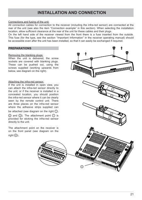
PREPARATIONS<br />
Removing the blanking plugs:<br />
When the unit is delivered, the screw<br />
sockets are covered with blanking plugs.<br />
These can be pushed out, using the<br />
screws supplied (working upwards from<br />
below, see diagram on the right).<br />
Attaching the infra-red sensor:<br />
If the unit is installed in open view, you<br />
can attach the infra-red sensor directly to<br />
the unit; or if the receiver is installed in a<br />
concealed location, you should position<br />
the infra-red sensor where it can be clearly<br />
seen by the remote control unit. There<br />
are three places on the infra-red sensor<br />
where the adhesive strips supplied can<br />
be attached (see diagram on the right ,<br />
and ). The attachment point is<br />
provided for sticking the infra-red sensor<br />
directly to the unit.<br />
INSTALLATION AND CONNECTION<br />
Connections and fusing of the unit:<br />
All connection cables for connection to the receiver (including the infra-red sensor) are connected at the<br />
rear of the unit (see also the item “Connection example” in this section). When selecting the installation<br />
location, allow suffi cient clearance at the rear of the unit for these cables and their plugs.<br />
On the left hand side of the receiver viewed from the front there is a fuse inserted from the outside.<br />
This fuse (for the type, see the section “Important Information” in the receiver operating manual) should<br />
be accessible even after the unit has been installed, so that it can easily be exchanged if required.<br />
The attachment point on the receiver is<br />
on the front panel (see diagram on the<br />
right ).<br />
<br />
<br />
<br />
<br />
<br />
21