BLOCKING READER: DESIGN AND IMPLEMENTATION OF A ...
BLOCKING READER: DESIGN AND IMPLEMENTATION OF A ...
BLOCKING READER: DESIGN AND IMPLEMENTATION OF A ...

You also want an ePaper? Increase the reach of your titles
YUMPU automatically turns print PDFs into web optimized ePapers that Google loves.
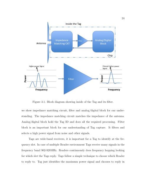
Figure 3.1. Block diagram showing inside of the Tag and its filter.<br />
we show impedance matching circuit, filter and analog/digital block for our under-<br />
standing. The impedance matching circuit matches the impedance of the antenna.<br />
Analog/digital block hold the Tag ID and does all the required processing. Filter<br />
block is an important block for our understanding of Tag capture. It filters and<br />
selects a high power signal from noise and other signals.<br />
Tags are wide-band receivers, it is important for a Tag to identify at the fre-<br />
quency slot. In case of multiple Reader environment Tags receive many signals in the<br />
frequency band 902-928MHz. Readers continuously does frequency hopping looking<br />
for which slot the Tags reply. Tags follow a simple technique to choose which Reader<br />
to reply to. Tag just identifies the maximum power signal and chooses to reply in<br />
24