OPERATOR'S MANUAL BIOPROtect II JR Vent to ... - Baker Company
OPERATOR'S MANUAL BIOPROtect II JR Vent to ... - Baker Company
OPERATOR'S MANUAL BIOPROtect II JR Vent to ... - Baker Company
You also want an ePaper? Increase the reach of your titles
YUMPU automatically turns print PDFs into web optimized ePapers that Google loves.
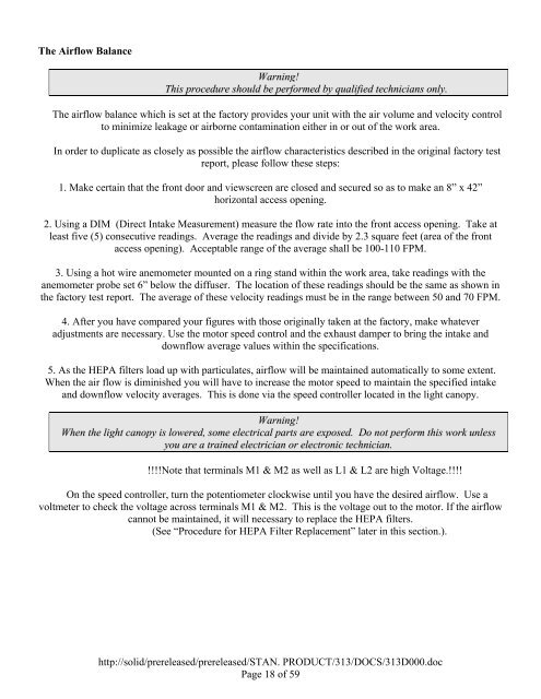
The Airflow Balance<br />
Warning!<br />
This procedure should be performed by qualified technicians only.<br />
The airflow balance which is set at the fac<strong>to</strong>ry provides your unit with the air volume and velocity control<br />
<strong>to</strong> minimize leakage or airborne contamination either in or out of the work area.<br />
In order <strong>to</strong> duplicate as closely as possible the airflow characteristics described in the original fac<strong>to</strong>ry test<br />
report, please follow these steps:<br />
1. Make certain that the front door and viewscreen are closed and secured so as <strong>to</strong> make an 8” x 42”<br />
horizontal access opening.<br />
2. Using a DIM (Direct Intake Measurement) measure the flow rate in<strong>to</strong> the front access opening. Take at<br />
least five (5) consecutive readings. Average the readings and divide by 2.3 square feet (area of the front<br />
access opening). Acceptable range of the average shall be 100-110 FPM.<br />
3. Using a hot wire anemometer mounted on a ring stand within the work area, take readings with the<br />
anemometer probe set 6” below the diffuser. The location of these readings should be the same as shown in<br />
the fac<strong>to</strong>ry test report. The average of these velocity readings must be in the range between 50 and 70 FPM.<br />
4. After you have compared your figures with those originally taken at the fac<strong>to</strong>ry, make whatever<br />
adjustments are necessary. Use the mo<strong>to</strong>r speed control and the exhaust damper <strong>to</strong> bring the intake and<br />
downflow average values within the specifications.<br />
5. As the HEPA filters load up with particulates, airflow will be maintained au<strong>to</strong>matically <strong>to</strong> some extent.<br />
When the air flow is diminished you will have <strong>to</strong> increase the mo<strong>to</strong>r speed <strong>to</strong> maintain the specified intake<br />
and downflow velocity averages. This is done via the speed controller located in the light canopy.<br />
Warning!<br />
When the light canopy is lowered, some electrical parts are exposed. Do not perform this work unless<br />
you are a trained electrician or electronic technician.<br />
!!!!Note that terminals M1 & M2 as well as L1 & L2 are high Voltage.!!!!<br />
On the speed controller, turn the potentiometer clockwise until you have the desired airflow. Use a<br />
voltmeter <strong>to</strong> check the voltage across terminals M1 & M2. This is the voltage out <strong>to</strong> the mo<strong>to</strong>r. If the airflow<br />
cannot be maintained, it will necessary <strong>to</strong> replace the HEPA filters.<br />
(See “Procedure for HEPA Filter Replacement” later in this section.).<br />
http://solid/prereleased/prereleased/STAN. PRODUCT/313/DOCS/313D000.doc<br />
Page 18 of 59


