OPERATOR'S MANUAL BIOPROtect II JR Vent to ... - Baker Company
OPERATOR'S MANUAL BIOPROtect II JR Vent to ... - Baker Company
OPERATOR'S MANUAL BIOPROtect II JR Vent to ... - Baker Company

Create successful ePaper yourself
Turn your PDF publications into a flip-book with our unique Google optimized e-Paper software.
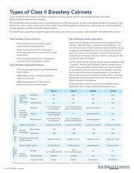
Specifications<br />
Dimensions:<br />
Outside: 66” W x 64.44” D x 106.41”H<br />
Usable work area: 51”W x 36.5”D x 75”H (under diffuser)<br />
Cart worksurface: 44”W x 34” D x (27”- 37”) H (height adjusted by opera<strong>to</strong>r).<br />
Weights<br />
Utilities:<br />
Mechanical<br />
Unit weight: The weight of the <strong>BIOPROtect</strong> <strong>II</strong> <strong>JR</strong> cabinet is approximately 1200 lbs.<br />
Cart weight: The weight of the <strong>BIOPROtect</strong> <strong>II</strong> <strong>JR</strong> cart is approximately 250 lbs.<br />
Maximum worksurface capacity: 500 Lbs. uniform load.<br />
Point loads not <strong>to</strong> exceed 125 Lbs. each<br />
Four (4) 3/8” NPT female connections provided for plumbing; all are pre-plumbed <strong>to</strong> the <strong>to</strong>p of the<br />
unit using 3/8” copper tubing. No service fixtures or valves are provided. User must supply fixtures <strong>to</strong><br />
mate with 3/8” NPT female connection on side walls (see general arrangement drawing for details).<br />
Electrical<br />
!!! This cabinet is powered from more than one power source. The cabinet is not electrically safe unless<br />
all power sources are disconnected. Proper Lockout/Tag out procedures should be used !!!<br />
All electrical wiring should comply with the National Electric Code and any applicable Local Electrical<br />
Codes at the site of installation.<br />
The standard <strong>BIOPROtect</strong> <strong>II</strong> Jr has three junction boxes located on the front of the <strong>to</strong>p deck. The<br />
following services need <strong>to</strong> be connected <strong>to</strong> the junction boxes.<br />
One 120Volt, 20Amp, 60 Hz, Single phase connection <strong>to</strong> power the blower. This circuit should be wired<br />
using 12 AWG wire and provided with a 20 Amp circuit breaker that will serve as a disconnect for this<br />
power supply.<br />
One 120 V, 15Amp, 60 Hz, Single phase connection for control power and power <strong>to</strong> the left side wall<br />
duplex. This circuit should be wired using 14 AWG wire and provided with a 15 Amp circuit breaker that<br />
will serve as a disconnect for this power supply.<br />
One 120 V, 15Amp, 60 Hz, Single phase connection for power <strong>to</strong> the right side wall duplex. This circuit<br />
should be wired using 14 AWG wire and provided with a 15 Amp circuit breaker that will serve as a<br />
disconnect for this power supply.<br />
The circuit breakers for these services are <strong>to</strong> be located in close proximity <strong>to</strong> the cabinet.<br />
Other connections may be required for optional equipment.<br />
http://solid/prereleased/prereleased/STAN. PRODUCT/313/DOCS/313D000.doc<br />
Page 4 of 59