ON THE EFFECTS OF CIRCULAR BOLT PATTERNS ON THE ...
ON THE EFFECTS OF CIRCULAR BOLT PATTERNS ON THE ...
ON THE EFFECTS OF CIRCULAR BOLT PATTERNS ON THE ...
Create successful ePaper yourself
Turn your PDF publications into a flip-book with our unique Google optimized e-Paper software.
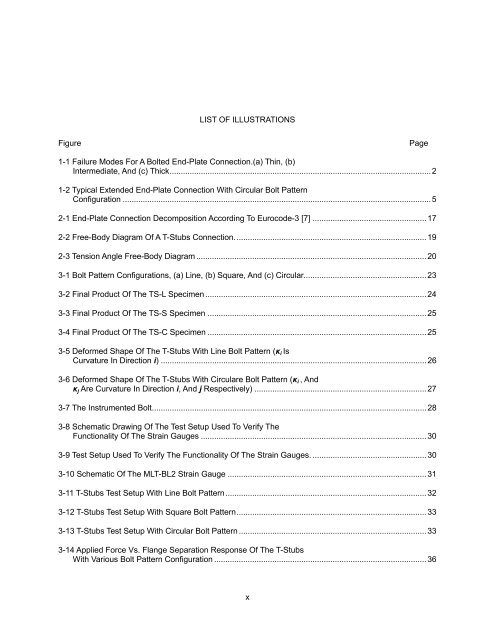
LIST <strong>OF</strong> ILLUSTRATI<strong>ON</strong>S<br />
Figure Page<br />
1-1 Failure Modes For A Bolted End-Plate Connection.(a) Thin, (b)<br />
Intermediate, And (c) Thick ..................................................................................................................... 2<br />
1-2 Typical Extended End-Plate Connection With Circular Bolt Pattern<br />
Configuration .......................................................................................................................................... 5<br />
2-1 End-Plate Connection Decomposition According To Eurocode-3 [7] ................................................... 17<br />
2-2 Free-Body Diagram Of A T-Stubs Connection. ..................................................................................... 19<br />
2-3 Tension Angle Free-Body Diagram ....................................................................................................... 20<br />
3-1 Bolt Pattern Configurations, (a) Line, (b) Square, And (c) Circular. ...................................................... 23<br />
3-2 Final Product Of The TS-L Specimen ................................................................................................... 24<br />
3-3 Final Product Of The TS-S Specimen .................................................................................................. 25<br />
3-4 Final Product Of The TS-C Specimen .................................................................................................. 25<br />
3-5 Deformed Shape Of The T-Stubs With Line Bolt Pattern (κi Is<br />
Curvature In Direction i) ....................................................................................................................... 26<br />
3-6 Deformed Shape Of The T-Stubs With Circulare Bolt Pattern (κi , And<br />
κj Are Curvature In Direction i, And j Respectively) ............................................................................. 27<br />
3-7 The Instrumented Bolt ........................................................................................................................... 28<br />
3-8 Schematic Drawing Of The Test Setup Used To Verify The<br />
Functionality Of The Strain Gauges ..................................................................................................... 30<br />
3-9 Test Setup Used To Verify The Functionality Of The Strain Gauges. ................................................... 30<br />
3-10 Schematic Of The MLT-BL2 Strain Gauge ......................................................................................... 31<br />
3-11 T-Stubs Test Setup With Line Bolt Pattern .......................................................................................... 32<br />
3-12 T-Stubs Test Setup With Square Bolt Pattern ..................................................................................... 33<br />
3-13 T-Stubs Test Setup With Circular Bolt Pattern .................................................................................... 33<br />
3-14 Applied Force Vs. Flange Separation Response Of The T-Stubs<br />
With Various Bolt Pattern Configuration ............................................................................................... 36<br />
x


