ON THE EFFECTS OF CIRCULAR BOLT PATTERNS ON THE ...
ON THE EFFECTS OF CIRCULAR BOLT PATTERNS ON THE ...
ON THE EFFECTS OF CIRCULAR BOLT PATTERNS ON THE ...
You also want an ePaper? Increase the reach of your titles
YUMPU automatically turns print PDFs into web optimized ePapers that Google loves.
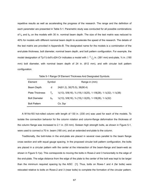
epetitive results as well as accelerating the progress of the research. The range and the definition of<br />
each parameter are presented in Table 5-1. Parametric study was conducted for all possible combinations<br />
of tp and bd on the models with 30 in. nominal beam depth. The size of the test matrix was reduced to<br />
40% for models with different nominal beam depth to accelerate the speed of the research. The details of<br />
the test matrix are provided in Appendix-B. The designated name for the models is a combination of the<br />
end-plate thickness, bolt diameter, nominal beam depth, and bolt pattern configuration. For example, the<br />
model designation of Tp1½-bd¾-d24-Cir indicates a model with 1 1 <br />
2<br />
in. (381 mm) end-plate, ¾ in. (190<br />
mm) bolt diameter, with nominal beam depth of 24 in. (612 mm), and with circular bolt pattern<br />
configuration.<br />
Table 5-1 Range Of Element Thickness And Designated Symbols.<br />
Element Symbol Range in (mm)<br />
Beam Depth d 24(61.2), 30(75.5), 36(90.4)<br />
Plate Thickness Tp ½(13), 5/8(16), ¾ (19),1.0(25), 1-1/8(28), 1-¼(32), 1-½(38)<br />
Bolt Diameter bd ½(13), 5/8(16), ¾ (19),1.0(25), 1-1/8(28), 1-¼(32)<br />
Bolt Pattern Cir, Sqr<br />
A W14x193 hot-rolled column with length of 130 in. (330 cm) was used for each of the models. To<br />
isolate the connection behavior for the column rotation and column-flange deformation the thickness of<br />
the column flange was increased to 2.1 in. (53 mm). Sixteen high strength bolts, as shown in Figure 5-1,<br />
were used to connect a 70 in. beam (180 cm), and an extended end-plate to the column.<br />
Traditionally, the bolt-holes in the end-plate are placed in several rows parallel to the beam flange<br />
cross section and with equal gauge spacing. In the proposed circular bolt pattern configuration, the bolts<br />
are placed in a circular pattern with the center at the intersection of the beam-flange and beam-web as<br />
shown in Figure 5-1(a). This corresponds to moving the bolts in Rows-2 and 3 horizontally to the edge of<br />
the end-plate. The edge distance from the edge of the plate to the center of the bolt was kept to be larger<br />
than the minimum required spacing by the AISC [1]. Thus, bolts on Rows-1 and 4 (far bolts) were<br />
relocated relative to bolts on Rows-2 and 3 (near bolts) to complete the formation of the circular pattern.<br />
67


