Collapsible Core Design & Assembly Guide - DME
Collapsible Core Design & Assembly Guide - DME
Collapsible Core Design & Assembly Guide - DME

You also want an ePaper? Increase the reach of your titles
YUMPU automatically turns print PDFs into web optimized ePapers that Google loves.
<strong>DME</strong><br />
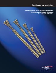
<strong>Collapsible</strong> <strong>Core</strong><br />
<strong>Design</strong> Check List and Mold Start-up Procedures<br />
Things to look for in mold design and in checking out molds prior to operation:<br />
1. Use guided ejector plates and support ring around center pin between ejector plate and ejector housing or back clamp plate (doughnut<br />
around pin).<br />
2. First break to occur at main parting line. Use springs to assure.<br />
3. Return pins to be located under, not through, stripper plate.<br />
4. Ejector travel to specification, stamp on edge of ejector plate.<br />
5. Secondary stripper actuation only after full ejector plate travel. Use properly set micro-switch or other means. Stripper-plate must return<br />
fully before ejector plate begins return (see Sequence Description).<br />
6. When top face of <strong>Collapsible</strong> <strong>Core</strong> segments shut off against cavity (for some parts with through holes), all cores must be ground to same<br />
length overall. Normal core tolerance of plus or minus .003 is inadequate. Whenever the above condition exists, an early ejector return<br />
system must be used. Clearance between end of core segments and cavity to be .0005/.001. Do not pre-load.<br />
7. Good venting is essential, preferably to outside of mold at parting line.<br />
8. Clearance between core and stripper bushing (.0010/.0015 total) on diameter at room temperature. No tapered mold seal-off below thread<br />
or configuration. Measure O.D. of core at stripper bushing when core is installed in mold with stripper plate removed.<br />
9. Verify for center pin protrusion and pin tip radius. Examine pins for evidence of any de-temper of pin tip due to overheating in grinding.<br />
10. Mounted core in ejector plate assembly to be free to turn if part design allows.<br />
11. Center pin and stripper bushing to be concentric. Water line baffle in center pin sometimes tends to throw pin off, or pin may be<br />
improperly mounted.<br />
12. Positive collapse sleeve to travel freely, both when starting up and when mold is at operating temperature. Grease lightly.<br />
13. Check finish on cores:<br />
– Surface finish and polish.<br />
– Undercuts and back-hooks in direction of collapse due to improper grinding.<br />
– Compliance with proper design procedures.<br />
14. Observe proper care in dry cycling:<br />
– Plate cocking or bounce.<br />
– Audible sounds or visible indications of friction, misalignment or scoring.<br />
– Sequence of motions (see Sequence Description).<br />
– Positive collapse action.<br />
15. Threads ground into <strong>Collapsible</strong> <strong>Core</strong> should not run out to a feather/knife edge.<br />
16. Refer to Sequence Description for desired Sequence of Automatic Mold Operation.<br />
www.dme.net<br />
7