Collapsible Core Design & Assembly Guide - DME
Collapsible Core Design & Assembly Guide - DME
Collapsible Core Design & Assembly Guide - DME

Create successful ePaper yourself
Turn your PDF publications into a flip-book with our unique Google optimized e-Paper software.
Mold desiGn check lisT<br />
<strong>DME</strong><br />
<strong>Collapsible</strong> <strong>Core</strong><br />
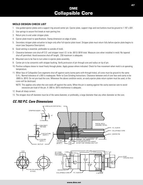
1. Use guided ejector plates and a support ring around center pin. Ejector plate, support rings and rest buttons must be ground to 1.187 ±.001.<br />
2. Use springs to assure first break at main parting line.<br />
3. Return pins to end under stripper plate.<br />
4. Ejector plate travel to specifications. Stamp dimension on edge of plate.<br />
5. Secondary stripper plate actuation to begin only after full ejector plate travel. Stripper plate must return fully before ejector plate begins to<br />
return (see Sequence Description).<br />
6. Good venting is essential, preferable to outside of mold.<br />
7. Clearance between core shut-off O.D. and stripper insert I.D. to be .0013/.0018 total. Measure core when installed in mold. No tapered<br />
shut-off permitted. Avoid excessive shut-off length; .250 maximum is adequate.<br />
8. Mounted core to be free to turn when in ejector plate assembly.<br />
9. Center pin to be concentric with stripper bushing. Verify protrusion of pin through core and radius on tip of pin.<br />
10. Positive collapse sleeve to travel freely through plates. Apply grease where indicated. Check for free movement when mold is at operating<br />
temperature.<br />
11. When face of <strong>Collapsible</strong> <strong>Core</strong> segments shut-off against cavity (some parts with through holes), all cores must be ground to the same<br />
O.A.L. Normal tolerance of ±.003 is inadequate. Refer to <strong>Core</strong> Grinding Instructions. Clearance between end of core face and cavity to be<br />
.0005 to .0010. Do not pre-load the core. Whenever the above condition exists, an early ejector plate return system must be used, or the<br />
cores will be destroyed.<br />
NOTE: This applies only when the core seals off against the cavity. When the pin is seating against the cavity exercise care to avoid<br />
excessive pre-load of the pin. A .000 to .0015 interference is adequate.<br />
12. Break all sharp corners.<br />
13. The stripper shut-off diameter must be of the same diameter, or preferably, a large diameter than any other diameter on the core.<br />
CC 702 P.C. <strong>Core</strong> Dimensions<br />
1.810<br />
MIN<br />
STRIPPER INSERT<br />
3°<br />
.060 FLAT<br />
0.165 COLLAPSE MIN<br />
AT FACE<br />
0.010<br />
0.010<br />
5°MIN DRAFT<br />
PER SIDE<br />
0.030 FLAT MIN<br />
(NOTE 7)<br />
R.020 MIN<br />
(NOTE 1)<br />
(CIRCULAR STEP DETAIL)<br />
15°<br />
.045 MIN<br />
.075 MAX<br />
(NOTE 1)<br />
60° C'SINK 0.390<br />
BOTH ENDS<br />
FOR GRINDING<br />
Ø4.225<br />
Ø2.777±.005 MIN<br />
STK<br />
CENTER PIN<br />
COLLAPSIBLE CORE<br />
2.250<br />
2.400<br />
0.787<br />
NOM<br />
R.06<br />
2.400<br />
www.dme.net<br />
0.030 MIN CLEARANCE REF<br />
0.030 MIN CLEARANCE<br />
0.250 MAX SHUT OFF HEIGHT<br />
DO NOT USE TAPERED SHUT OFF<br />
P.C. SLEEVE<br />
11.250 ±.004<br />
7.157 NOM<br />
Ø5.321<br />
NOM<br />
Ø5.686<br />
NOM<br />
PARTIAL MOLD<br />
ASSEMBLY DETAIL<br />
Ø4.444 ±.001<br />
Ø4.874 +.000<br />
-.010<br />
0.188 NOM<br />
1.625 ±.005<br />
(NOTE 4)<br />
0.374 ±.001<br />
Ø3.000<br />
±.001<br />
1.750 MIN<br />
+.000<br />
Ø3.410 -.010<br />
P.C. SLEEVE<br />
COLLAPSIBLE CORE<br />
CENTER PIN<br />
47<br />
Ø.937<br />
COOLING HOLE