Collapsible Core Design & Assembly Guide - DME
Collapsible Core Design & Assembly Guide - DME
Collapsible Core Design & Assembly Guide - DME

Create successful ePaper yourself
Turn your PDF publications into a flip-book with our unique Google optimized e-Paper software.
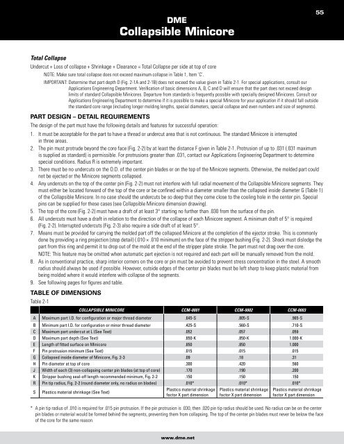
Total Collapse<br />
<strong>DME</strong><br />
<strong>Collapsible</strong> Minicore<br />
Undercut + Loss of collapse + Shrinkage + Clearance = Total Collapse per side at top of core<br />
NOTE: Make sure total collapse does not exceed maximum collapse in Table 1, Item ‘C’.<br />
IMPORTANT: Determine that part depth D (Fig. 2-1A and 2-1B) does not exceed the value given in Table 2-1. For special applications, consult our<br />
Applications Engineering Department. Verification of basic dimensions A, B, C and D will ensure that the part does not exceed design<br />
limits of standard <strong>Collapsible</strong> Minicores. Departure from standards is frequently possible with specially designed Minicores. Consult our<br />
Applications Engineering Department to determine if it is possible to make a special Minicore for your application if it should fall outside<br />
the standard core range (including longer molding lengths, special diameters, special collapse and even numbers and size of segments).<br />
parT desiGn – deTail requireMenTs<br />
The design of the part must have the following details and features for successful operation:<br />
1. It must be acceptable for the part to have a thread or undercut area that is not continuous. The standard Minicore is interrupted<br />
in three areas.<br />
2. The pin must protrude beyond the core face (Fig. 2-2) by at least the distance F given in Table 2-1. Protrusion of up to .031 (.031 maximum<br />
is supplied as standard) is permissible. For protrusions greater than .031, contact our Applications Engineering Department to determine<br />
special conditions. Radius R is extremely important.<br />
3. There must be no undercuts on the O.D. of the center pin blades or on the top of the Minicore segments. Otherwise, the molded part could<br />
not be ejected or the Minicore segments collapsed.<br />
4. Any undercuts on the top of the center pin (Fig. 2-2) must not interfere with full radial movement of the <strong>Collapsible</strong> Minicore segments. They<br />
must either be located forward of the top of the core or be confined within a diameter smaller than the collapsed inside diameter G (Table 1)<br />
of the <strong>Collapsible</strong> Minicore. In no case should the undercuts be so deep that they come close to the cooling hole in the center pin. Special<br />
pins can be supplied for these cases (see <strong>Collapsible</strong> Minicore dimension drawing).<br />
5. The top of the core (Fig. 2-2) must have a draft of at least 3° starting no further than .030 from the surface of the pin.<br />
6. All undercuts must have a draft in relation to the direction of the collapse of each Minicore segment. A minimum draft of 5° is required<br />
(Fig. 2-2). Interrupted undercuts (Fig. 2-3) also require a side draft of at least 5°.<br />
7. Means must be provided for carrying the molded part off the collapsed Minicore at the completion of the ejector stroke. This is commonly<br />
done by providing a ring projection (step detail) (.010 × .010 minimum) on the face of the stripper bushing (Fig. 2-2). Shock must dislodge the<br />
part from this ring and permit it to drop out of the mold at the end of the stripper plate stroke. The part must not drag over the core.<br />
NOTE: This feature may be omitted when automatic part ejection is not required and each part will be manually removed from the mold.<br />
8. As in conventional practice, sharp interior corners on the core or pin must be avoided to prevent stress concentration in the steel. A smooth<br />
radius should always be used if possible. However, outside edges of the center pin blades must be left sharp to keep plastic material from<br />
being molded where it would interfere with collapse of the segments.<br />
9. See following pages for figures and table.<br />
Table of diMensions<br />
Table 2-1<br />
COLLAPSIBLE MINICORE CCM-0001 CCM-0002 CCM-0003<br />
A Maximum part I.D. for configuration or major thread diameter .645-S .805-S .965-S<br />
B Minimum part I.D. for configuration or minor thread diameter .425-S .560-S .710-S<br />
C Maximum part undercut at L (See Text) .052 .057 .059<br />
D Maximum part depth (See Text) .850-K .850-K 1.000-K<br />
E Length of fitted surface on Minicore .850 .850 1.000<br />
F Pin protrusion minimum (See Text) .015 .015 .015<br />
G Collapsed inside diameter of Minicore, Fig. 2-3 .09 .18 .31<br />
H Pin diameter at top of core .300 .420 .560<br />
J Width of each (3) non-collapsing center pin blades (at top of core) .170 .190 .200<br />
K Stripper bushing seal-off length recommended minimum, Fig. 2-2 .150 .150 .150<br />
R Pin tip radius, Fig. 2-2 (round diameter only, no radius on blades) .010* .010* .010*<br />
S Plastics material shrinkage (See Text)<br />
Plastics material shrinkage<br />
factor X part dimension<br />
Plastics material shrinkage<br />
factor X part dimension<br />
Plastics material shrinkage<br />
factor X part dimension<br />
* A pin tip radius of .010 is required for .015 pin protrusion. If the pin protrusion is .030, then .020 pin tip radius should be used. No radius can be on the center<br />
pin blades or material would be formed behind the segments, preventing them from collapsing. The top of the center pin blades must never be below the face<br />
of the core for the same reason.<br />
www.dme.net<br />
55