Collapsible Core Design & Assembly Guide - DME
Collapsible Core Design & Assembly Guide - DME
Collapsible Core Design & Assembly Guide - DME

Create successful ePaper yourself
Turn your PDF publications into a flip-book with our unique Google optimized e-Paper software.
<strong>DME</strong><br />
<strong>Collapsible</strong> <strong>Core</strong><br />
<strong>Collapsible</strong> <strong>Core</strong>: Description of Components and Basic Operation<br />
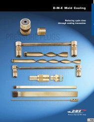
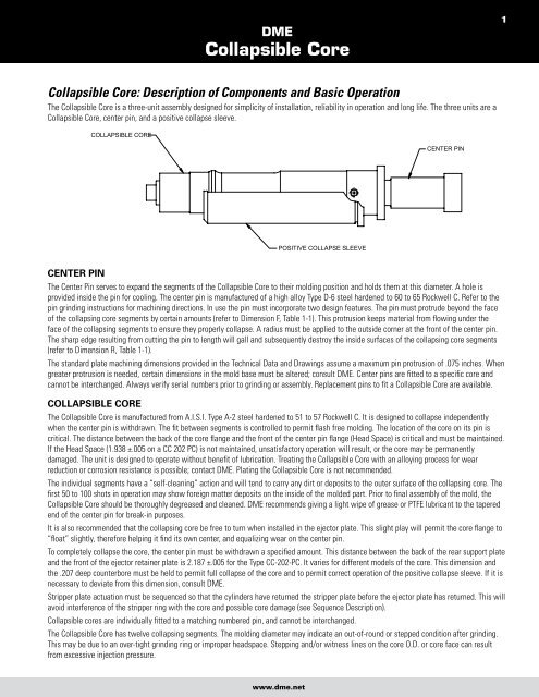
The <strong>Collapsible</strong> <strong>Core</strong> is a three-unit assembly designed for simplicity of installation, reliability in operation and long life. The three units are a<br />
<strong>Collapsible</strong> <strong>Core</strong>, center pin, and a positive collapse sleeve.<br />
COLLAPSIBLE CORE<br />
POSITIVE COLLAPSE SLEEVE<br />
www.dme.net<br />
CENTER PIN<br />
cenTer pin<br />
The Center Pin serves to expand the segments of the <strong>Collapsible</strong> <strong>Core</strong> to their molding position and holds them at this diameter. A hole is<br />
provided inside the pin for cooling. The center pin is manufactured of a high alloy Type D-6 steel hardened to 60 to 65 Rockwell C. Refer to the<br />
pin grinding instructions for machining directions. In use the pin must incorporate two design features. The pin must protrude beyond the face<br />
of the collapsing core segments by certain amounts (refer to Dimension F, Table 1-1). This protrusion keeps material from flowing under the<br />
face of the collapsing segments to ensure they properly collapse. A radius must be applied to the outside corner at the front of the center pin.<br />
The sharp edge resulting from cutting the pin to length will gall and subsequently destroy the inside surfaces of the collapsing core segments<br />
(refer to Dimension R, Table 1-1).<br />
The standard plate machining dimensions provided in the Technical Data and Drawings assume a maximum pin protrusion of .075 inches. When<br />
greater protrusion is needed, certain dimensions in the mold base must be altered; consult <strong>DME</strong>. Center pins are fitted to a specific core and<br />
cannot be interchanged. Always verify serial numbers prior to grinding or assembly. Replacement pins to fit a <strong>Collapsible</strong> <strong>Core</strong> are available.<br />
collapsible core<br />
The <strong>Collapsible</strong> <strong>Core</strong> is manufactured from A.I.S.I. Type A-2 steel hardened to 51 to 57 Rockwell C. It is designed to collapse independently<br />
when the center pin is withdrawn. The fit between segments is controlled to permit flash free molding. The location of the core on its pin is<br />
critical. The distance between the back of the core flange and the front of the center pin flange (Head Space) is critical and must be maintained.<br />
If the Head Space (1.938 ±.005 on a CC 202 PC) is not maintained, unsatisfactory operation will result, or the core may be permanently<br />
damaged. The unit is designed to operate without benefit of lubrication. Treating the <strong>Collapsible</strong> <strong>Core</strong> with an alloying process for wear<br />
reduction or corrosion resistance is possible; contact <strong>DME</strong>. Plating the <strong>Collapsible</strong> <strong>Core</strong> is not recommended.<br />
The individual segments have a “self-cleaning” action and will tend to carry any dirt or deposits to the outer surface of the collapsing core. The<br />
first 50 to 100 shots in operation may show foreign matter deposits on the inside of the molded part. Prior to final assembly of the mold, the<br />
<strong>Collapsible</strong> <strong>Core</strong> should be thoroughly degreased and cleaned. <strong>DME</strong> recommends giving a light wipe of grease or PTFE lubricant to the tapered<br />
end of the center pin for break-in purposes.<br />
It is also recommended that the collapsing core be free to turn when installed in the ejector plate. This slight play will permit the core flange to<br />
“float” slightly, therefore helping it find its own center, and equalizing wear on the center pin.<br />
To completely collapse the core, the center pin must be withdrawn a specified amount. This distance between the back of the rear support plate<br />
and the front of the ejector retainer plate is 2.187 ±.005 for the Type CC-202-PC. It varies for different models of the core. This dimension and<br />
the .207 deep counterbore must be held to permit full collapse of the core and to permit correct operation of the positive collapse sleeve. If it is<br />
necessary to deviate from this dimension, consult <strong>DME</strong>.<br />
Stripper plate actuation must be sequenced so that the cylinders have returned the stripper plate before the ejector plate has returned. This will<br />
avoid interference of the stripper ring with the core and possible core damage (see Sequence Description).<br />
<strong>Collapsible</strong> cores are individually fitted to a matching numbered pin, and cannot be interchanged.<br />
The <strong>Collapsible</strong> <strong>Core</strong> has twelve collapsing segments. The molding diameter may indicate an out-of-round or stepped condition after grinding.<br />
This may be due to an over-tight grinding ring or improper headspace. Stepping and/or witness lines on the core O.D. or core face can result<br />
from excessive injection pressure.<br />
1