Collapsible Core Design & Assembly Guide - DME
Collapsible Core Design & Assembly Guide - DME
Collapsible Core Design & Assembly Guide - DME

Create successful ePaper yourself
Turn your PDF publications into a flip-book with our unique Google optimized e-Paper software.
<strong>DME</strong><br />
<strong>Collapsible</strong> Minicore<br />
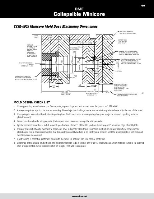
CCM-0003 Minicore Mold Base Machining Dimensions<br />
Mold desiGn check lisT<br />
1. Use support ring around center pin. Ejector plate, support rings and rest buttons must be ground to 1.187 ±.001.<br />
2. Always use guided ejection for ejector assembly. <strong>Guide</strong>d ejection bushings locate ejector retainer plate and core with the rest of the mold.<br />
3. Use springs to assure first break at main parting line. (Mold must open at main parting line prior to ejector assembly pushing stripper<br />
plate forward.)<br />
4. Return pins to end under stripper plate. (Return pins must never run through the stripper plate.)<br />
5. Ejector assembly must travel to full forward specification. Stamp “1.688 ±.005 ejection stroke required” on visible edge of mold plate.<br />
6. Stripper plate actuation by cylinders to begin only after full ejector plate travel. Cylinders must return stripper plate fully before ejector<br />
plate begins return. It is recommended that the ejector assembly be held in its full forward position until the stripper plate is fully returned<br />
(see Sequence Description).<br />
7. Good venting is essential, preferably to outside the mold. Do not vent part into core or center pin.<br />
8. Clearance between core shut-off O.D. and stripper insert I.D. to be a total of .0010/.0015. Measure core when installed in mold. No tapered<br />
shut-of is permitted. Avoid excessive shut-off length; .150/.250 is adequate.<br />
www.dme.net<br />
69