Collapsible Core Design & Assembly Guide - DME
Collapsible Core Design & Assembly Guide - DME
Collapsible Core Design & Assembly Guide - DME

Create successful ePaper yourself
Turn your PDF publications into a flip-book with our unique Google optimized e-Paper software.
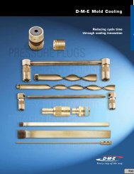
<strong>DME</strong><br />
<strong>Collapsible</strong> Minicore<br />
9. <strong>Core</strong> must be located with a key in the ejector retainer plate (key to have about .005 clearance with alignment flat on core). This prevents<br />
the core from rotating and aligns it closely with the center pin to orient center pin blades between the core segments.<br />
10. Center pin must be located with a key in the bottom of the housing (key to have about .005 clearance with alignment flat on pin).<br />
This prevents the pin from rotating and aligns it closely with the core to orient center pin blades with the core segments.<br />
NOTE: Alignment of both keys for core and pin is essential for proper fit, they must be parallel and on the same side.<br />
11. When core and pin are assembled in mold with 1.562 +.000/-.005 head space dimension, check to make sure that narrow blades on the<br />
center pin are never below the top of the collapsing segments.<br />
NOTE: A recess of the narrow blades below the top of the core segments will result in core damage.<br />
12. Center pin to be concentric with stripper bushing. Verify .015 pin protrusion beyond top of core and a minimum of .010 radius<br />
on tip of pin. Pin tip radius must always be slightly less than the pin protrusion to prevent plastic material from being formed behind<br />
the core segments. No radius permissible on center pin blades.<br />
13. Positive collapse sleeve to travel freely through “BX” support plate. Apply grease lightly to O.D. of positive collapse sleeve.<br />
Check for free movement when mold is at operating temperature.<br />
14. When the top of the core segments shut-off against cavity (example, some parts with through holes), all cores must be ground to the<br />
same length (O.A.L.). The normal tolerance of ±.003 is inadequate and may overload core. Refer to core grinding instructions.<br />
Clearance between top of core and cavity to be .0005 to .0010. Do not pre-load core. Whenever the above condition exists,<br />
an early ejector return system is mandatory.<br />
NOTE: This applies only when the top of the collapsing core segments shut off against the cavity. Also, exercise care to avoid pre-load on<br />
center pin. A .0000 to .0015 interference is adequate. Also, whenever above condition exists, the head space dimension in the mold<br />
must be held to exactly what was used to grind the length (O.A.L.) for each core with a tolerance of +.0000 to -.0010. All cores must<br />
be set up for grinding with exactly the same head space using a tolerance of +.0010 to -.0000. This must be done to prevent the top<br />
of the blades on the center pin from ever falling below the top of the collapsing segments on the core, which, if it occurred, would<br />
cause serious damage to the core.<br />
15. The stripper shut-off diameter must be the same or, preferably, a larger diameter than any other diameter on the core.<br />
www.dme.net<br />
67