Collapsible Core Design & Assembly Guide - DME
Collapsible Core Design & Assembly Guide - DME
Collapsible Core Design & Assembly Guide - DME

Create successful ePaper yourself
Turn your PDF publications into a flip-book with our unique Google optimized e-Paper software.
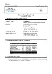
CC 150 P.C. <strong>Core</strong> Dimensions<br />
.037<br />
MIN<br />
.260<br />
3°<br />
.030 FLAT<br />
C'SINK<br />
BOTH ENDS<br />
FOR GRINDING<br />
5°<br />
.030 FLAT MIN<br />
(NOTE 7)<br />
R .008 MIN.<br />
(SEE NOTE 1)<br />
Ø0.850<br />
MIN STK<br />
0.239<br />
NOM<br />
.125<br />
0.580 ±.005<br />
CENTER PIN<br />
COLLAPSIBLE CORE<br />
<strong>DME</strong><br />
<strong>Collapsible</strong> <strong>Core</strong><br />
.015 MIN<br />
.075 MAX<br />
(NOTE 1)<br />
1.000<br />
CENTER SCREWS ON<br />
MIDDLE OF LARGE<br />
SEGMENT<br />
1.125 MAX<br />
.850<br />
1.000<br />
CIRCULAR STEP DETAIL<br />
R.03<br />
.150 MIN/.200 MAX SHUT-OFF HEIGHT.<br />
DO NOT USE TAPERED SHUT-OFF.<br />
www.dme.net<br />
.030 MIN CLEARANCE<br />
.030 MIN. CLEARANCE<br />
Ø1.600 NOM<br />
6.615 ±.003<br />
4.270 NOM<br />
P.C. SLEEVE<br />
Ø1.750 NOM<br />
SET-UP GRINDING<br />
REFER TO GRINDING<br />
INFORMATION<br />
.685<br />
0.188<br />
NOM<br />
0.250 ±.001<br />
Ø1.305 +.000<br />
-.001<br />
15°<br />
P.C. SLEEVE<br />
Ø1.610 +.000<br />
-.010<br />
COLLAPSIBLE CORE<br />
CENTER PIN<br />
1.625 ±.005<br />
(NOTE 4)<br />
Ø0.780 ±.001<br />
1.625 ±.005<br />
0.010<br />
STRIPPER INSERT<br />
0.010<br />
0.6<br />
MIN<br />
Ø1.000 +.000<br />
-.010<br />
1.625 ±.005<br />
(NOTE 4)<br />
Ø.312<br />
COOLING HOLE<br />
USE SCREWS TO<br />
ALIGN CORE ON PIN INDICATE HERE FOR<br />
GRINDING .003 MAX T.I.R.<br />
NOTES:<br />
1. Center pin to project .015 minimum/.075 maximum above front face of <strong>Collapsible</strong> <strong>Core</strong> with .008 R minimum at corners. See suggested partial mold<br />
assembly view.<br />
2. Both ends of center pin to be cut off after grinding contour on <strong>Collapsible</strong> <strong>Core</strong> before assembly in mold.<br />
3. Minimum suggested I.D. of thread or undercut is 0.700-S to give minimum steel support between depth of undercut and center pin.<br />
4. The 1.625 ±.005 dimension must be held in mold assembly and core grinding.<br />
5. Consult Grinding Instructions.<br />
6. A 1 ⁄32 radius is essential on the inside corners of the stripper insert, especially where shut-off contacts <strong>Collapsible</strong> <strong>Core</strong>.<br />
7. Thread must never be run out of face of core, leaving a knife-edge of material. For complete instructions, refer to <strong>Design</strong> Procedures.<br />
8. Do not use center pin as a pilot into “A” half of mold.<br />
13