Collapsible Core Design & Assembly Guide - DME
Collapsible Core Design & Assembly Guide - DME
Collapsible Core Design & Assembly Guide - DME
You also want an ePaper? Increase the reach of your titles
YUMPU automatically turns print PDFs into web optimized ePapers that Google loves.
50<br />
<strong>DME</strong><br />
<strong>Collapsible</strong> <strong>Core</strong><br />
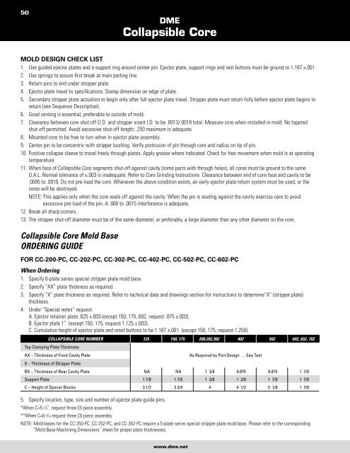
Mold desiGn check lisT<br />
1. Use guided ejector plates and a support ring around center pin. Ejector plate, support rings and rest buttons must be ground to 1.187 ±.001.<br />
2. Use springs to assure first break at main parting line.<br />
3. Return pins to end under stripper plate.<br />
4. Ejector plate travel to specifications. Stamp dimension on edge of plate.<br />
5. Secondary stripper plate actuation to begin only after full ejector plate travel. Stripper plate must return fully before ejector plate begins to<br />
return (see Sequence Description).<br />
6. Good venting is essential, preferable to outside of mold.<br />
7. Clearance between core shut-off O.D. and stripper insert I.D. to be .0013/.0018 total. Measure core when installed in mold. No tapered<br />
shut-off permitted. Avoid excessive shut-off length; .250 maximum is adequate.<br />
8. Mounted core to be free to turn when in ejector plate assembly.<br />
9. Center pin to be concentric with stripper bushing. Verify protrusion of pin through core and radius on tip of pin.<br />
10. Positive collapse sleeve to travel freely through plates. Apply grease where indicated. Check for free movement when mold is at operating<br />
temperature.<br />
11. When face of <strong>Collapsible</strong> <strong>Core</strong> segments shut-off against cavity (some parts with through holes), all cores must be ground to the same<br />
O.A.L. Normal tolerance of ±.003 is inadequate. Refer to <strong>Core</strong> Grinding Instructions. Clearance between end of core face and cavity to be<br />
.0005 to .0010. Do not pre-load the core. Whenever the above condition exists, an early ejector plate return system must be used, or the<br />
cores will be destroyed.<br />
NOTE: This applies only when the core seals off against the cavity. When the pin is seating against the cavity exercise care to avoid<br />
excessive pre-load of the pin. A .000 to .0015 interference is adequate.<br />
12. Break all sharp corners.<br />
13. The stripper shut-off diameter must be of the same diameter, or preferably, a large diameter than any other diameter on the core.<br />
<strong>Collapsible</strong> <strong>Core</strong> Mold Base<br />
ORDERING GUIDE<br />
for cc-200-pc, cc-202-pc, cc-302-pc, cc-402-pc, cc-502-pc, cc-602-pc<br />
When Ordering<br />
1. Specify 6-plate series special stripper plate mold base.<br />
2. Specify “AX” plate thickness as required.<br />
3. Specify “X” plate thickness as required. Refer to technical data and drawings section for instructions to determine“X” (stripper plate)<br />
thickness.<br />
4. Under “Special notes” request:<br />
A. Ejector retainer plate .625 ±.003 (except 150, 175, 602, request .875 ±.003).<br />
B. Ejector plate 1”. (except 150, 175, request 1.125 ±.003).<br />
C. Cumulative height of ejector plate and reset buttons to be 1.187 ±.001. (except 150, 175, request 1.250).<br />
COLLAPSIBLE CORE NUMBER<br />
Top Clamping Plate Thickness<br />
125 150, 175 200,202,302 402 502 602, 652, 702<br />
AX – Thickness of Front Cavity Plate<br />
X – Thickness of Stripper Plate<br />
As Required by Part <strong>Design</strong> … See Text<br />
BX – Thickness of Rear Cavity Plate NA NA 1 3/8 0.875 0.875 1 7/8<br />
Support Plate 1 7/8 1 7/8 1 3/8 1 3/8 1 7/8 1 7/8<br />
C – Height of Spacer Blocks 3 1/2 3 3/4 4 4 1/2 5 1/8 1 7/8<br />
5. Specify location, type, size and number of ejector plate guide pins.<br />
*When C=5-1 ⁄8”, request three (3) piece assembly.<br />
**When C=6-3 ⁄16 request three (3) piece assembly.<br />
NOTE: Mold bases for the CC-250-PC, CC-252-PC, and CC-352-PC require a 5-plate series special stripper plate mold base. Please refer to the corresponding<br />
“Mold Base Machining Dimensions” sheet for proper plate thicknesses.<br />
www.dme.net


