Collapsible Core Design & Assembly Guide - DME
Collapsible Core Design & Assembly Guide - DME
Collapsible Core Design & Assembly Guide - DME

You also want an ePaper? Increase the reach of your titles
YUMPU automatically turns print PDFs into web optimized ePapers that Google loves.
<strong>DME</strong><br />
<strong>Collapsible</strong> <strong>Core</strong><br />
<strong>Design</strong> Procedure – Plastic Parts to be Molded on <strong>Collapsible</strong> <strong>Core</strong>s<br />
General consideraTions<br />
All commonly used thermoplastic molding resins, including filled materials, have been successfully molded on <strong>Collapsible</strong> <strong>Core</strong>s. Vinyl resins<br />
have been tried. Certain injectable thermosets have also been tried. However, cores must be treated with a corrosion resistant process, such as<br />
a dense nodular chrome (contact <strong>DME</strong>). (However, in general, we cannot recommend thermosets due to extreme ease of flashing and the very<br />
abrasive nature of many of these materials.) For high temperature applications over 650°F, contact <strong>DME</strong>.<br />
Good plastic product design practices should be observed to avoid such conditions as distortion, sink marks, etc. These problems and their<br />
solutions are identical to those found in conventional molding. Adequate venting is important. Gases must always be vented to the outside<br />
of the part, away from the core and center pin.<br />
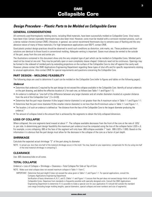
The illustrations contained in this document show only the very simplest type of part which can be molded on <strong>Collapsible</strong> <strong>Core</strong>s. Molded parts<br />
need not be closed at one end. They may be partially open or even completely sleeve shaped. Undercuts need not be continuous. Openings may<br />
be formed in the sidewall of molded parts by extending projections on the surface of the <strong>Collapsible</strong> <strong>Core</strong> to shut off against the cavity wall.<br />
However, please contact the <strong>DME</strong> Applications Engineering Department regarding these types of shut-offs and for specific requirements relating<br />
to unusual applications. Also contact <strong>DME</strong> for special requirements and questions concerning the <strong>Collapsible</strong> <strong>Core</strong>.<br />
parT desiGn – MoldinG feasibiliTy<br />
The following steps are used to determine if a part can be molded on the <strong>Collapsible</strong> <strong>Core</strong> (refer to figures and tables on the following pages):<br />
Undercut<br />
• Determine that undercuts C required by the part design do not exceed the collapse available in the <strong>Collapsible</strong> <strong>Core</strong>. Identify all actual undercuts<br />
on the part drawing, and define the effective location of J for each one, as follows (see Table 1-1 and Figure 1-1).<br />
• An undercut is defined as “one-half of the difference between any larger diameter and all smaller diameters located at a greater distance<br />
from the end of the <strong>Collapsible</strong> <strong>Core</strong>” [.5 x (A-B)].<br />
• Determine that the part major diameter A (the largest interior diameter) is not greater than the A maximum value in Table 1-1 and Figure 1-1.<br />
• Determine that the part minor diameter B (the smaller interior diameter) is not less than the B minimum value in Table 1-1 and Figure 1-1.<br />
• The location J of such an undercut is defined as “the distance from the face of the <strong>Collapsible</strong> <strong>Core</strong> to the largest diameter producing the<br />
undercut.”<br />
• The amount of collapse listed is the amount that is achieved by the segments to obtain the fully collapsed dimension.<br />
loss of collapse<br />
When collapsed, the core segments bend inward at about 1°. The collapse available decreases from the front of the core at the rate of .020/<br />
in. per side. In determining part design feasibility the maximum part undercut must be computed using the loss of the collapse factor (.020 x J).<br />
For example, a core collapsing .080 at the face of the segment will only have .060 collapse available 1” back: .080-(.020 x 1.000). Based on the<br />
information it is obvious that the part design must allow for the decrease in the collapse of the core as a factor of part depth.<br />
shrinkaGe<br />
Calculate the expected actual shrinkage “S” of the part along its diameter.<br />
NOTE: In actual use, less than one-half of the material shrinkage occurs in the mold. You may, based on your experience, compensate for this by using one-half<br />
of the total material shrinkage in computing S.<br />
clearance<br />
Use .005 clearance/side on all cores.<br />
ToTal collapse<br />
Undercut + Loss of Collapse + Shrinkage + Clearance = Total Collapse Per Side at Top of <strong>Core</strong>.<br />
NOTE: Make sure total collapse does not exceed maximum collapse in Table 1-1 Item C.<br />
IMPORTANT: Determine that part depth D does not exceed the value given in Table 1-1 and Figure 1-1. For special applications, consult the<br />
Company Applications Engineering Department.<br />
Verification of basic dimensions A, B, C, and D, (Table 1-1 and Figure 1-1) assure that the part does not exceed design limits of standard<br />
<strong>Collapsible</strong> <strong>Core</strong>s. Departure from standards is frequently possible with specially designed units. Consult the <strong>DME</strong> Applications<br />
Engineering Department to determine if it is possible to make a special core for your application if it should fall outside the standard<br />
core range (including longer molding lengths, special diameters, special collapse and even numbers and size of segments).<br />
www.dme.net<br />
3