Collapsible Core Design & Assembly Guide - DME
Collapsible Core Design & Assembly Guide - DME
Collapsible Core Design & Assembly Guide - DME
Create successful ePaper yourself
Turn your PDF publications into a flip-book with our unique Google optimized e-Paper software.
<strong>DME</strong><br />
<strong>Collapsible</strong> Minicore<br />
cenTer pin (WiTh Three non-collapsinG narroW blades)<br />
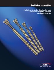
The center pin serves to expand the segments of the Minicore to their molding position and holds them at this diameter. Blades at the molding<br />
end of the center pin fit closely between the collapsing segments of the Minicore. When the core is lifted off the center pin blades, room is<br />
provided for the Minicore segments to collapse. A hole is provided in the center pin for cooling. The center pin is manufactured of a high alloy<br />
type D-6 tool steel hardened to 60 to 65 Rockwell “C”, except for the head area, which is a soft stainless steel, and is brazed to the center pin<br />
shaft. Refer to the pin grinding instructions for machining directions. In use, the pin must incorporate two design features. The pin must protrude<br />
beyond the top of the Minicore segments by certain amounts; refer to Dimension F in the Table of Dimensions. A radius must be applied to the<br />
.300, .420, or .560 diameters of the center pin above the top of the core. This protrusion must keep material from flowing behind the segments<br />
that would prevent their collapse. The sharp edge resulting from cutting the pin to length will gall and subsequently destroy the inside surfaces<br />
The standard mold base machining dimensions provided in the <strong>Collapsible</strong> Minicore drawings assume a maximum pin protrusion of .031. When<br />
greater protrusion is needed, a special center pin and certain dimensions in the mold base must be altered. Please consult with our Applications<br />
Engineering Department. Center pins are fitted to a specific core and cannot be interchanged. Always assemble core and pin with alignment<br />
flats parallel and on the same side. Always verify serial numbers and flat alignment of core and pin prior to assembly or grinding. Replacement<br />
center pins to fit <strong>Collapsible</strong> Minicores are available on special order.<br />
posiTive collapse sleeve<br />
The positive collapse sleeve (PC sleeve) is designed to function when any of the <strong>Collapsible</strong> Minicore segments fail to collapse independently upon<br />
withdrawal of the center pin. In normal operation, the PC sleeve is not functioning. It is essential to have such a unit for maximum safety and reliability<br />
in automatic and semi-automatic operation. Under no circumstances should a mold be placed into operation without the use of the PC Sleeve.<br />
The PC sleeve is uncomplicated in operation. An angular surface on the inside of the front edge of the PC sleeve will engage a matching angular<br />
surface on the outside of the <strong>Collapsible</strong> Minicore when the un-collapsed Minicore is moved forward in the PC sleeve. This interference action<br />
is achieved by restricting the travel of the PC sleeve to an amount less than the forward travel of the <strong>Collapsible</strong> Minicore.<br />
It is essential that no variation be permitted from the dimension given between the rear of the back support and the front of the ejector retainer<br />
plate. The .207 +.003/-.002 deep counterbore for the head of the PC sleeve must also be maintained. Do not deviate from these dimensions<br />
without prior approval of our Applications Engineering Department. Any variation from these dimensions will adversely affect the operation of<br />
the PC sleeve and may cause destruction of the Minicore.<br />
PC sleeves are interchangeable between different serial numbers of the same catalog number (size) core.<br />
Tapered Work arbor for GrindinG (WiTh no blades or head)<br />
The tapered work arbor is used for grinding threads or undercuts on collapsing Minicore segments only.<br />
claMpinG rinG for GrindinG (WiTh seT screWs)<br />
The clamping ring for grinding is used to hold Minicore segments in place during all grinding operations of the Minicore.<br />
desired sequence of operaTion of collapsible core for auToMaTic Mold operaTion<br />
As indicated on each Mold Base Machining Dimension drawing for the <strong>Collapsible</strong> Minicore, the cross section depicts a typical collapsible core<br />
mold design. The <strong>Collapsible</strong> Minicore is mounted in the ejector retainer plate; the center pin is mounted in a bottom clamp plate. An extended<br />
stripper plate has been incorporated for proper ejection and cylinders are shown installed for the last stage of the required two-stage ejection.<br />
Also, vital to the design is the usage of guided ejection.<br />
The molding sequence can easily be followed by starting with the opening of the press: the press opens and the mold parts at the main parting<br />
line. When sufficient mold open is achieved, the ejector plate assembly is moved forward by mechanical or hydraulic knockouts of the press. The<br />
ejector plate assembly with the <strong>Collapsible</strong> Minicore is moving forward the necessary stroke required to move the core off of the center pin and<br />
collapse the core (this is the first stage of ejection).<br />
If the segments of the core fail to collapse for any reason during this stage, the positive collapse sleeve will come into play and ensure the start<br />
of the collapse. In addition, the stripper plate and ejector plate assembly move together because of the return pins located directly under the<br />
stripper plate. This simultaneous movement continues until the ejector plate assembly is full forward. At this point, a limit switch is actuated.<br />
This in turn actuates the cylinders to take over and to continue to move the stripper plate with the stripper insert, moving the part away from the<br />
collapsed core (second stage).<br />
When automatic part stripping is required, means must be provided for carrying the molded part off of the collapsed Minicore at the completion<br />
of the ejector stroke. This is commonly done by providing a ring projection (.010 × .010 min.) on the face of the stripper insert. Shock dislodges<br />
the part from this ring and permits it to drop out of the mold at the end of the stripper stroke. The part must not drag over the core. When<br />
removing the part manually, the stripper ring and the cylinders are not required.<br />
www.dme.net<br />
53


