MIC Green Book
MIC Green Book
MIC Green Book

You also want an ePaper? Increase the reach of your titles
YUMPU automatically turns print PDFs into web optimized ePapers that Google loves.
C H A P T E R O N E<br />
THEOR Y<br />
6<br />
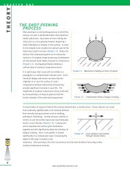
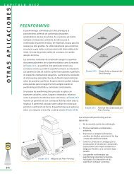
SUMMATION OF APPLIED AND RESIDUAL STRESS<br />
When a component is shot peened and subjected to<br />
an applied load, the surface of the component<br />
experiences the net stress from the applied load and<br />
shot peening residual stress. Figure 1-6 depicts a<br />
bar with a three-point load that creates a bending<br />
stress at the surface.<br />
The diagonal dashed line is the tensile stress created<br />
from the bending load. The curved dashed line is the<br />
(residual) compressive stress from shot peening. The<br />
solid line is the summation of the two showing a<br />
significant reduction of tensile stress at the surface.<br />
Shot peening is highly advantageous for the<br />
following two conditions:<br />
• Stress risers • High strength<br />
materials<br />
Stress risers may consist of radii, notches, cross holes, grooves, keyways, etc. Shot peening induces a high<br />
magnitude, localized compressive stress to offset the stress concentration factor created from these<br />
geometric changes.<br />
Shot peening is ideal for high strength materials. Compressive stress is directly correlated to a material’s<br />
tensile strength. The higher the tensile strength, the more compressive stress that can be induced. Higher<br />
strength materials have a more rigid crystal structure. This crystal lattice can withstand greater degrees of<br />
strain and consequently can store more residual stress.<br />
Application Case Study<br />
NASA LANGLEY CRACK GROWTH STUDY<br />
Figure 1-6 Resultant Stress in a Shot Peened<br />
Beam with an External Load Applied<br />
Engineers at NASA performed a study on crack growth rates of 2024-T3 aluminum with and without shot<br />
peening. The samples were tested with an initial crack of 0.050" (1.27 mm) and then cycle tested to failure. It<br />
should be noted that the United States Air Force damage tolerance rogue flaw is 0.050" (1.27 mm).<br />
It was found that crack growth was significantly delayed when shot peening was included. As the following<br />
results demonstrate, at a 15 ksi (104 MPa) net stress condition the remaining life increased by 237%. At a 20<br />
ksi (138 MPa) net stress condition the remaining life increased by 81%.<br />
This test reflects conditions that are harsher than real world conditions. Real world conditions would generally<br />
not have initial flaws and should respond with better fatigue life improvements at these stress levels.<br />
NON-SHOT PEENED TEST RESULTS<br />
Net Number Average<br />
Stress Of Tests Life Cycles<br />
15 ksi 2 75,017<br />
20 3 26,029<br />
SHOT PEENED TEST RESULTS<br />
Net Number Average Percent<br />
Stress Of Tests Life Cycles Increase<br />
15 ksi 2 253,142 237%<br />
20 3 47,177 81%<br />
Note on sample preparation: A notch was placed in the surface via the EDM process. The samples were loaded<br />
in fatigue until the crack grew to ~ 0.050" (1.27 mm). If samples were shot peened, they were peened after the<br />
initial crack of 0.050" (1.27 mm) was generated. This was the starting point for the above results. [Ref 1.1]<br />
www.metalimprovement.com