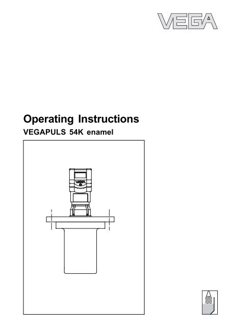
Operating Instructions - VEGAPULS 54K enamel
Operating Instructions - VEGAPULS 54K enamel
Operating Instructions - VEGAPULS 54K enamel

You also want an ePaper? Increase the reach of your titles
YUMPU automatically turns print PDFs into web optimized ePapers that Google loves.
<strong>Operating</strong> <strong>Instructions</strong><br />
<strong>VEGAPULS</strong> <strong>54K</strong> <strong>enamel</strong>
Contents<br />
Sicherheitshinweise ..................................................................... 3<br />
Safety information ........................................................................ 3<br />
Note Ex area ................................................................................ 3<br />
1 Product description .................................................................. 4<br />
1.1 Function................................................................................. 4<br />
1.2 Application features ............................................................. 6<br />
1.3 Adjustment ............................................................................ 6<br />
1.4 Antennas ............................................................................... 8<br />
2 Mounting and installation ....................................................... 9<br />
2.1 General installation instructions .......................................... 9<br />
2.2 Measurement of liquids ..................................................... 10<br />
2.3 False echoes ...................................................................... 11<br />
2.4 Common installation mistakes........................................... 13<br />
3 Electrical connection .............................................................. 15<br />
3.1 Connection and connection cable .................................... 15<br />
3.2 Connecting the sensor ...................................................... 16<br />
3.3 Connecting the external indicating instrument<br />
VEGADIS 50 ....................................................................... 19<br />
3.4 Configuration of measuring systems ............................... 20<br />
4 Set-up ........................................................................................ 28<br />
4.1 Adjustment media .............................................................. 28<br />
4.2 Adjustment with PC............................................................ 28<br />
4.3 Adjustment with adjustment module MINICOM............... 30<br />
4.4 Adjustment with HART® handheld ................................... 36<br />
5 Diagnostics ............................................................................... 38<br />
5.1 Simulation ............................................................................ 38<br />
5.2 Error codes ........................................................................ 38<br />
Contents<br />
2 <strong>VEGAPULS</strong> <strong>54K</strong> <strong>enamel</strong><br />
24 101-EN-041227
24 101-EN-041227<br />
Sicherheitshinweise<br />
6 Technical data .......................................................................... 39<br />
6.1 Technical data ..................................................................... 39<br />
6.2 Approvals ........................................................................... 43<br />
6.3 Dimensions ......................................................................... 44<br />
Supplement ..................................................................................... 46<br />
Safety Manual ................................................................................. 46<br />
1 General ............................................................................... 46<br />
1.1 Validity ................................................................................. 46<br />
1.2 Area of application ............................................................... 46<br />
1.3 Relevant standards ............................................................. 46<br />
1.4 Determination of safety-related characteristics .................. 47<br />
2 Planning .............................................................................. 48<br />
2.1 Low demand mode ............................................................... 48<br />
2.2 High demand or continuous mode ....................................... 48<br />
2.3 General ................................................................................ 48<br />
3 Set-up ................................................................................. 49<br />
3.1 Mounting and installation ..................................................... 49<br />
3.2 Adjustment instructions and parameter settings ................ 49<br />
3.3 Configuration of the processing unit ................................... 49<br />
4 Reaction during operation and in case of failure ............. 50<br />
5 Recurring function test ....................................................... 50<br />
6 Safety-related characteristics ........................................... 51<br />
SIL declaration of conformity .................................................... 52<br />
CE declaration of conformity..................................................... 53<br />
Safety information<br />
Please read this manual carefully, and also take<br />
note of country-specific installation standards<br />
(e.g. the VDE regulations in Germany) as well<br />
as all prevailing safety regulations and accident<br />
prevention rules.<br />
For safety and warranty reasons, any internal<br />
work on the instruments, apart from that involved<br />
in normal installation and electrical connection,<br />
must be carried out only by VEGA<br />
personnel.<br />
Note Ex area<br />
Please note the attached safety instructions<br />
containing important information on installation<br />
and operation in Ex areas.<br />
These safety instructions are part of the operating<br />
instructions manual and come with the Ex<br />
approved instruments.<br />
<strong>VEGAPULS</strong> <strong>54K</strong> <strong>enamel</strong> 3
1 Product description<br />
<strong>VEGAPULS</strong> series 50 sensors are a newly<br />
developed generation of extremely compact,<br />
small radar sensors.<br />
Due to their small housing dimensions and<br />
process fittings, the compact sensors are an<br />
unobstrusive, and most of all, very costeffective<br />
solution for your level measurement<br />
applications. With their integrated display<br />
and many of the features of the <strong>VEGAPULS</strong><br />
81 series, they bring the advantages of radar<br />
level measurement to applications where<br />
previously, due to high costs, the advantages<br />
of non-contact measurement had to be<br />
forgone.<br />
The <strong>VEGAPULS</strong> 54 radar sensor is perfectly<br />
suitable for two-wire technology, however, it is<br />
also available in four-wire technology where<br />
the output signal and power supply are carried<br />
on in two separate circuits. The supply<br />
voltage and the output signal are transmitted<br />
via one two-wire cable. The instruments produce<br />
an analogue 4 … 20 mA output signal<br />
as output, i.e. measuring signal.<br />
In the <strong>enamel</strong>led version, the sensors have<br />
exceptional chemical resistance, and represent<br />
the ideal level sensor technology for<br />
corrosive processes.<br />
Radio detecting and ranging: Radar.<br />
<strong>VEGAPULS</strong> radar sensors are used for noncontact,<br />
continuous distance measurement.<br />
The measured distance corresponds to a<br />
filling height and is outputted as level.<br />
1.1 Function<br />
Measuring principle:<br />
Product description<br />
emission – reflection – reception<br />
Extremely small 5.8 GHz radar signals are<br />
emitted from the antenna of the radar sensor<br />
as short pulses. The radar pulses reflected<br />
by the sensor environment and the product<br />
are received by the antenna as radar echoes.<br />
The running period of the radar pulses<br />
from emission to reception is proportional to<br />
the distance and hence to the level.<br />
emission - reflection - reception<br />
Meas.<br />
distance<br />
The radar pulses are emitted by the antenna<br />
system as pulse packets with a pulse duration<br />
of 1 ns and pulse intervals of 278 ns; this<br />
corresponds to a pulse package frequency<br />
of 3.6 MHz. In the pulse intervals, the antenna<br />
system operates as a receiver. Signal running<br />
periods of less than one billionth of a<br />
second must be processed and the echo<br />
image evaluated in a fraction of a second.<br />
4 <strong>VEGAPULS</strong> <strong>54K</strong> <strong>enamel</strong><br />
24 101-EN-041227
24 101-EN-041227<br />
Product description<br />
Puls<br />
1 ns<br />
Pulse sequence<br />
Time transformation<br />
Pulse<br />
break<br />
278 ns<br />
<strong>VEGAPULS</strong> can achieve this through a special<br />
time transformation procedure which<br />
spreads out the more than 3.6 million echo<br />
images per second in a slow-motion picture,<br />
then freezes and processes them.<br />
t t<br />
Hence, it is possible for the <strong>VEGAPULS</strong> 50<br />
radar sensors to process the slow-motion<br />
pictures of the sensor environment precisely<br />
and in detail in cycles of 0.5 to 1 second<br />
without using time-consuming frequency<br />
analysis (e.g. FMCW, required by other radar<br />
techniques).<br />
Nearly all products can be measured<br />
Radar signals display physical properties<br />
similar to those of visible light. According to<br />
the quantum theory, they propagate through<br />
empty space. Hence, they are not dependent<br />
on a conductive medium (air), and they<br />
spread out like light at the speed of light.<br />
Radar signals react to two basic electrical<br />
properties:<br />
- the electrical conductivity of a substance<br />
- the dielectric constant of a substance.<br />
All products which are electrically conductive<br />
reflect radar signals very well. Even slightly<br />
conductive products provide a sufficiently<br />
strong reflection for a reliable measurement.<br />
All products with a dielectric constant ε r<br />
greater than 2.0 reflect radar pulses sufficiently<br />
(note: air has a dielectric constant ε r of<br />
1).<br />
Reflected radar power dependent on the dielectric<br />
constant of the measured product<br />
<strong>VEGAPULS</strong> <strong>54K</strong> <strong>enamel</strong> 5<br />
%<br />
50<br />
40<br />
30<br />
20<br />
10<br />
5<br />
0<br />
0<br />
5 %<br />
2<br />
25 %<br />
40 %<br />
4 6 8 12 14 16 18<br />
10<br />
20<br />
Signal reflectivity grows stronger with increasing<br />
conductivity or increasing dielectric<br />
constant of the product. Hence, nearly all<br />
substances can be measured.<br />
As process fitting, standard flanges of DN<br />
150, DN 200, ANSI 6“ or ANSI 8“ are used.<br />
Due to high quality <strong>enamel</strong> coating, the sensors<br />
withstand even extreme chemical and<br />
physical conditions. The sensors deliver<br />
stable, reproducible analogue or digital level<br />
signals with reliability and precision, and<br />
have a long useful life.<br />
ε r
Continuous and accurate<br />
Unaffected by temperature, pressure and<br />
atmosphere content, <strong>VEGAPULS</strong> radar sensors<br />
measure quickly and accurately the<br />
levels of widely varying products.<br />
%<br />
0,03<br />
0,02<br />
0,01<br />
0<br />
0<br />
100 500 1000 1300 ˚C<br />
Temperature influence: Temperature error absolutely<br />
zero (e.g. at 500°C 0.018 %)<br />
%<br />
10<br />
5<br />
0,29 %<br />
0<br />
10<br />
0<br />
0,018 %<br />
1,44 %<br />
20 30 40 60<br />
50<br />
0,023 %<br />
2,8 %<br />
3,89 %<br />
70 80 90 110 120 130 140<br />
100<br />
bar<br />
Pressure influence: Error with pressure increase very<br />
low (e.g. at 50 bar 1.44 %)<br />
<strong>VEGAPULS</strong> 50 sensors allow radar level<br />
measurement in plants where they were it<br />
was hitherto unthinkable because of high<br />
costs.<br />
1.2 Application features<br />
Applications<br />
level measurement of any liquid, limited use<br />
in solids<br />
measurement also in vacuum<br />
all slightly conductive materials and all<br />
substances with a dielectric constant > 2.0<br />
can be measured<br />
measuring range 0 … 20 m<br />
Two-wire technology<br />
power supply and output signal on one<br />
two-wire cable (Loop powered)<br />
4 … 20 mA output signal<br />
Rugged and abrasionproof<br />
non-contact<br />
high-resistance materials<br />
Product description<br />
Exact and reliable<br />
meas. resolution 1 mm<br />
unaffected by noise, vapours, dusts, gas<br />
compositions and inert gas stratification<br />
unaffected by varying density and temperature<br />
of the medium<br />
measurement in pressures of -1 … 16 bar<br />
and product temperatures of<br />
-40°C … 200°C<br />
Communicative<br />
integrated measured value display<br />
optional display module separate from<br />
sensor<br />
connection to all BUS systems: Interbus S,<br />
Modbus, Siemens 3964R, Profibus DP,<br />
Profibus FMS, ASCII<br />
adjustment from the PLC level with the PC<br />
adjustment with HART ® handheld<br />
adjustment with detachable adjustment<br />
module, pluggable in the sensor or in the<br />
external display<br />
Approvals<br />
CENELEC, ATEX, PTB, FM, CSA, ABS,<br />
LRS, GL, LR, FCC<br />
1.3 Adjustment<br />
Every measurement set-up is unique. For<br />
that reason, every radar sensor needs some<br />
basic information on the application and the<br />
environment, e.g. which level means "empty“<br />
and which level "full“. Beside this "empty and<br />
full adjustment“, many other settings and<br />
adjustments are possible with <strong>VEGAPULS</strong><br />
radar sensors.<br />
The adjustment and parameter setting of<br />
radar sensors is carried out with<br />
- the PC<br />
- the detachable adjustment module MINI-<br />
COM<br />
- the HART ® handheld<br />
6 <strong>VEGAPULS</strong> <strong>54K</strong> <strong>enamel</strong><br />
24 101-EN-041227
24 101-EN-041227<br />
Product description<br />
Adjustment with the PC<br />
The set-up and adjustment of the radar sensors<br />
is generally done on the PC with the<br />
adjustment software PACTware TM . The program<br />
leads quickly through the adjustment<br />
and parameter setting by means of pictures,<br />
graphics and process visualisations.<br />
Adjustment with the PC on the analogue 4 … 20 mA<br />
signal and supply cable or directly on the sensor<br />
(four-wire sensor)<br />
The PC can be connected at any measuring<br />
site in the system or directly to the signal<br />
cable. It is connected by means of the twowire<br />
PC interface converter VEGACONNECT 3<br />
to the sensor or the signal cable. The adjustment<br />
and parameter data can be saved with<br />
the adjustment software on the PC and can<br />
be protected by passwords. On request, the<br />
adjustments can be quickly transferred to<br />
other sensors.<br />
Adjustment with the PC on the 4 … 20 mA signal and<br />
supply cable to the PLC or directly on the sensor<br />
(figure: a two-wire sensor)<br />
2<br />
2<br />
2<br />
2<br />
PLC<br />
4 ...20 mA<br />
Adjustment with the adjustment module<br />
MINICOM<br />
With the small (3.2 cm x 6.7 cm) 6-key adjustment<br />
module with display, the adjustment<br />
can be carried out in clear text dialogue. The<br />
adjustment module can be plugged into the<br />
radar sensor or into the optional, external<br />
indicating instrument.<br />
Detachable adjustment module MINICOM<br />
<strong>VEGAPULS</strong> <strong>54K</strong> <strong>enamel</strong> 7<br />
Tank 1<br />
m (d)<br />
12.345<br />
- + ESC<br />
OK<br />
4<br />
2<br />
Tank 1<br />
m (d)<br />
12.345<br />
Tank 1<br />
m (d)<br />
12.345<br />
4 ... 20 mA<br />
- + ESC<br />
Adjustment with detachable adjustment module. The<br />
adjustment module can be plugged into the radar<br />
sensor or into the external indicating instrument<br />
VEGADIS 50.<br />
OK<br />
- + ESC<br />
Unauthorised sensor adjustments can be<br />
prevented by removing the adjustment module.<br />
OK
Adjustment with the HART ® handheld<br />
Series 50 sensors with 4 … 20 mA output<br />
signal can also be adjusted with the HART ®<br />
handheld. A special DDD (Data Device Description)<br />
is not necessary - the sensors can<br />
be adjusted with the HART ® standard menus<br />
of the handheld.<br />
HART ® handheld<br />
HART Communicator<br />
To make adjustments, simply connect the<br />
HART ® handheld to the 4 … 20 mA output<br />
signal cable or insert the two communication<br />
cables of the HART ® handheld into the adjustment<br />
jacks on the sensor.<br />
2<br />
2<br />
4 ...20 mA<br />
HART ® handheld on the 4 … 20 mA signal cable<br />
1.4 Antennas<br />
The antenna is the eye of the radar sensor.<br />
The shape of the antenna, however, doesn’t<br />
give a casual observer the slightest clue on<br />
how carefully the antenna geometry must be<br />
adapted to the physical properties of electromagnetic<br />
waves. The geometrical form determines<br />
focal properties and sensitivity - the<br />
same way it determines the sensitivity of a<br />
unidirectional microphone.<br />
Horn antennas<br />
Product description<br />
The horn antenna is the classical<br />
radar antenna in level<br />
measurement. The antenna<br />
focuses the radar signals very<br />
well. Fabricated of 1.4571<br />
(stainless steel) with <strong>enamel</strong><br />
coating or Hastelloy C22, the<br />
antenna is physicaly resistant,<br />
and is well suited for pressures<br />
up to 16 bar at product<br />
temperatures up to 200°C.<br />
8 <strong>VEGAPULS</strong> <strong>54K</strong> <strong>enamel</strong><br />
24 101-EN-041227
24 101-EN-041227<br />
Mounting and installation<br />
2 Mounting and installation<br />
2.1 General installation instructions<br />
Measuring range<br />
The reference plane for the measuring range<br />
of the sensor is the <strong>enamel</strong>led sensor seal<br />
shoulder, against which the <strong>enamel</strong>led vessel<br />
seal is placed. The measuring range is<br />
0 … 20 m. For measurements in surge or<br />
bypass tubes (pipe antenna) the max. measuring<br />
distance decreases by approx. 0.5 m.<br />
Keep in mind that in measuring environments<br />
where the medium can reach the sensor<br />
flange, buildup may form on the antenna and<br />
later cause measurement errors.<br />
max. filling<br />
Reference plane<br />
full empty<br />
max. meas. distance 20 m<br />
Measuring range (operating range) and max. measuring<br />
distance<br />
Note: Use of the sensors for applications with solids<br />
is limited.<br />
Measuring range<br />
False echoes<br />
Flat obstructions and struts cause strong<br />
false echoes. They reflect the radar signal<br />
with high energy density.<br />
Interfering surfaces with rounded profiles<br />
scatter the radar signals into the surrounding<br />
space more diffusely and thus generate false<br />
echoes with a lower energy density. Hence,<br />
those reflections are less critical than those<br />
from a flat surface.<br />
Profiles with flat interfering surfaces cause large<br />
false signals<br />
If flat obstructions in the range of the radar<br />
signals cannot be avoided, we recommend<br />
diverting the interfering signals with a deflector.<br />
The deflector prevents the interfering<br />
signals from being directly received by the<br />
radar sensor. The signals are then so lowenergy<br />
and diffuse that they can be filtered<br />
out by the sensor.<br />
Round profiles diffuse radar signals<br />
Cover flat interfering surfaces with deflectors<br />
<strong>VEGAPULS</strong> <strong>54K</strong> <strong>enamel</strong> 9
Emission cone and false echoes<br />
The radar signals are focused by the antenna<br />
system. The signals leave the antenna<br />
in a conical path similar to the beam pattern<br />
of a spotlight. This emission cone depends<br />
on the antenna used.<br />
Any object in this beam cone will reflect the<br />
radar signals. Within the first few meters of<br />
the beam cone, tubes, struts or other installations<br />
can interfere with the measurement. At a<br />
distance of 6 m, the false echo of a strut has<br />
an amplitude nine times greater than at a<br />
distance of 18 m.<br />
At greater distances, the energy of the radar<br />
signal distributes itself over a larger area,<br />
thus causing weaker echoes from obstructing<br />
surfaces. The interfering signals are<br />
therefore less critical than those at close<br />
range.<br />
If possible, orient the sensor axis perpendicularly<br />
to the product surface and avoid<br />
vessel installations (e.g. pipes and struts)<br />
within the 100% emission cone.<br />
If possible, provide a "clear view“ to the<br />
product inside the emission cone and avoid<br />
vessel installations in the first third of the<br />
emission cone.<br />
Optimum measuring conditions exist when<br />
the emission cone reaches the measured<br />
product perpendicularly and when the emission<br />
cone is free from obstructions.<br />
2.2 Measurement of liquids<br />
Horn antenna on DIN socket piece<br />
Radar sensors are usually mounted on short<br />
DIN socket pieces. The lower side of the<br />
instrument flange is the reference plane for<br />
the measuring range. The antenna must<br />
always protrude out of the flange pipe.<br />
Mounting on DIN socket piece<br />
Mounting on longer DIN socket pieces<br />
> 10 mm<br />
Mounting on round vessel tops<br />
Mounting and installation<br />
Reference plane<br />
If the DIN socket piece is longer, please<br />
make sure that the horn antenna protrudes at<br />
least 10 mm out of the socket.<br />
> 10 mm<br />
When mounting on dished or rounded vessel<br />
tops, the antenna must also protrude at least<br />
10 mm (longer side of socket).<br />
10 <strong>VEGAPULS</strong> <strong>54K</strong> <strong>enamel</strong><br />
24 101-EN-041227
24 101-EN-041227<br />
Mounting and installation<br />
On dished vessel tops, please do not mount<br />
the instrument in the centre or close to the<br />
vessel wall, but approx.½ vessel radius from<br />
the centre or from the vessel wall.<br />
Dished tank tops can act as paraboloidal<br />
reflectors. If the radar sensor is placed in the<br />
focal point of the parabolic tank top, the radar<br />
sensor receives amplified false echoes. The<br />
radar sensor should be mounted outside the<br />
focal point. Parabolically amplified echoes are<br />
thereby avoided.<br />
Reference plane<br />
1 /2 vessel<br />
radius<br />
Mounting on round vessel tops<br />
Horn antenna directly on the vessel top<br />
If the stability of the vessel will allow it (sensor<br />
weight), flat mounting directly on the vessel<br />
top is a good and cost-effective solution. The<br />
top side of the vessel is the reference plane.<br />
Mounting directly on flat vessel top<br />
Reference plane<br />
2.3 False echoes<br />
The radar sensor must be installed at a location<br />
where no installations or inflowing material<br />
cross the radar pulses. The following examples<br />
and instructions show the most frequent<br />
measuring problems and how to avoid them.<br />
Vessel protrusions<br />
Vessel forms with flat protrusions can make<br />
measurement very difficult due to their strong<br />
false echoes. Baffles mounted above these<br />
flat protrusions scatter the false echoes and<br />
guarantee a reliable measurement.<br />
Vessel protrusions (ledge)<br />
Intake pipes, i.e. for the mixing of materials -<br />
with a flat surface directed towards the sensor<br />
- should be covered with an angled baffle<br />
that scatters false echoes.<br />
Vessel protrusions (intake pipe)<br />
Correct Incorrect<br />
Correct Incorrect<br />
<strong>VEGAPULS</strong> <strong>54K</strong> <strong>enamel</strong> 11
Vessel installations<br />
Vessel installations, such as e.g. ladders,<br />
often cause false echoes. Make sure when<br />
planning your measuring location that the<br />
radar signals have free access to the measured<br />
product.<br />
Vessel installations<br />
Struts<br />
Correct Incorrect<br />
Ladder<br />
Ladder<br />
Struts, like other vessel installations, can<br />
cause strong false echoes that are superimposed<br />
on the useful echoes. Small baffles<br />
effectively prevent a direct reception of false<br />
echoes. These false echoes are scattered<br />
and diffused in the surrounding space and<br />
are then filtered out as "echo noise“ by the<br />
measuring electronics.<br />
Struts<br />
Correct Incorrect<br />
Shields<br />
Inflowing material<br />
Do not mount the instrument in or above the<br />
filling stream. Ensure that you detect the<br />
product surface and not the inflowing material.<br />
Inflowing material<br />
Buildup<br />
Buildup<br />
Mounting and installation<br />
Correct Incorrect<br />
If the sensor is mounted too close to the<br />
vessel wall, product buildup and other deposits<br />
on the vessel wall cause false echoes.<br />
Position the sensor at a sufficient distance<br />
from the vessel wall. Please also note chapter<br />
"4.1 General installation instructions“.<br />
Correct Incorrect<br />
12 <strong>VEGAPULS</strong> <strong>54K</strong> <strong>enamel</strong><br />
24 101-EN-041227
24 101-EN-041227<br />
Mounting and installation<br />
Strong product movements<br />
Strong turbulence in the vessel, e.g. caused<br />
by powerful stirrers or strong chemical reactions,<br />
can seriously interfere with the measurement.<br />
A surge or bypass tube (see<br />
illustration) of sufficient size always enables<br />
reliable and problem-free measurement even<br />
if strong turbulence occurs in the vessel,<br />
provided there is no product buildup in the<br />
tube.<br />
Correct Incorrect<br />
> 500 mm<br />
Strong product movements<br />
100 %<br />
75 %<br />
Products tending to slight buildup can be<br />
detected by using a measuring tube with<br />
150 mm nominal width or more. In a measuring<br />
tube of this size, buildup does not cause<br />
any problems.<br />
0 %<br />
2.4 Common installation mistakes<br />
Socket piece too long<br />
If the sensor is mounted in a socket extension<br />
that is too long, strong false echoes are<br />
generated which interfere with the measurement.<br />
Make sure that the horn antenna protrudes<br />
at least 10 mm out of the socket piece.<br />
Correct Incorrect<br />
<strong>VEGAPULS</strong> <strong>54K</strong> <strong>enamel</strong> 13<br />
> 10 mm<br />
Correct and incorrect socket length<br />
Parabolic effects on dished or arched<br />
vessel tops<br />
Round or parabolic tank tops act on the radar<br />
signals like a parabolic mirror. If the radar<br />
sensor is placed at the focal point of such a<br />
parabolic tank top, the sensor receives amplified<br />
false echoes. The optimum mounting<br />
location is generally in the range of half the<br />
vessel radius from the centre.<br />
< 10 mm<br />
1 /2<br />
radius<br />
Correct<br />
Mounting on a vessel with parabolic tank top<br />
Incorrect<br />
Incorrect
Wrong orientation to the product<br />
Weak measuring signals are generated if the<br />
sensor is not directly pointed at the product<br />
surface. Orient the sensor axis perpendicularly<br />
to the product surface to achieve optimum<br />
measuring results.<br />
Correct Incorrect<br />
Ladder<br />
Direct sensor vertically to the product surface<br />
Sensor too close to the vessel wall<br />
If the radar sensor is mounted too close to<br />
the vessel wall, strong false echoes can be<br />
caused. Buildup, rivets, screws or weld joints<br />
superimpose their echoes onto the product<br />
i.e. useful echo. Please ensure a sufficient<br />
distance from the sensor to the vessel wall.<br />
Sensor too close to the vessel wall<br />
Ladder<br />
If there are good reflection conditions (liquid<br />
medium, no vessel installations), we recommend<br />
locating the sensor where there is no<br />
vessel wall within the inner emission cone. For<br />
products in less favourable reflection environments,<br />
it is a good idea to also keep the<br />
outer emission cone free of interfering installations.<br />
Note chapter "4.1 General installation<br />
instructions“.<br />
Foam generation<br />
Thick, dense and creamy foam on the product<br />
can cause incorrect measurements. Take<br />
measures to avoid foam, measure in a bypass<br />
tube or use another measuring technology,<br />
e.g. capacitive meas. probes or<br />
hydrostatic pressure transmitters.<br />
Foam generation<br />
Mounting and installation<br />
14 <strong>VEGAPULS</strong> <strong>54K</strong> <strong>enamel</strong><br />
24 101-EN-041227
24 101-EN-041227<br />
Electrical connection<br />
3 Electrical connection<br />
3.1 Connection and connection<br />
cable<br />
Safety information<br />
As a rule, do all connecting work in the complete<br />
absence of line voltage. Always switch<br />
off the power supply before you carry out<br />
connecting work on the radar sensors. Protect<br />
yourself and the instruments, especially<br />
when using sensors which do not operate<br />
with low voltage.<br />
Qualified personnel<br />
Instruments which are not operated with<br />
protective low voltage or DC voltage must<br />
only be connected by qualified personnel.<br />
Connection and screening<br />
A standard two or four-wire cable (sensors<br />
with separate supply) with max. 2.5 mm 2 wire<br />
cross-section can be used for connection.<br />
Quite often, the "electromagnetic pollution"<br />
caused by electronic actuators, energy cables<br />
and transmitting stations is so considerable<br />
that the sensor cable should be<br />
screened.<br />
We recommend the use of screened cable.<br />
Screening is also a good preventative measure<br />
against future sources of interference.<br />
Ground the cable screen preferably on the<br />
sensor.<br />
It is a good idea to ground the cable screen<br />
on both ends. However, you must make sure<br />
that no ground equalisation currents flow<br />
through the cable screening. Ground equalisation<br />
currents can be avoided by potential<br />
equalisation systems. If ground equalisation<br />
cables are not available, grounding on both<br />
ends can be realised by connecting (e.g. in<br />
the switching cabinet) one end via a capacitor<br />
1) to the ground potential. Use a very lowresistance<br />
ground connection (foundation,<br />
plate or mains earth).<br />
Note!<br />
In Ex applications, grounding on both ends is<br />
not allowed due to potential transfer.<br />
Ex protection<br />
If an instrument is used in hazardous areas,<br />
the respective regulations, conformity certificates<br />
and type approvals for systems in Ex<br />
areas must be noted (e.g. DIN 0165).<br />
Intrinsically safe circuits must not be connected<br />
with more than one active instrument<br />
(i.e. an instrument delivering electrical energy)<br />
must not be connected. Please note<br />
the special installation regulations (DIN 0165).<br />
Connection cable<br />
Make sure that the connection cables are<br />
specified for the expected conditions in your<br />
systems. The cable must have an outer diameter<br />
between 5 and 9 mm (1/2 to 1/3 inch), or<br />
with Ex d housing, 3.1 … 8.7 mm (0.12 to<br />
0.34 inch). Otherwise, the seal effect of the<br />
cable entry would not be ensured.<br />
Cables for intrinsically safe circuits must be<br />
marked blue and may not be used for other<br />
circuits.<br />
Earth conductor terminal<br />
On <strong>VEGAPULS</strong> 54 sensors, the earth conductor<br />
terminal is galvanically connected to<br />
the flange.<br />
1) max. 10 nF, e.g. voltage resistance 1500 V,<br />
ceramic.<br />
<strong>VEGAPULS</strong> <strong>54K</strong> <strong>enamel</strong> 15
3.2 Connecting the sensor<br />
After mounting the sensor at the measurement<br />
location according to the instructions in<br />
chapter "4 Mounting and installation“, loosen<br />
the closing screw on top of the sensor. The<br />
sensor lid with the optional indication display<br />
can then be opened. Unscrew the sleeve nut<br />
and slip it over the connection cable (after<br />
removing about 10 cm of cable mantle). The<br />
sleeve nut of the cable entry has a self-locking<br />
ratchet that prevents it from opening on<br />
its own.<br />
Version with plastic housing<br />
Power supply<br />
4 … 20 mA (passive) 1)<br />
+ -<br />
1 2 C 3 4 5 6 7 8<br />
1 2 C 5 6 7 8<br />
+ -<br />
4...20 mA<br />
Tank 1<br />
m (d)<br />
12.345<br />
Communication<br />
To the indicating instrument in the<br />
sensor lid or to the external indicating<br />
instrument VEGADIS 50<br />
- + ESC<br />
Display<br />
Two-wire technology in<br />
plastic housing<br />
(loop powered)<br />
1) 4 … 20 mA passive means that the sensor<br />
consumes a level-dependent current of<br />
4 … 20 mA (consumer).<br />
OK<br />
Terminals<br />
(max. 2.5 mm 2<br />
wire cross-section)<br />
Sockets for connection of<br />
the HART ® handheld or<br />
the VEGACONNECT<br />
Pluggable<br />
adjustment<br />
module<br />
MINICOM<br />
Tank 1<br />
m (d)<br />
12.345<br />
- + ESC<br />
Electrical connection<br />
Now insert the cable through the cable entry<br />
into the sensor. Screw the sleeve nut back<br />
onto the cable entry and clamp the stripped<br />
wires of the cable into the proper terminal<br />
positions.<br />
The terminals hold the wire without a screw.<br />
Press the white opening levers with a small<br />
screwdriver and insert the copper core of the<br />
connection cable into the terminal opening.<br />
Check the hold of the individual wires in the<br />
terminals by lightly pulling on them.<br />
Power supply<br />
16 <strong>VEGAPULS</strong> <strong>54K</strong> <strong>enamel</strong><br />
+ -<br />
+ -<br />
1 2 C 3 4 5 6 7 8<br />
1 2 C 3 4 5 6 7 8<br />
(+) (-)<br />
L1 N<br />
4 … 20 mA (active) 2)<br />
Commu-<br />
+ -<br />
nication<br />
4...20 mA Display<br />
Four-wire technology in<br />
plastic housing<br />
(separate supply)<br />
OK<br />
Opening<br />
tabs<br />
2) 4 … 20 mA active means that the sensor provides<br />
a level-dependent current of 4 … 20 mA (current<br />
source).<br />
24 101-EN-041227
24 101-EN-041227<br />
Electrical connection<br />
Version with aluminium housing<br />
4 … 20 mA passive<br />
+ -<br />
1)<br />
Two-wire technology<br />
(loop powered)<br />
To the indicating instrument in the<br />
sensor lid or to the external indicating<br />
instrument VEGADIS 50<br />
1 2 C 3 4 5 6 7 8<br />
1 2 C 3 4 5 6 7 8<br />
(+) (-)<br />
L1 N<br />
Commu- +-<br />
nication 4...20mA Display<br />
-<br />
+<br />
ESC ESC<br />
OK OK<br />
M20 x 1.5<br />
(diameter of the<br />
connection cable<br />
5…9 mm)<br />
1) 4 … 20 mA passive means that the sensor<br />
consumes a level-dependent current of 4 … 20 mA<br />
(consumer).<br />
Sockets for connection<br />
of<br />
VEGACONNECT<br />
(communication<br />
sockets)<br />
Four-wire technology<br />
4 … 20 mA active<br />
+ -<br />
Voltage supply<br />
+ -<br />
2)<br />
To the indicating<br />
instrument in the sensor<br />
lid or to the external<br />
indicating instrument<br />
M20 x 1.5<br />
(diameter of<br />
the connection<br />
cable<br />
VEGADIS 50<br />
6…9 mm) M20 x 1.5<br />
1 2 C 3 4 5 6 7 8<br />
1 2 C 3 4 5 6 7 8<br />
<strong>VEGAPULS</strong> <strong>54K</strong> <strong>enamel</strong> 17<br />
(+) (-)<br />
L1 N<br />
Commu- +-<br />
nication 4...20mA Display<br />
-<br />
2) 4 … 20 mA active means that the sensor provides<br />
a level-dependent current of 4 … 20 mA (current<br />
source).<br />
+<br />
ESC ESC<br />
OK OK
compartment<br />
Two-wire EEx d terminal compartment<br />
(opening in Ex atmosphere not allowed)<br />
-+ Power supply<br />
ser.no ********<br />
R<br />
ATEX<br />
FM<br />
APPROVED<br />
R<br />
Supply: 20...36V DC/4...20mA HART<br />
- +<br />
IS<br />
GND 2 1<br />
Exd terminal compartment<br />
1 /2 “ NPT EEx d<br />
diameter of the<br />
connection cable<br />
3.1…8.7 mm<br />
(0.12…0.34 inch)<br />
Electrical connection<br />
Version with aluminium housing and pressure-tight encapsulated terminal<br />
R<br />
supply<br />
4...20mA<br />
1 2 20...72V DC<br />
3 4 5<br />
R<br />
HART<br />
IS<br />
+ - 20...250V AC<br />
GND - +<br />
ser.no ********<br />
Locking of the cover<br />
Two-wire adjustment module terminal<br />
compartment<br />
(opening in Ex area permitted)<br />
1 /2 “ NPT EEx d<br />
diameter of the<br />
connection cable<br />
to the Exd<br />
terminal compartment<br />
3.1…8.7 mm<br />
(0.12…0.34 inch)<br />
1 2 C 5 6 7 8<br />
1 2 C 5 6 7 8<br />
18 <strong>VEGAPULS</strong> <strong>54K</strong> <strong>enamel</strong><br />
(+) (-)<br />
L1 N<br />
Exd safe connection to the<br />
Exd terminal compartment<br />
Communication<br />
Display<br />
Four-wire EEx d terminal compartment Four-wire adjustment module terminal<br />
compartment<br />
(opening in Ex area permitted)<br />
Exd safe connection to the<br />
Exd terminal compartment<br />
+ - -+<br />
Power supply<br />
4 ... 20 mA<br />
Locking of the cover<br />
Exd terminal<br />
compartment<br />
1 /2 “ NPT EEx d<br />
diameter of the<br />
connection cable<br />
to the Exd terminal<br />
compartment<br />
3.1…8.7 mm<br />
(0.12…0.34 inch)<br />
1 /2 “ NPT EEx d<br />
diameter of the<br />
connection cable<br />
to the Exd<br />
terminal compartment<br />
3.1…8.7 mm<br />
(0.12…0.34 inch)<br />
-<br />
+<br />
-<br />
ESC ESC<br />
OK OK<br />
1 2 C 5 6 7 8<br />
1 2 C 5 6 7 8<br />
(+) (-)<br />
L1 N<br />
Communication<br />
Display<br />
+<br />
ESC ESC<br />
OK OK<br />
24 101-EN-041227
24 101-EN-041227<br />
Electrical connection<br />
3.3 Connecting the external indicating<br />
instrument VEGADIS 50<br />
Loosen the four screws of the housing lid on<br />
VEGADIS 50.<br />
The connection procedure can be facilitated<br />
by fixing the housing cover during connection<br />
work with one or two screws on the right<br />
of the housing.<br />
Four-wire sensor in aluminium housing<br />
(separate supply)<br />
OUTPUT<br />
(to the sensor)<br />
SENSOR 1 2 3 4 5 6 7 8 DISPLAY<br />
Power supply<br />
+<br />
-<br />
1 2 C 3 4 5 6 7 8<br />
1 2 C 3 4 5 6 7 8<br />
(+) (-)<br />
L1 N<br />
Commu- +-<br />
nication 4...20mA Display<br />
-<br />
+<br />
DISPLAY<br />
(in the lid of the indicating<br />
instrument)<br />
ESC ESC<br />
OK OK<br />
4 … 20 mA<br />
active<br />
VEGADIS 50<br />
Adjustment<br />
module<br />
- + ESC<br />
<strong>VEGAPULS</strong> <strong>54K</strong> <strong>enamel</strong> 19<br />
Tank 1<br />
m (d)<br />
12.345<br />
+<br />
-<br />
-<br />
+<br />
OK<br />
Two-wire sensor in aluminium housing<br />
(loop powered)<br />
4 … 20 mA<br />
passive<br />
1 2 C 3 4 5 6 7 8<br />
1 2 C 3 4 5 6 7 8<br />
(+) (-)<br />
L1 N<br />
Commu- +-<br />
nication 4...20mA Display<br />
ESC ESC<br />
OK OK<br />
Screws<br />
to VEGADIS 50 or to the<br />
display in the sensor lid<br />
M20x1.5
3.4 Configuration of measuring systems<br />
A measuring system consists of a sensor<br />
with 4 … 20 mA signal output and a unit that<br />
evaluates and further processes the levelproportional<br />
current signal.<br />
On the following pages, you will see a<br />
number of instrument configurations, designated<br />
as "measuring systems“, some of<br />
which are shown with signal processing<br />
units.<br />
4<br />
2<br />
4 … 20 mA<br />
1)<br />
> 250 Ω<br />
Measuring systems in two-wire technology:<br />
4 … 20 mA shown without processing unit<br />
4 … 20 mA on active PLC<br />
4 … 20 mA on active PLC (Ex area),<br />
4 … 20 mA on passive PLC<br />
4 … 20 mA on indicating instrument<br />
VEGADIS 371 Ex<br />
Measuring systems in four-wire technology:<br />
4 … 20 mA shown without signal conditioning<br />
instrument<br />
Measuring systems with <strong>VEGAPULS</strong> <strong>54K</strong> on any voltage source<br />
VEGADIS 50<br />
VEGA-<br />
CONNECT 2<br />
20 <strong>VEGAPULS</strong> <strong>54K</strong> <strong>enamel</strong><br />
+<br />
-<br />
HART ® handheld<br />
Electrical connection<br />
Two-wire technology (loop powered), supply and output signal via one two-wire cable.<br />
Output signal 4 … 20 mA (passive).<br />
Optional external indicating instrument with analogue and digital display (can be mounted<br />
up to 25 m away from the sensor).<br />
Adjustment with PC, HART ® handheld or the adjustment module MINICOM (can be plugged<br />
into the sensor or into the external indicating instrument VEGADIS 50).<br />
1) If the resistance of the processing systems<br />
connected to the 4 … 20 mA signal output is less<br />
than 200 Ω, a resistor must be connected to the<br />
connection cable during adjustment to get a loop<br />
resistance of 250 Ω up to 350 Ω.<br />
The digital adjustment signal would otherwise be<br />
severely damped or short-circuited due to<br />
insufficient resistance of the connected processing<br />
system. Digital communication with the PC<br />
would not be ensured.<br />
24 101-EN-041227
24 101-EN-041227<br />
Electrical connection<br />
Measuring system with <strong>VEGAPULS</strong> <strong>54K</strong> on active PLC<br />
Two-wire technology, power supply from active PLC.<br />
Output signal 4 … 20 mA (passive).<br />
Measured value display integrated in the sensor.<br />
Optional external indicating instrument (can be mounted up to 25 m away from the sensor in<br />
Ex area).<br />
Adjustment with PC, HART ® handheld or the adjustment module MINICOM (can be plugged<br />
into the sensor or into the external indication instrument).<br />
VEGADIS 50<br />
4 2<br />
2 1)<br />
4 … 20 mA<br />
2<br />
2<br />
VEGA-<br />
CONNECT 2<br />
passive 2)<br />
1) If the resistance of the processing systems<br />
connected to the 4 … 20 mA signal output is less<br />
than 200 Ω, a resistor must be connected to the<br />
connection cable during adjustment to get a loop<br />
resistance of 250 Ω up to 350 Ω.<br />
The digital adjustment signal would otherwise be<br />
severely damped or short-circuited due to<br />
insufficient resistance of the connected processing<br />
system. Digital communication with the PC<br />
would not be ensured.<br />
HART ® handheld<br />
PLC (active) 3)<br />
2) 4 … 20 mA passive means that the sensor<br />
consumes a level-dependent current of<br />
4 … 20 mA. The sensor reacts electrically like a<br />
varying resistor (consumer) to the PLC.<br />
3) 4 … 20 mA active means that the PLC delivers a<br />
level-dependent current of 4 … 20 mA. The PLC<br />
reacts electrically like a current source.<br />
<strong>VEGAPULS</strong> <strong>54K</strong> <strong>enamel</strong> 21
Measuring system with <strong>VEGAPULS</strong> <strong>54K</strong> in four-wire technology<br />
Four-wire technology, power supply and output signal via two separate two-wire cables.<br />
Output signal 4 … 20 mA active.<br />
Optional external indicating instrument with analogue and digital indication (can be mounted<br />
up to 25 m away from the sensor).<br />
Adjustment with PC, HART ® handheld or adjustment module MINICOM (can be plugged into<br />
the sensor or into the indicating instrument VEGADIS 50).<br />
max. resistance on the signal output (load) 500 Ω<br />
VEGADIS 50<br />
4<br />
2<br />
2<br />
2<br />
VEGA-<br />
CONNECT 2<br />
1) If the resistance of the processing systems<br />
connected to the 4 … 20 mA signal output is less<br />
than 200 Ω, a resistor must be connected to the<br />
connection cable during adjustment to get a loop<br />
resistance of 250 Ω up to 350 Ω.<br />
The digital adjustment signal would otherwise be<br />
severely damped or short-circuited due to<br />
insufficient resistance of the connected processing<br />
system. Digital communication with the PC<br />
would not be ensured.<br />
2<br />
2<br />
22 <strong>VEGAPULS</strong> <strong>54K</strong> <strong>enamel</strong><br />
1)<br />
250 Ω<br />
+<br />
-<br />
4 … 20 mA<br />
(active) 2)<br />
HART ® handheld<br />
Electrical connection<br />
2) 4 … 20 mA active means that the sensor delivers<br />
a level-dependent current of 4 … 20 mA (source).<br />
The sensor reacts electrically in the processing<br />
system (e.g. indication) like a current source.<br />
24 101-EN-041227
24 101-EN-041227<br />
Electrical connection<br />
Measuring system with <strong>VEGAPULS</strong> <strong>54K</strong> via separator in Ex areas on active<br />
PLC (Ex ia)<br />
Two-wire technology (loop powered), power supply via the signal line of the PLC; output<br />
signal 4 … 20 mA (passive).<br />
Separator transfers the non intrinsically safe PLC circuit to the intrinsically safe circuit, so<br />
that the sensor can be used in Ex zone 1 or Ex zone 0.<br />
Optional external indicating instrument with analogue and digital display (can be mounted<br />
up to 25 m away from the sensor).<br />
Adjustment with PC, HART ® handheld or adjustment module MINICOM (can be plugged into<br />
the sensor or into the external indicating instrument VEGADIS 50).<br />
VEGADIS 50<br />
4<br />
Zone 0 or<br />
Zone 1<br />
Ex area Non Ex area<br />
EEx ia<br />
2<br />
Barriers (e.g. Stahl)<br />
(see "3.2 Approvals“)<br />
2<br />
2<br />
VEGA-<br />
CONNECT 2<br />
1)<br />
4 … 20 mA<br />
passive 2)<br />
1) If the resistance of the processing systems<br />
connected to the 4 … 20 mA signal output is less<br />
than 200 Ω, a resistor must be connected to the<br />
connection cable during adjustment to get a loop<br />
resistance of 250 Ω up to 350 Ω.<br />
The digital adjustment signal would otherwise be<br />
severely damped or short-circuited due to<br />
insufficient resistance of the connected processing<br />
system. Digital communication with the PC<br />
would not be ensured.<br />
<strong>VEGAPULS</strong> <strong>54K</strong> <strong>enamel</strong> 23<br />
2<br />
PLC (active)<br />
HART ® handheld<br />
2) 4 … 20 mA passive means that the sensor or the<br />
PLC consumes a level-dependent current of<br />
4 … 20 mA. The PLC reacts electrically like a<br />
varying resistor (consumer) to the PLC. The PLC<br />
operates actively, i.e. as current or voltage<br />
source.
Measuring system with <strong>VEGAPULS</strong> <strong>54K</strong> via separator (Smart-Transmitter)<br />
on passive PLC<br />
Two-wire technology (loop powered), intrinsically safe ia supply via the signal cable of the<br />
separator for operation of the sensor in Ex zone 1<br />
Output signal sensor 4 … 20 mA passive.<br />
Output signal separator 4 … 20 mA active<br />
Optional external indicating instrument with analogue and digital display (can be mounted<br />
up to 25 m away from the sensor).<br />
Adjustment with PC, HART ® handheld or adjustment module MINICOM (can be plugged into<br />
the sensor or into the external indicating instrument VEGADIS 50).<br />
VEGADIS 50<br />
4<br />
Zone 0<br />
or<br />
Zone 1<br />
Ex area Non Ex area<br />
EEx ia<br />
Separator (e.g. VEGATRENN 149 Ex see<br />
"3.2 Approvals“)<br />
2<br />
2<br />
2<br />
VEGA-<br />
CONNECT 2<br />
1) If the resistance of the processing systems<br />
connected to the 4 … 20 mA signal output is less<br />
than 200 Ω, a resistor must be connected to the<br />
connection cable during adjustment to get a loop<br />
resistance of 250 Ω up to 350 Ω.<br />
The digital adjustment signal would otherwise be<br />
severely damped or short-circuited due to<br />
insufficient resistance of the connected processing<br />
system. Digital communication with the PC<br />
would not be ensured.<br />
1)<br />
4 … 20 mA<br />
(active) 2)<br />
24 <strong>VEGAPULS</strong> <strong>54K</strong> <strong>enamel</strong><br />
+<br />
-<br />
PLC (passive) 3)<br />
HART ® handheld<br />
Electrical connection<br />
2) 4 … 20 mA active means that the separator<br />
delivers a level-dependent current of 4 … 20 mA<br />
The separator reacts electrically to the PLC like a<br />
current source.<br />
3) 4 … 20 mA passive means that the PLC consumes<br />
a level-dependent current of 4 … 20 mA. The PLC<br />
reacts electrically like a varying resistor (consumer).<br />
24 101-EN-041227
24 101-EN-041227<br />
Electrical connection<br />
4<br />
Measuring system with <strong>VEGAPULS</strong> <strong>54K</strong> on VEGADIS 371 Ex indicating<br />
instrument with current and relay output<br />
Two-wire technology (loop powered), intrinsically safe ia supply via the signal cable of the<br />
VEGADIS 371 Ex indicating instrument for operation of the sensor in Ex zone 1<br />
Optional external indicating instrument with analogue and digital display (can be mounted<br />
up to 25 m away from the sensor).<br />
Adjustment with PC, HART ® handheld or adjustment module MINICOM (can be plugged into<br />
the sensor or into the external indicating instrument VEGADIS 50).<br />
VEGADIS 50<br />
Zone 0 or<br />
Zone 1<br />
Ex area Non Ex area<br />
EEx ia<br />
2<br />
2<br />
2<br />
VEGA-<br />
CONNECT 2<br />
1)<br />
4 ... 20 mA<br />
(passive)<br />
1) If the resistance of the processing systems<br />
connected to the 4 … 20 mA signal output is less<br />
than 200 Ω, a resistor must be connected to the<br />
connection cable during adjustment to get a loop<br />
resistance of 250 Ω up to 350 Ω.<br />
The digital adjustment signal would otherwise be<br />
severely damped or short-circuited due to<br />
insufficient resistance of the connected processing<br />
system. Digital communication with the PC<br />
would not be ensured.<br />
<strong>VEGAPULS</strong> <strong>54K</strong> <strong>enamel</strong> 25<br />
+<br />
-<br />
VEGADIS<br />
371 Ex<br />
(see „3.2 Approvals“)<br />
Relay<br />
HART ® handheld<br />
0/4 … 20 mA
Electrical connection<br />
<strong>VEGAPULS</strong> <strong>54K</strong> Ex (loop powered) with pressure-tight encapsulated<br />
connection compartment on active PLC<br />
Two-wire technology, supply via the cable from active PLC to Exd connection housing for<br />
operation in Ex-Zone 1 (<strong>VEGAPULS</strong> …K Ex) or Ex-Zone 0 (<strong>VEGAPULS</strong> …K Ex0).<br />
Output signal 4 … 20 mA (passive).<br />
Measured value display integrated in the sensor.<br />
Optional external indicating instrument with analogue and digital display (can be mounted<br />
up to 25 m away from the sensor in Ex area).<br />
Adjustment with PC, HART ® handheld or adjustment module MINICOM (can be plugged into<br />
the sensor or into the external indicating instrument VEGADIS 50).<br />
VEGADIS 50 Ex<br />
Ex area Non Ex area<br />
EEx d ia EEx e<br />
4 2<br />
1)<br />
2<br />
4 … 20 mA<br />
1) If the resistance of the processing systems<br />
connected to the 4 … 20 mA signal output is less<br />
than 200 Ω, a resistor must be connected to the<br />
connection cable during adjustment to get a loop<br />
resistance between 250 Ω up to 300 Ω.<br />
The digital adjustment signal would otherwise be<br />
severely damped or short-circuited due to<br />
insufficient resistance of the connected processing<br />
system. Digital communication with the PC or<br />
the HART ® handheld would not be ensured.<br />
2<br />
2<br />
VEGA-<br />
CONNECT 2<br />
passive 2)<br />
HART ®<br />
handheld<br />
PLC (active)<br />
2) 4 … 20 mA passive means that the sensor<br />
consumes a level-dependent current of<br />
4 … 20 mA. The sensor reacts electrically like a<br />
varying resistor (consumer) to the PLC.<br />
26 <strong>VEGAPULS</strong> <strong>54K</strong> <strong>enamel</strong><br />
24 101-EN-041227
24 101-EN-041227<br />
Electrical connection<br />
<strong>VEGAPULS</strong> <strong>54K</strong> Ex with pressure-tight encapsulated connection<br />
compartment in four-wire technology<br />
Four-wire technology, supply and output signal via two separate two-wire cables for operation<br />
in Ex-Zone 1 (<strong>VEGAPULS</strong> …K Ex) or Ex-Zone 0 (<strong>VEGAPULS</strong> …K Ex0).<br />
Output signal 4 … 20 mA (active).<br />
Optional external indicating instrument with analogue and digital display (can be mounted<br />
up to 25 m away from the sensor in Ex area).<br />
Adjustment with PC, HART ® handheld or adjustment module MINICOM (can be plugged into<br />
the sensor or into the external indicating instrument VEGADIS 50).<br />
Load max. 500 Ω.<br />
4<br />
Ex area<br />
VEGADIS 50 Ex<br />
EEx d ia<br />
Non Ex area<br />
2<br />
2<br />
VEGA-<br />
CONNECT 2<br />
1) If the resistance of the processing systems<br />
connected to the 4 … 20 mA signal output is less<br />
than 200 Ω, a resistor must be connected to the<br />
connection cable during adjustment to get a loop<br />
resistance between 250 Ω up to 300 Ω.<br />
The digital adjustment signal would otherwise be<br />
severely damped or short-circuited due to<br />
insufficient resistance of the connected processing<br />
system. Digital communication with the PC or<br />
the HART ® handheld would not be ensured.<br />
2<br />
2<br />
+ -<br />
4 … 20 mA<br />
<strong>VEGAPULS</strong> <strong>54K</strong> <strong>enamel</strong> 27<br />
1)<br />
250 Ω<br />
active 2)<br />
HART ® handheld<br />
2) 4 … 20 mA active means that the sensor delivers<br />
a level-dependent current of 4 … 20 mA (source).<br />
The measuring signal of the sensor reacts<br />
electrically to the processing system (e.g. display)<br />
like a current source.
4 Set-up<br />
4.1 Adjustment media<br />
Radar sensors can be adjusted with the<br />
- PC (adjustment software PACTware TM )<br />
- detachable adjustment module<br />
MINICOM<br />
- HART ® handheld.<br />
The adjustment must be carried out with only<br />
one adjustment device. If, for example, you<br />
attempt to adjust the parameters with the<br />
MINICOM and the HART ® handheld at the<br />
same time, the adjustment will not work.<br />
PC<br />
With the adjustment program PACTware TM on<br />
the PC, you can adjust the radar sensors<br />
quickly and conveniently. The PC communicates<br />
via the interface adapter<br />
VEGACONNECT 3 with the sensor. During<br />
the process, a digital adjustment signal is<br />
superimposed on the signal and supply<br />
cable. The adjustment can be carried out<br />
directly on the sensor or at any desired location<br />
along the signal cable.<br />
Adjustment module MINICOM<br />
With the adjustment module MINICOM, you<br />
adjust directly in the sensor or in the external<br />
indicating instrument VEGADIS 50. With a<br />
dialogue text display and 6 keys, the module<br />
offers the same adjustment functionality as<br />
the adjustment software VVO.<br />
HART ® handheld<br />
<strong>VEGAPULS</strong> radar sensors, like other HART ®<br />
protocol compatible instruments, can be<br />
adjusted with the HART ® handheld. A manufacturer-specific<br />
DDD (Data-Device-Description)<br />
is not required. The radar sensors are<br />
adjusted with the HART ® standard menus. All<br />
main functions are therefore accessible.<br />
Functions that are rarely used, such as, for<br />
example, scaling of the A/D converter for<br />
signal output or adjustment with medium, are<br />
not possible or are blocked with the HART ®<br />
handheld. These functions must be carried<br />
out with the PC or the MINICOM.<br />
4.2 Adjustment with PC<br />
VEGA signal conditioning instr. Rx<br />
Set-up<br />
When using a sensor in conjunction with a<br />
VEGA signal conditioning instrument, use a<br />
communication resistor according to the<br />
following schedule:<br />
VEGAMET 513, 514, 515, 602 50 … 100 Ohm<br />
VEGAMET 614 no additional<br />
VEGADIS 371 resistor<br />
necessary<br />
VEGAMET 601 200 … 250 Ohm<br />
VEGASEL 643<br />
VEGAMET 513 S4, 514 S4<br />
150 … 200 Ohm<br />
515 S4, VEGALOG EA card 100 … 150 Ohm<br />
28 <strong>VEGAPULS</strong> <strong>54K</strong> <strong>enamel</strong><br />
24 101-EN-041227
24 101-EN-041227<br />
Set-up<br />
Rx<br />
250 Ω<br />
+<br />
-<br />
PLC<br />
Ri ≥ 250 Ω<br />
+<br />
VEGAMET/VEGALOG<br />
<strong>VEGAPULS</strong> <strong>54K</strong> <strong>enamel</strong> 29<br />
-<br />
PLC<br />
Ri < 250 Ω
4.3 Adjustment with adjustment<br />
module MINICOM<br />
You can set up and operate the sensor with<br />
the small, detachable adjustment module<br />
MINICOM as well as with the PC. The adjustment<br />
module is simply plugged into the sensor<br />
or into the external indicating instrument<br />
(optional).<br />
Tank 1<br />
m (d)<br />
12.345<br />
- + ESC<br />
OK<br />
4<br />
2<br />
Tank 1<br />
m (d)<br />
12.345<br />
4 ... 20 mA<br />
- + ESC<br />
The adjustment module, like the adjustment<br />
program VVO on the PC, provides adjustment<br />
options for all sensor versions. There<br />
are some differences with MINICOM, however.<br />
It is not possible to enter your own<br />
linearisation curve. This must be done with<br />
the PC.<br />
You carry out all adjustment steps with the 6<br />
keys of the adjustment module. A small display<br />
shows you, apart from the measured<br />
value, a short message on the menu item or<br />
the value entered in a menu item.<br />
The volume of information of the small display,<br />
however, cannot be compared with that of the<br />
adjustment program VVO, but you will soon<br />
get used to it and be able to carry out your<br />
adjustments quickly and efficiently with the<br />
small MINICOM.<br />
OK<br />
Error codes:<br />
E013 No valid measured value<br />
- Sensor in the warm-up phase<br />
- Loss of the useful echo<br />
E017 Adjustment span too small<br />
E036 Sensor program not operating<br />
- Sensor must be reprogrammed<br />
(service)<br />
- Fault signal also appears during<br />
programming<br />
E040 Hardware failure, electronics<br />
defective<br />
Adjustment steps<br />
On pages 34 and 35 you will find the complete<br />
menu schematic of the adjustment module<br />
MINICOM.<br />
Set up the sensor in the numbered sequence:<br />
1. Measuring tube adjustments (only for<br />
measurement in a standpipe)<br />
2. <strong>Operating</strong> range<br />
3. Adjustment<br />
4. Conditioning<br />
5. Meas. conditions<br />
6. False echo storage (only required when<br />
errors occur during operation).<br />
7. Indication of the useful and noise level<br />
8. Outputs<br />
Short explanations to the setup steps 1 … 8<br />
follow.<br />
1. Measurement in a standpipe<br />
Set-up<br />
Adjustment is only necessary if the sensor is<br />
mounted in a standpipe (surge or bypass<br />
tube). When measuring in a standpipe, do a<br />
sounding of the distance and correct the<br />
measured value display (which can differ<br />
several percent from the sounded value)<br />
according to the sounding. From then on, the<br />
sensor corrects running time shift of the radar<br />
signal and displays the correct value of<br />
the level in the standpipe (measuring tube).<br />
30 <strong>VEGAPULS</strong> <strong>54K</strong> <strong>enamel</strong><br />
24 101-EN-041227
24 101-EN-041227<br />
Set-up<br />
2. <strong>Operating</strong> range<br />
Without special adjustment, the operating<br />
range corresponds to the measuring range.<br />
It is generally advantageous to set the operating<br />
range slightly larger (approx. 5 %) for<br />
than for the measuring range.<br />
Example:<br />
Min./max. adjustment: 1.270 … 5.850 m;<br />
adjust operating range to approx.<br />
1.000 … 6.000 m.<br />
3. Adjustment<br />
Max.<br />
Min.<br />
100 % (1.270 m) correspond<br />
to 1200 liters<br />
Span (4.58 m)<br />
0 % (5.850 m) corresponds<br />
to 45 liters<br />
Under the menu item "Adjustment“ you inform<br />
the sensor of the measuring range it should<br />
operate in.<br />
You can carry out the adjustment with or<br />
without medium (dry adjustment). Generally,<br />
you will carry out the adjustment without medium,<br />
as you can then adjust without a filling/<br />
emptying cycle.<br />
Adjustment without medium<br />
(adjustment independent of the level)<br />
Key entry Display indication<br />
Sensor<br />
m(d)<br />
4.700<br />
Parameter<br />
Adjustment<br />
w.o<br />
medium<br />
Adjustment<br />
in<br />
m(d)<br />
(min. adjustment)<br />
With "+“ and "–“ you adjust the<br />
percentage value for the min.<br />
value (example 0.0 %).<br />
The entered percentage value<br />
is written in the sensor and the<br />
min. distance value corresponding<br />
to that percentage<br />
value flashes.<br />
<strong>VEGAPULS</strong> <strong>54K</strong> <strong>enamel</strong> 31<br />
OK<br />
OK<br />
OK<br />
OK<br />
+<br />
OK<br />
+ –<br />
or<br />
OK<br />
The distance indication flashes<br />
and you can choose "feet“ and<br />
"m“.<br />
Confirm the adjustment with<br />
"OK“.<br />
Adjustment<br />
in<br />
m(d)<br />
0.0%<br />
at<br />
m (d)<br />
XX.XXX
+ –<br />
or<br />
OK<br />
With the "+“ or "–“ key you can<br />
assign a level distance (example<br />
5.85 m) to the previously<br />
adjusted percentage value. If<br />
you do not know the distance,<br />
you have to do a sounding.<br />
The adjusted product distance<br />
is written in the sensor<br />
and the display stops flashing.<br />
You thereby adjusted the lower product distance<br />
as well as the percentage filling value<br />
corresponding to the lower product distance.<br />
Note:<br />
For level detection outside the operating range,<br />
the operating range must be corrected accordingly<br />
in the menu "Sensor optimisation/<strong>Operating</strong><br />
range“.<br />
100.0%<br />
at m (d)<br />
XX.XXX<br />
(max. adjustment)<br />
Now you make the max. adjustment (upper<br />
product distance) (example: 100 % and<br />
1.270 m product distance). First, enter the<br />
percentage value and then the product distance<br />
corresponding to that percentage value.<br />
Note:<br />
The difference between the adjustment values<br />
of the lower product distance and the<br />
upper product distance should be as big as<br />
possible, preferably at 0 % and 100 %. If the<br />
values are very close together, e.g. lower<br />
product distance at 40 % (3.102 m) and<br />
upper product distance at 45 % (3.331 m),<br />
the measurement will be less accurate. A<br />
characteristic curve is generated from the<br />
two points. Even the smallest deviations<br />
between actual product distance and entered<br />
product distance will considerably<br />
influence the slope of the characteristic<br />
curve. If the adjustment points are too close<br />
together, small errors inflate to considerably<br />
larger ones when the 0 % or the 100 % value<br />
is outputted.<br />
Adjustment with medium<br />
with<br />
medium<br />
Min.<br />
adjust<br />
at %<br />
XXX.X<br />
Signal<br />
condit<br />
ioning<br />
Max.<br />
adjust<br />
at % XXX.X<br />
Fill the vessel e.g. to 10 % and enter 10 % in<br />
the menu "Min. adjust“ with the "+“ and "–“<br />
keys. Then fill the vessel, e.g. to 80 % or<br />
100 % and enter 80 % or 100 % in the menu<br />
"Max. adjust“ with the "+“ and "–“ keys.<br />
4. Conditioning<br />
32 <strong>VEGAPULS</strong> <strong>54K</strong> <strong>enamel</strong><br />
Scal<br />
ing<br />
0 %<br />
corres<br />
ponds<br />
XXXX<br />
corres<br />
ponds<br />
XXXX<br />
Decimal<br />
point<br />
888.8<br />
prop.<br />
to<br />
Mass<br />
Unit<br />
Under the menu item "Conditioning“, you<br />
assign a product distance at 0 % and at 100<br />
% filling. Then, you enter the parameter and<br />
the physical unit as well as the decimal point.<br />
Enter in the menu window "0 % corresponds“<br />
the numerical value of the 0 % filling. In the<br />
example of the adjustment with the PC and<br />
the adjustment software VVO, this would be<br />
45 for 45 liters.<br />
Confirm with "OK“.<br />
Set-up<br />
With the "—>“ key you switch to the 100 %<br />
menu. Enter here the numerical value of your<br />
parameter corresponding to a 100 % filling.<br />
In the example 1200 for 1200 liters.<br />
Kg<br />
24 101-EN-041227
24 101-EN-041227<br />
Set-up<br />
Confirm with "OK“.<br />
If necessary, choose a decimal point. However,<br />
note that only max. 4 digits can be<br />
displayed. In the menu "prop. to“ you choose<br />
the physical quantity (mass, volume, distance…)<br />
and in the menu "Unit“ the physical<br />
unit (kg, l, ft 3 , gal, m 3 …).<br />
Linearisation:<br />
Adjust<br />
ment<br />
Signal<br />
condit<br />
ioning<br />
Scal<br />
ing<br />
Lin.<br />
curve<br />
Linear<br />
Integra<br />
tion<br />
time 0 s<br />
A linear correlation between the percentage<br />
value of the product distance and percentage<br />
value of the filling volume has been preset.<br />
With the menu "Lin. curve“ you can<br />
choose between linear, spherical tank and<br />
cylindrical tank. The generation of a customized<br />
linearisation curve is only possible with<br />
the PC and the adjustment program VVO.<br />
5. Meas. conditions<br />
(see menu schematic)<br />
6. False echo storage<br />
A false echo storage is always useful when<br />
unavoidable false echo sources (e.g. struts)<br />
must be minimised. By creating a false echo<br />
storage, you authorise the sensor electronics<br />
to record the false echoes and save them in<br />
an internal database. The sensor electronics<br />
treats these (false) echoes differently from<br />
the useful echoes and filters them out.<br />
7. Useful level, noise level<br />
In the menu Ampl.:<br />
XX dB<br />
S-N:<br />
XX dB<br />
you get important information on the signal<br />
quality of the product echo. The greater the<br />
"S-N“ value, the more reliable the measurement<br />
(menu schematic MINICOM).<br />
Ampl.: means amplitude of the level echo in<br />
dB (useful level)<br />
S-N: means Signal-Noise, i.e. the useful<br />
level minus the level of the background<br />
noise<br />
The greater the "S-N“ value (difference between<br />
the amplitudes of the useful signal level<br />
and the noise level), the better the measurement:<br />
> 50 dB Measurement excellent<br />
40 … 50 dB Measurement very good<br />
20 … 40 dB Measurement good<br />
10 … 20 dB Measurement satisfactory<br />
5 … 10 dB Measurement sufficient<br />
< 5 dB Measurement poor<br />
Example:<br />
Ampl. = 68 dB<br />
S-N = 53 dB<br />
68 dB – 53 dB = 15 dB<br />
This means that the noise level is only<br />
68 dB – 53 dB = 15 dB.<br />
A 15 dB noise level and a 53 dB signal difference<br />
yield a high degree of measurement<br />
reliability.<br />
8. Outputs<br />
Under the menu "Outputs“ you determine, for<br />
example, whether the current output should<br />
be inverted, or which unit of measurement<br />
should be shown on the sensor display.<br />
<strong>VEGAPULS</strong> <strong>54K</strong> <strong>enamel</strong> 33
Menu schematic for the adjustment module MINICOM<br />
Sensor<br />
m(d)<br />
4.700<br />
Parameter<br />
Adjust<br />
ment<br />
w.out<br />
medium<br />
Adjust<br />
ment<br />
in m(d)<br />
Sensor<br />
optimize<br />
Meas.<br />
enviro<br />
nment<br />
<strong>Operating</strong><br />
range<br />
Begin<br />
m (d)<br />
0.50<br />
with<br />
medium<br />
Minadjust<br />
at %<br />
XXX.X<br />
0.0 %<br />
at m (d)<br />
XX.XXX<br />
End<br />
PULS<br />
54<br />
K<br />
2.00<br />
m (d)<br />
6.00<br />
After switching on, the sensor<br />
type and the software version are<br />
displayed for a few seconds.<br />
2. 5. 1.<br />
Maxadjust<br />
at % XXX.X<br />
100.0%<br />
at m (d)<br />
XX.XXX<br />
Meas.<br />
condit<br />
ions<br />
Condit<br />
ion<br />
liquid<br />
Fast<br />
change<br />
No<br />
Signal<br />
condit<br />
ioning<br />
Scaling<br />
0 %<br />
corres<br />
ponds<br />
XXXX<br />
Configuration<br />
Sensor<br />
Tag<br />
Verdam<br />
pfer<br />
Agitat<br />
ed sur<br />
face<br />
No<br />
Lin.<br />
curve<br />
Linear<br />
100 %<br />
corres<br />
ponds<br />
XXXX<br />
Measure<br />
in<br />
tube<br />
Sensor<br />
addr.<br />
Tube<br />
diamet<br />
mm (d)<br />
50<br />
Correc<br />
tion<br />
Now! OK?<br />
Foaming<br />
prod.<br />
No<br />
Set-up<br />
34 <strong>VEGAPULS</strong> <strong>54K</strong> <strong>enamel</strong><br />
High<br />
dust<br />
level<br />
No<br />
Large<br />
angle<br />
repose<br />
No<br />
3. 4. 8.<br />
Integr<br />
ation<br />
time 0 s<br />
Decimal<br />
point<br />
888.8<br />
0<br />
Prop.<br />
to<br />
Multidrop operation (HART ® sensor address):<br />
• Sensor address zero: The sensor outputs<br />
beside the 4…20 mA signal also a digital<br />
(HART ® ) level signal.<br />
• Sensor address 1…15: the sensor delivers<br />
only a digital (HART ® ) level signal. The<br />
sensor current is frozen to 4 mA (power<br />
supply).<br />
Meas.<br />
unit m (d)<br />
Correc<br />
tion<br />
factor<br />
2,50 %<br />
Correc<br />
tion<br />
Now! OK?<br />
Mass<br />
Low DK<br />
product<br />
No<br />
Unit<br />
Kg<br />
Measure<br />
in<br />
tube<br />
No<br />
Outputs<br />
Curr.<br />
output<br />
Curr.<br />
output<br />
4-20mA<br />
Multi<br />
ple<br />
echo<br />
No<br />
Sensor<br />
displ.<br />
Prop.<br />
to<br />
distance<br />
Failure<br />
mode<br />
22mA<br />
24 101-EN-041227
24 101-EN-041227<br />
Set-up<br />
False<br />
echo<br />
memory<br />
Create<br />
new<br />
Meas.<br />
dist.<br />
m (d)<br />
X.XX<br />
Create<br />
new OK?<br />
Learning!<br />
Simulation<br />
Simulation<br />
Now! OK?<br />
Simulation<br />
%<br />
XXX.X<br />
6. 7.<br />
act.<br />
dist. m (d)<br />
4.700<br />
Update<br />
Meas.<br />
dist.<br />
m (d)<br />
X.XX<br />
Update<br />
Now! OK?<br />
Learning!<br />
Ampl.:<br />
XX dB<br />
S-N:<br />
XX dB<br />
Delete<br />
Delete<br />
Now!<br />
OK?<br />
Deleting!<br />
Simulation:<br />
Simulation:<br />
One hour after the last simulation<br />
adjustment, the sensor returns<br />
automatically to normal operating<br />
mode.<br />
Add’l<br />
functions<br />
Info<br />
Sensor<br />
Tag<br />
Sensor<br />
Error Error codes:<br />
codes:<br />
E013 No valid measured value<br />
- Sensor in the warm-up phase<br />
- Loss of the useful echo<br />
E017 Adjustment span too small<br />
E036 Sensor program not operating<br />
- Sensor must be<br />
reprogrammed (service)<br />
- Fault signal also appears<br />
during programming<br />
E040 Hardware failure<br />
With these keys you move in<br />
the menu field to the left, right,<br />
top and bottom<br />
Reset<br />
Now!<br />
LanguageEnglish<br />
<strong>VEGAPULS</strong> <strong>54K</strong> <strong>enamel</strong> 35<br />
Reset<br />
to de<br />
fault<br />
OK?<br />
Reset<br />
ing!<br />
Sensor Serial<br />
type no.<br />
PULS54 1094<br />
K 0213<br />
Act.<br />
dist.<br />
m<br />
X,XX<br />
High<br />
dust<br />
level<br />
No<br />
Fast<br />
change<br />
Yes<br />
Softw.<br />
Vers.<br />
2.00<br />
max.<br />
range.<br />
m (d)<br />
7.000<br />
Softw.<br />
date<br />
15.09.<br />
1999<br />
Act.<br />
dist.<br />
m (d)<br />
4.700<br />
ESC<br />
OK<br />
Sensor<br />
addr.<br />
0<br />
Ampl.:<br />
XX dB<br />
S-N:<br />
XX dB<br />
Act.<br />
current<br />
mA<br />
8.565<br />
Menu items in bolt print provide<br />
sensor and measured value<br />
information and cannot be<br />
modified in this position.<br />
Light grey menu fields are only<br />
displayed if required (dependent<br />
on the adjustments in other<br />
menus).<br />
White menu items can be<br />
modified with the "+“ or "–“ key<br />
and saved with the "OK“ key.
4.4 Adjustment with HART ® handheld<br />
With any HART ® handheld you can set up the<br />
<strong>VEGAPULS</strong> series 50K radar sensors like all<br />
other HART ® compatible sensors. A special<br />
DDD (Data Device Description) is not necessary.<br />
Note:<br />
If the resistance of the power supply is less<br />
than 250 Ohm, a resistor must be connected<br />
into the signal/connection loop during adjustment.<br />
250 Ω<br />
Connection to a VEGA signal conditioning<br />
instrument<br />
If you operate a HART ® compatible sensor on<br />
a VEGA signal conditioning instrument, you<br />
have to connect the sensor via a resistor<br />
(see following table) during HART ® adjustment.<br />
This resistor, together with the internal<br />
resistance of the instruments, provides the<br />
value of 250 Ohm required for the HART ®<br />
instrument. An inherent system load resistance<br />
allows a corresponding reduction of Rx.<br />
+<br />
-<br />
+<br />
Just connect the HART ® handheld to the<br />
signal cable, after having connected the<br />
sensor to power supply.<br />
Ri ≥ 250 Ω<br />
Set-up<br />
The digital adjustment and communication<br />
signals would otherwise be short-circuited<br />
due to insufficient resistance of the supply<br />
current source or the processing system,<br />
and as a result, communication with the sensor<br />
would not be ensured.<br />
VEGA signal conditioning instr. Rx<br />
VEGAMET 513, 514, 515, 602 50 … 100 Ohm<br />
VEGAMET 614 no additional<br />
VEGADIS 371 resistor<br />
required<br />
VEGAMET 601 200 … 250 Ohm<br />
VEGASEL 643<br />
VEGAMET 513 S4, 514 S4<br />
150 … 200 Ohm<br />
515 S4, VEGALOG EA card 100 … 150 Ohm<br />
36 <strong>VEGAPULS</strong> <strong>54K</strong> <strong>enamel</strong><br />
-<br />
Ri < 250 Ω<br />
24 101-EN-041227
24 101-EN-041227<br />
Set-up<br />
Rx<br />
VEGAMET VEGALOG<br />
<strong>VEGAPULS</strong> <strong>54K</strong> <strong>enamel</strong> 37
5 Diagnostics<br />
5.1 Simulation<br />
To simulate a certain filling level, you can call<br />
up the function “Simulation” in the adjustment<br />
module MINICOM, in the adjustment software<br />
PACTware TM or in the HART ® handheld.<br />
You simulate a vessel filling and thereby a<br />
certain sensor current. Please note that connected<br />
instruments, such as e.g. a PLC,<br />
react according to their settings and will<br />
probably activate alarms or system functions.<br />
One hour after the last simulation adjustment,<br />
the sensor returns automatically to<br />
standard operating mode.<br />
5.2 Error codes<br />
Display Meaning Rectifying measure<br />
Diagnostics<br />
E013 No valid measured value Message is displayed during warm-up phase<br />
- Sensor in the warm-up<br />
phase<br />
- Loss of the useful echo If the message remains, a false echo storage<br />
must be made with the adjustment module<br />
MINICOM in the menu “sensor optimisation” or<br />
better, with the PC and VVO.<br />
If the message still remains, carry out a fresh<br />
adjustment.<br />
E017 Adjustment span too small Carry out a readjustment.<br />
Make sure that the difference between<br />
min. and max. adjustment is at least 10 mm.<br />
E036 Sensor software does not - Sensor must be programmed with new<br />
run software (service)<br />
- Message appears during a software update.<br />
E040 Hardware failure/Electronics Check all connection cables.<br />
defective Contact our service department.<br />
38 <strong>VEGAPULS</strong> <strong>54K</strong> <strong>enamel</strong><br />
24 101-EN-041227
24 101-EN-041227<br />
Technical data<br />
6 Technical data<br />
6.1 Technical data<br />
Power supply<br />
Power supply<br />
- four-wire sensor 24 V DC (20 … 72 V DC)<br />
230 V AC (20 … 250 V AC), 50/60 Hz<br />
fuse 0.2 A TR<br />
- two-wire sensor 24 V DC (14 … 36 V DC)<br />
- two-wire Ex ia sensor 24 V DC (14 … 29 V DC)<br />
- two-wire Ex d ia sensor 24 V DC (20 … 36 V DC)<br />
Current consumption<br />
- four-wire sensor max. 60 mA<br />
- two-wire sensor max. 22.5 mA<br />
Power consumption<br />
- four-wire sensor max. 200 mW, 1.2 VA<br />
- two-wire sensor 55 … 810 mW<br />
Load<br />
- four-wire sensors max. 500 Ohm<br />
- two-wire sensors see load diagram<br />
Ω<br />
1000<br />
975<br />
900<br />
800<br />
720<br />
700<br />
670<br />
600<br />
500<br />
400<br />
max. load Ex ia<br />
max. load non-Ex<br />
max. load Ex d ia<br />
Non-Ex and Ex ia<br />
max. voltage limit<br />
non-Ex and<br />
Ex d ia sensors<br />
max. Spannungsgrenze<br />
Ex ia-Sensoren<br />
300<br />
250<br />
200<br />
Load resistance<br />
(HART<br />
100<br />
0<br />
15 19,5<br />
25,5 29 36<br />
14 20 25 30 35<br />
® min. voltage limit when using the HART<br />
and<br />
VEGACONNECT)<br />
®<br />
adjustment resistance:<br />
- non-Ex and Ex ia sensors<br />
- Ex d ia sensors<br />
Exd ia<br />
<strong>VEGAPULS</strong> <strong>54K</strong> <strong>enamel</strong> 39<br />
V
Measuring range 1)<br />
Standard 0 … 20 m<br />
Output signal<br />
Technical data<br />
4 … 20 mA current signal in two or four-wire technology<br />
Fault signal current signal unchanged,<br />
20.5 mA, 22 mA (adjustable)<br />
Integration time 0 … 999 seconds (adjustable)<br />
Two-wire technology 4 … 20 mA:<br />
The analogue 4 … 20 mA output signal (measuring signal) is transmitted together with the<br />
power supply via one two-wire cable.<br />
Four-wire technology 4 … 20 mA:<br />
Separate power supply. The analogue 4 … 20 mA output signal (measuring signal) is transmitted<br />
in a cable separate from power supply.<br />
Measured value display (optional)<br />
Liquid crystal indication<br />
-<br />
ured values as graph<br />
in the sensor<br />
and number<br />
scalable output of meas-<br />
- in the external indicating instrument<br />
powered by the sensor scalable output of<br />
measured values as graph<br />
and number. The display unit can be mounted<br />
up to 25 m away from the sensor<br />
Adjustment<br />
- PC and adjustment software VEGA Visual <strong>Operating</strong><br />
- adjustment module MINICOM<br />
- HART ® handheld<br />
Accuracy 1)<br />
(typical values under reference conditions, all statements relate to the nominal measuring<br />
range)<br />
Characteristics linear<br />
Resolution, general max. 1 mm<br />
Resolution of the output signal 1.6 µA or 0.01 %<br />
Accuracy see diagram<br />
20 mm<br />
10 mm<br />
-10 mm<br />
-20 mm<br />
1,0 m 30 m<br />
Adjustment time > 2 s (dependent on the parameter adjustment)<br />
1) Min. distance of the antenna to the medium 5 cm<br />
2) Similar to DIN 16 086, reference conditions acc. to IEC 770, e.g.<br />
temperature 15 °C … 35 °C; moisture 45 % … 75 %; pressure 860 mbar … 1060 mbar<br />
40 <strong>VEGAPULS</strong> <strong>54K</strong> <strong>enamel</strong><br />
24 101-EN-041227
24 101-EN-041227<br />
Technical data<br />
Measurement characteristics 1)<br />
(typical values under reference conditions, all statements relate to the nominal measuring<br />
range)<br />
Min. span between<br />
full and empty > 10 mm (recommended > 50 mm)<br />
Frequency 5.8 GHz (USA 6.3 GHz)<br />
Intervals<br />
- two-wire sensor (4 … 20 mA) 1 s<br />
- four-wire sensor 0.5 s<br />
Beam angle (at –3 dB)<br />
- <strong>VEGAPULS</strong> 54 with DN 150 20°<br />
- <strong>VEGAPULS</strong> 54 with DN 200 16°<br />
Influence of the process temperature cannot be measured at 0 bar; at 5 bar 0.004 %/<br />
10 K;<br />
at 40 bar 0.03 %/10 K<br />
Influence of the process pressure 0.0265 %/bar<br />
Ambient conditions<br />
Ambient temperature on the housing -20°C … +60°C<br />
Process temperature (flange temp.) -40°C … +200°C<br />
bar<br />
16<br />
-40 0 175 200<br />
Process pressure/Vessel pressure see diagram<br />
Storage and transport temperature -40°C … +80°C<br />
Protection IP 66 and IP 67<br />
Protection class<br />
- two-wire sensor II<br />
- four-wire sensor I<br />
Overvoltage category III<br />
1) Similar to DIN 16 086, reference conditions acc. to IEC 770, e.g.<br />
temperature 15 °C … 35 °C; moisture 45 % … 75 %; pressure 860 mbar … 1060 mbar<br />
<strong>VEGAPULS</strong> <strong>54K</strong> <strong>enamel</strong> 41<br />
˚C
Ex-technical data<br />
Comprehensive data in the safety instructions manual (yellow binder)<br />
Connection cables<br />
Technical data<br />
Two-wire sensors power supply and signal via one<br />
two-wire cable<br />
Four-wire sensors power supply and signal separated<br />
Electrical connection - spring-loaded terminal connection<br />
(max. 2.5 mm 2 )<br />
- plug connection (secure by cable entry)<br />
Cable entry<br />
-ia terminal compartment 1 … 2 x M20 x 1.5 (cable-ø 5 … 9 mm)<br />
or 2 x 1 / 2 “ NPT (cable-ø<br />
3.6 … 8.6 mm or 0.12 … 0.34 inch)<br />
- Ex d terminal compartment 1 x 1 / 2 “ NPT EEx d (cable-ø<br />
3.6 … 8.6 mm or 0.12 … 0.34 inch)<br />
Ground connection max. 4 mm 2<br />
Materials<br />
Housing PBT (Valox) or<br />
Aluminium die casting (GD-AlSi 10 Mg)<br />
EEx d connection compartment Aluminium mould casting (GK-AlSi 7 Mg)<br />
Process fitting/Antenna <strong>enamel</strong>/PTFE<br />
Antenna seal special PTFE seal for <strong>enamel</strong>led vessels<br />
Weights<br />
DN 150 27 kg<br />
DN 200 41 kg<br />
ANSI 6“ 33 kg<br />
ANSI 8“ 48 kg<br />
CE conformity<br />
<strong>VEGAPULS</strong> series 50 radar sensors meet the protective regulations of EMC (89/336/EWG)<br />
and NSR (73/23/EWG) and R & TTE directive (1999/5/EC).<br />
Conformity was judged acc. to the following standards:<br />
EN 300 683-1: 1997<br />
EN 300 440-1: 1995<br />
I-ETS 300-440<br />
Expert opinion No. 0043052-01/SEE, Notified Body No. 0499<br />
EN 61 326: 1997/A1: 1998 (EMC Emission/Susceptibility)<br />
EN 61 010 - 1: 1993 (NSR)<br />
EN 50 020: 1994 (ATEX)<br />
EN 50 018: 1994<br />
EN 50 014: 1997<br />
42 <strong>VEGAPULS</strong> <strong>54K</strong> <strong>enamel</strong><br />
24 101-EN-041227
24 101-EN-041227<br />
Technical data<br />
6.2 Approvals<br />
When radar sensors are used in Ex areas or<br />
on ships, the instruments must be suitable<br />
and approved for the explosion zones and<br />
applications.<br />
The suitability is checked by the approval<br />
authorities and is certified in approval documents.<br />
Please note the attached approval documents<br />
when using a sensor in Ex area.<br />
Test and approval authorities<br />
<strong>VEGAPULS</strong> radar sensors are tested and<br />
approved by the following monitoring, test<br />
and approval authorities:<br />
- PTB<br />
(Physikalisch Technische Bundesanstalt -<br />
Physical Technical Approval Authority)<br />
- FM<br />
(Factory Mutual Research)<br />
- ABS<br />
(American Bureau of Shipping)<br />
- LRS<br />
(Lloyds Register of Shipping)<br />
- GL<br />
(German Lloyd)<br />
- CSA<br />
(Canadian Standards Association)<br />
Intrinsically safe in Ex environment<br />
Sensors in EEx ia (intrinsically safe) version<br />
require for use in Ex areas special separators<br />
or safety barriers. The separators or<br />
safety barriers provide intrinsically safe (ia)<br />
circuits. Below, a selection of instruments with<br />
which the sensors work reliably. The resistance<br />
of the signal cable must not exceed 15<br />
Ω per wire.<br />
Separator and signal conditioning instrument:<br />
- VEGADIS 371 Ex<br />
- A puissance 3 PROFSI 37-24070A<br />
- VEGAMET 614 Ex<br />
- Apparatebau Hundsbach<br />
AH MS 271-B41EEC 010<br />
Separator, safety barrier:<br />
- Stahl 9001/01/280/110/10<br />
- Stahl 9001/51/280/110/14<br />
- MTL 787 S+<br />
- CEAG CS 3/420-106<br />
Separator:<br />
- VEGATRENN 149 Ex…<br />
- Stahl 9303/15/22/11<br />
- CEAG GHG 124 3111 C1206<br />
Pressure-tight encapsulated in Ex area<br />
Sensors in EEx d ia (pressure-tight encapsulated)<br />
version can be used in Ex areas without<br />
special safety barriers due to their<br />
pressure-tight encapsulated terminal compartment<br />
(provided the appropriate installation<br />
regulations are observed).<br />
SIL conformity and IEC 61508 /<br />
IEC 61511<br />
<strong>VEGAPULS</strong> radar sensors meet the requirements<br />
of functional safety acc. to IEC 61508 /<br />
IEC 61511. For further information see Supplement<br />
under „Safety Manual“.<br />
<strong>VEGAPULS</strong> <strong>54K</strong> <strong>enamel</strong> 43
6.3 Dimensions<br />
External indicating instrument VEGADIS 50<br />
48<br />
10<br />
38<br />
Pg 13,5<br />
Flange dimensions acc. to ANSI<br />
Adjustment module MINICOM<br />
ø5<br />
Mounting on carrier rail 35 x 7.5 acc. to EN 50 022 or flat<br />
screwed<br />
f<br />
;;<br />
;;<br />
;;<br />
Tank 1<br />
m (d)<br />
12.345<br />
135<br />
118<br />
;;;;;;;;;;;;;<br />
;;;;;;;;;;;;;<br />
;;;;;;;;;;;;;<br />
d 1<br />
k<br />
D<br />
- + ESC<br />
67,5<br />
74<br />
OK<br />
d2<br />
32,5<br />
108<br />
;;<br />
;;<br />
;;<br />
b<br />
82<br />
Technical data<br />
D = outer flange diameter<br />
b = flange thickness<br />
k = diameter of hole circle<br />
d 1 = seal ledge diameter<br />
f = seal ledge thickness<br />
1 /16 " = approx. 1.6 mm<br />
d 2 = diameter of holes<br />
44 <strong>VEGAPULS</strong> <strong>54K</strong> <strong>enamel</strong><br />
85<br />
Note:<br />
The diameter of the connection cable should<br />
be min. 5 mm and max. 9 mm.<br />
Otherwise the seal effect of the cable entry<br />
would not be ensured.<br />
Size Flange Seal ledge Holes<br />
D b k d 1 No. d 2<br />
2" 150 psi 152.4 20.7 120.7 91.9 4 19.1<br />
3" 150 psi 190.5 25.5 152.4 127.0 4 19.1<br />
4" 150 psi 228.6 25.5 190.5 157.2 8 19.1<br />
6" 150 psi 279.4 27.0 241.3 215.9 8 22.4<br />
Adjustment module for insertion into sensors<br />
or into the external indicating instrument<br />
VEGADIS 50<br />
24 101-EN-041227
24 101-EN-041227<br />
Technical data<br />
<strong>VEGAPULS</strong> <strong>54K</strong> <strong>enamel</strong><br />
322<br />
182<br />
PBT Aluminium Aluminium with<br />
Exd terminal<br />
compartment<br />
201<br />
165<br />
10˚<br />
91<br />
PBT: 53<br />
Al: 78<br />
M20x1,5<br />
101<br />
ø 144<br />
ø 212<br />
ø22<br />
ø 240<br />
ø 285<br />
370<br />
205<br />
22<br />
30<br />
45˚<br />
196<br />
PBT: 483<br />
Al : 531<br />
215<br />
185<br />
PBT: 53<br />
Al: 78<br />
<strong>VEGAPULS</strong> <strong>54K</strong> <strong>enamel</strong> 45<br />
116<br />
25<br />
M20x1,5<br />
ø 162<br />
ø 268<br />
DN 150 PN 16 DN 200 PN 10<br />
ø22<br />
ø 295<br />
ø 340<br />
370<br />
205<br />
24<br />
34<br />
45˚<br />
242<br />
215<br />
185<br />
PBT: 535<br />
Al: 583<br />
116<br />
25<br />
½" NPT
Supplement<br />
Safety Manual<br />
Functional safety acc. to IEC 61508 / IEC 61511<br />
<strong>VEGAPULS</strong> series 50 radar sensors; 4 … 20 mA/HART ® compact sensor<br />
1 General<br />
1.1 Validity<br />
This safety manual applies to <strong>VEGAPULS</strong> series 50 radar sensors in two-wire version<br />
4 … 20 mA/HART ® , called “measuring system” in the following.<br />
1.2 Area of application<br />
The measuring system can be used for the following functions which meet the specific requirements<br />
of the safety technology:<br />
- overfill protection<br />
- dry run protection<br />
- detection of an individual level<br />
The functions can be also used simultaneously.<br />
The functions can be used in the low demand mode as well as in the mode of operation with<br />
high demand or continuous mode.<br />
The measuring system is qualified in all modes to meet the requirement degree SIL2 acc. to<br />
IEC 61508-2 / IEC 61511-1.<br />
The measuring system is designed for 15 years of use in safety-related applications.<br />
In safety-related systems with an architecture 1oo2D and the requirement SIL3, the measuring<br />
system must be combined with a second, different measuring system (diversely redundant).<br />
The safety-related characteristics must be calculated separately.<br />
1.3 Relevant standards<br />
IEC 61508 part 1, 2, 4<br />
Functional safety of electrical/electronic/programmable electronic systems<br />
IEC 61511-1<br />
Functional safety – safety instrumented systems for the process industry sector –<br />
Part 1: Framework, definitions, system, hardware and software requirements<br />
Supplement<br />
46 <strong>VEGAPULS</strong> <strong>54K</strong> <strong>enamel</strong><br />
24 101-EN-041227
24 101-EN-041227<br />
Supplement<br />
1.4 Determination of safety-related characteristics<br />
The failure limit values for a safety function, depending on the SIL class.<br />
Safety Safety Safety integrity integrity Low demand mode High demand or continuous<br />
level mode<br />
SIL PFD avg PFH<br />
4 >10 -5 up to 10 -9 up to 10 -4 up to 10 -8 up to 10 -3 up to 10 -7 up to 10 -2 up to 10 -6 up to 99 %<br />
(from IEC 61508, part 2/7.4.3)<br />
SIL 3 (SIL 4) (SIL 4)<br />
1) Acc. to IEC 61511-1, paragraph 11.4.4 the fault tolerance specified acc. to the above chart can be reduced<br />
by one for all subsystems if the following conditions are met:<br />
- instrument has proven during operation<br />
- only process-relevant parameters can be modified on the instrument (e.g. measuring range, …)<br />
- the adjustment of this process-relevant parameters is protected (e.g. password, …)<br />
- the safety function needs less than SIL 4<br />
<strong>VEGAPULS</strong> <strong>54K</strong> <strong>enamel</strong> 47
2 Planning<br />
2.1 Low demand mode<br />
Supplement<br />
If the demand rate is only once a year, then the measuring system can be used as safetyrelevant<br />
subsystem in „low demand mode“ (see IEC 61508-4, 3.5.12).<br />
Corresponding characteristics : PFD avg (average probability of dangerous failure on demand).<br />
It is dependent on the test interval T Proof between the function tests of the protective function.<br />
2.2 High demand or continuous mode<br />
If the demand rate is more than once a year, the measuring system must be used as safetyrelevant<br />
subsystem in „high demand or continuous mode“ (see IEC 61508-4, 3.5.12).<br />
The fault reaction time of the measuring system must be set to less than or at the most, equal<br />
to the fault tolerance time of the total system. The smallest fault reaction time of the measuring<br />
system is 60 sec.<br />
Corresponding characteristics: PFH (probability of a dangerous failure per hour)<br />
2.3 General<br />
The safe condition of the measuring system in case of failure is defined for both modes of<br />
operation at an output current > 21 mA. An output current < 3.6 mA and > 21 mA must be<br />
configured as alarm in the processing unit.<br />
Definition of a dangerous undetected failure:<br />
- the instrument does not react to the demand of the process<br />
- the output current deviates by more than 2 % from the actual value.<br />
Otherwise the tolerance data in the operating instructions manual are applicable. Make sure<br />
that the measuring system is used as it was intended for the application (see operating instructions<br />
manual). The application-specific limits must be complied with and the specifications<br />
must not be exceeded (see operating instructions manual). Use only in products against<br />
which the materials of the antenna system are sufficiently chemically resistant.<br />
48 <strong>VEGAPULS</strong> <strong>54K</strong> <strong>enamel</strong><br />
24 101-EN-041227
24 101-EN-041227<br />
Supplement<br />
3 Set-up<br />
3.1 Mounting and installation<br />
The prevailing plant conditions influence the safety of the measuring system. Therefore note<br />
the mounting and installation instructions of the appropriate operating instructions manual.<br />
3.2 Adjustment instructions and parameter settings<br />
Adjustment instructions<br />
The activation of the measuring system as safety-relevant subsystem is only possible via PC<br />
adjustment programs. Not all safety-relevant parameters can be adjusted with the adjustment<br />
module MINICOM. The set parameters must be checked and protected against unauthorised<br />
access (password, screwed housing cover, …).<br />
General instructions, see operating instructions manual<br />
Parameter settings<br />
The following software versions are required:<br />
- Sensor software: from 4.50.00<br />
- DTM-Collection: from 10/2003<br />
With the adjustment program PACTware, the SIL parameter settings must be activated in the<br />
Device Type Manager (DTM).<br />
Note<br />
If a reset is triggered on the sensor after the SIL parameters are set or if the failure mode =<br />
22 mA is changed, the sensor will loose its SIL qualification.<br />
3.3 Configuration of the processing unit<br />
If the measuring system delivers output currents > 21 mA or < 3.6 mA, it must be assumed<br />
that a failure has occurred.<br />
The processing unit must therefore interpret such current values as a failure and trigger a<br />
suitable fault signal.<br />
<strong>VEGAPULS</strong> <strong>54K</strong> <strong>enamel</strong> 49
4 Reaction during operation and in case of failure<br />
Supplement<br />
In case of modifications during operation, you have to take note of the safety functions. It must<br />
be ensured that the safety-relevant parameter settings remain activated.<br />
Occurring fault signals are described in the appropriate operating instructions manual.<br />
In case of detected failures or fault signals, the entire measuring system must be switched out<br />
of service and the process held in a safe condition by means of other measures.<br />
5 Recurring function test<br />
The recurring function test serves to reveal potential dangerous errors that are otherwise not<br />
discernible.<br />
The functionality of the measuring system must be checked at adequate intervals. The operator<br />
is responsible for choosing the type of test and the intervals in the stated time frame.<br />
The time intervals depend upon the applied PFD avg value acc. to the chart and diagram in the<br />
paragraph „Safety-related characteristics“.<br />
The test must be carried out in a way that verifies the flawless operation of the safety functions<br />
in conjunction with all system components. This is ensured by a controlled reaching of the<br />
response height during a filling.<br />
If filling up to the response height is not possible, then a response of the measuring system<br />
must be triggered by a suitable simulation of the level or the physical measuring effect. If the<br />
proper functioning of the measuring system is otherwise discernible (exclusion of functionrestraining<br />
errors), it is also possible to carry out the test by simulating the appropriate output<br />
signal.<br />
If the function test proves negative, the entire measuring system must be switched out of<br />
service and the process held in a safe condition by means of other measures.<br />
50 <strong>VEGAPULS</strong> <strong>54K</strong> <strong>enamel</strong><br />
24 101-EN-041227
24 101-EN-041227<br />
Supplement<br />
6 Safety-related characteristics<br />
The failure rate of the electronics and the antenna system was determined by an FMEDA (Failure<br />
Mode, Effects and Diagnostics Analysis) acc. to IEC 61508. The number values are based<br />
on an output current tolerance of max. 2 %.<br />
Architecture 1oo1D SIL 2<br />
<strong>VEGAPULS</strong> 51<br />
<strong>VEGAPULS</strong> 52<br />
<strong>VEGAPULS</strong> 53<br />
Overfill protection Dry run protection Individual level<br />
<strong>VEGAPULS</strong> 54<br />
<strong>VEGAPULS</strong> 56<br />
Max<br />
HFT 0<br />
SFF > 86%<br />
PFD avg 1) < 0.12 10 -2 bei T Proof = 1 Jahr 2)<br />
< 0.60 10 -2 bei T Proof = 5 Jahre<br />
PFH [1/h] 3) < 0.28 10 -6<br />
Failure reaction time T Reaction = 60 sec<br />
PFDavg<br />
0,60·10 -2<br />
0,48·10 -2<br />
0,36·10 -2<br />
0,24·10 -2<br />
0,12·10 -2<br />
0,00·10 -2<br />
0 1 2 3 4 5<br />
years<br />
Tproof = 1 year<br />
Tproof = 3 years<br />
Tproof = 5 years<br />
1)<br />
PFDavg this value correlates almost linearly to the operating time. It is only valid for the corresponding<br />
selection circuit.<br />
2)<br />
TProof is the interval after which a periodically recurring complete function test (to check the safety function)<br />
must be carried out.<br />
3) PFH is valid for the stated Failure reaction time TReaction of the measuring system. This means that the failure<br />
tolerance time of the complete system must be higher than T .<br />
Reaction<br />
<strong>VEGAPULS</strong> <strong>54K</strong> <strong>enamel</strong> 51<br />
Min
SIL declaration of conformity<br />
S I L d e c l a r a t i o n of c o n f o r m i t y<br />
Functional safety according to IEC 61508 / IEC 61511<br />
VEGA Grieshaber KG, Am Hohenstein 113, D-77761 Schiltach<br />
declares as manufacturer, that for the radar sensors of the product families<br />
<strong>VEGAPULS</strong> series 40 and 50 ( 4 ... 20 mA HART® )<br />
Füllstand - Grenzstand - Druck<br />
the reliability (“proven in use”) was verified according to IEC 61508 / IEC 61511.<br />
Therefore the devices are suitable for safety-related applications<br />
e.g. overfill protection, dry run protection or recording of an arbitrary fill level.<br />
The corresponding instructions of the safety manual must be considered. 1)<br />
Safety related characteristics:<br />
<strong>VEGAPULS</strong> 40 <strong>VEGAPULS</strong> 50<br />
SIL Safety Integrity Level SIL 2 SIL 2<br />
HFT Hardware Fault Tolerance<br />
2)<br />
0 0<br />
SFF Safe Failure Fraction > 88 % > 86 %<br />
< 0,10 x 10 -2 < 0,12 x 10 -2 PFDavg average Probability of dangerous<br />
Failure on Demand<br />
(for low demand mode)<br />
3)<br />
< 0,50 x 10<br />
TProof 1 year<br />
-2 < 0,60 x 10 -2 TProof 5 years<br />
PFH<br />
[1/h]<br />
Probability of a dangerous Failure per<br />
4)<br />
Hour<br />
(for high demand or continuous mode)<br />
< 0,22 x 10 -6 < 0,28 x 10 -6 Error response time<br />
60sec<br />
The failure rates were determined by a FMEDA ( Failure Modes, Effects and Diagnostics Analysis )<br />
<strong>VEGAPULS</strong> 40 <strong>VEGAPULS</strong> 50<br />
λsd safe detected failure 107 FIT 111 FIT<br />
5)<br />
λsu safe undetected failure 494 FIT 518 FIT<br />
λdd dangerous detected failure 1090 FIT 1140 FIT<br />
λdu dangerous undetected failure 221 FIT 277 FIT<br />
MTTF Mean Time To Failure 60 years 56 years MTTR = 8h<br />
1) Safety Manual see supplement of the operating instructions<br />
2) HFT is reduced by one according to IEC 61511-1, section 11.4.4<br />
3) PFDavg is valid only for the TProof interval according to which a recurring function test must be carried out<br />
4) PFH is constant over the time. According to the standard, a recurring function test is not necessary.<br />
The failure tolerance time of the overall system must be higher than the error response time of the sensor.<br />
5) FIT = failure in time [10 -9 h]<br />
The assessment of the modification management was part of the proof for reliability (“proven in use”).<br />
Schiltach, 28.10.03<br />
VEGA Grieshaber KG<br />
i.V. Frühauf i.A. Blessing<br />
Head of Certification department Commissioner for functional safety<br />
SIL-KE_PULS40+50_EN_031028<br />
Supplement<br />
52 <strong>VEGAPULS</strong> <strong>54K</strong> <strong>enamel</strong><br />
24 101-EN-041227
24 101-EN-041227<br />
Supplement<br />
CE declaration of conformity<br />
<strong>VEGAPULS</strong> <strong>54K</strong> <strong>enamel</strong> 53
Supplement<br />
54 <strong>VEGAPULS</strong> <strong>54K</strong> <strong>enamel</strong><br />
24 101-EN-041227
24 101-EN-041227<br />
Supplement<br />
<strong>VEGAPULS</strong> <strong>54K</strong> <strong>enamel</strong> 55
VEGA Grieshaber KG<br />
Am Hohenstein 113<br />
77761 Schiltach<br />
Germany<br />
Phone (07836) 50-0<br />
Fax (07836) 50-201<br />
E-Mail info@de.vega.com<br />
www.vega.com<br />
ISO 9001<br />
All statements concerning scope of delivery, application, practical<br />
use and operating conditions of the sensors and processing systems<br />
correspond to the information available at the time of printing.<br />
Technical data subject to alterations<br />
24 101-EN-041227