Operating Instructions - VEGAPULS 54K enamel
Operating Instructions - VEGAPULS 54K enamel
Operating Instructions - VEGAPULS 54K enamel

Create successful ePaper yourself
Turn your PDF publications into a flip-book with our unique Google optimized e-Paper software.
4.3 Adjustment with adjustment<br />
module MINICOM<br />
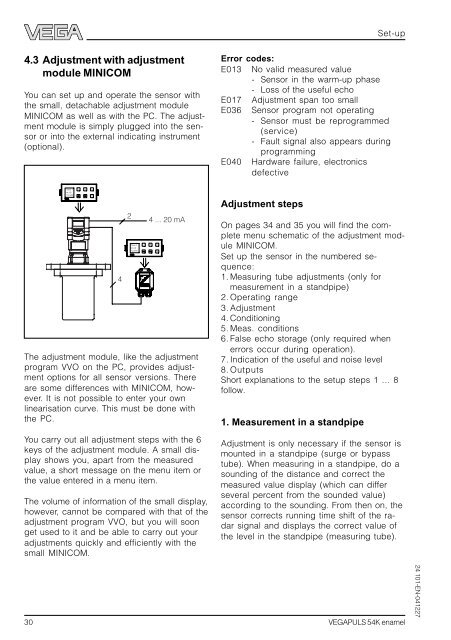
You can set up and operate the sensor with<br />
the small, detachable adjustment module<br />
MINICOM as well as with the PC. The adjustment<br />
module is simply plugged into the sensor<br />
or into the external indicating instrument<br />
(optional).<br />
Tank 1<br />
m (d)<br />
12.345<br />
- + ESC<br />
OK<br />
4<br />
2<br />
Tank 1<br />
m (d)<br />
12.345<br />
4 ... 20 mA<br />
- + ESC<br />
The adjustment module, like the adjustment<br />
program VVO on the PC, provides adjustment<br />
options for all sensor versions. There<br />
are some differences with MINICOM, however.<br />
It is not possible to enter your own<br />
linearisation curve. This must be done with<br />
the PC.<br />
You carry out all adjustment steps with the 6<br />
keys of the adjustment module. A small display<br />
shows you, apart from the measured<br />
value, a short message on the menu item or<br />
the value entered in a menu item.<br />
The volume of information of the small display,<br />
however, cannot be compared with that of the<br />
adjustment program VVO, but you will soon<br />
get used to it and be able to carry out your<br />
adjustments quickly and efficiently with the<br />
small MINICOM.<br />
OK<br />
Error codes:<br />
E013 No valid measured value<br />
- Sensor in the warm-up phase<br />
- Loss of the useful echo<br />
E017 Adjustment span too small<br />
E036 Sensor program not operating<br />
- Sensor must be reprogrammed<br />
(service)<br />
- Fault signal also appears during<br />
programming<br />
E040 Hardware failure, electronics<br />
defective<br />
Adjustment steps<br />
On pages 34 and 35 you will find the complete<br />
menu schematic of the adjustment module<br />
MINICOM.<br />
Set up the sensor in the numbered sequence:<br />
1. Measuring tube adjustments (only for<br />
measurement in a standpipe)<br />
2. <strong>Operating</strong> range<br />
3. Adjustment<br />
4. Conditioning<br />
5. Meas. conditions<br />
6. False echo storage (only required when<br />
errors occur during operation).<br />
7. Indication of the useful and noise level<br />
8. Outputs<br />
Short explanations to the setup steps 1 … 8<br />
follow.<br />
1. Measurement in a standpipe<br />
Set-up<br />
Adjustment is only necessary if the sensor is<br />
mounted in a standpipe (surge or bypass<br />
tube). When measuring in a standpipe, do a<br />
sounding of the distance and correct the<br />
measured value display (which can differ<br />
several percent from the sounded value)<br />
according to the sounding. From then on, the<br />
sensor corrects running time shift of the radar<br />
signal and displays the correct value of<br />
the level in the standpipe (measuring tube).<br />
30 <strong>VEGAPULS</strong> <strong>54K</strong> <strong>enamel</strong><br />
24 101-EN-041227