Operating Instructions - VEGAPULS 54K enamel
Operating Instructions - VEGAPULS 54K enamel
Operating Instructions - VEGAPULS 54K enamel

You also want an ePaper? Increase the reach of your titles
YUMPU automatically turns print PDFs into web optimized ePapers that Google loves.
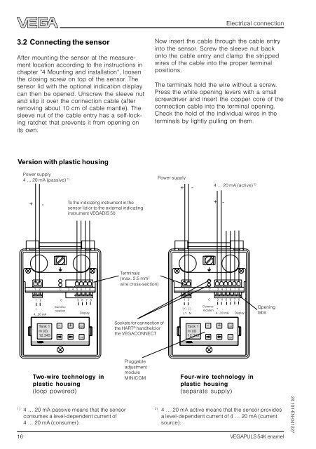
3.2 Connecting the sensor<br />
After mounting the sensor at the measurement<br />
location according to the instructions in<br />
chapter "4 Mounting and installation“, loosen<br />
the closing screw on top of the sensor. The<br />
sensor lid with the optional indication display<br />
can then be opened. Unscrew the sleeve nut<br />
and slip it over the connection cable (after<br />
removing about 10 cm of cable mantle). The<br />
sleeve nut of the cable entry has a self-locking<br />
ratchet that prevents it from opening on<br />
its own.<br />
Version with plastic housing<br />
Power supply<br />
4 … 20 mA (passive) 1)<br />
+ -<br />
1 2 C 3 4 5 6 7 8<br />
1 2 C 5 6 7 8<br />
+ -<br />
4...20 mA<br />
Tank 1<br />
m (d)<br />
12.345<br />
Communication<br />
To the indicating instrument in the<br />
sensor lid or to the external indicating<br />
instrument VEGADIS 50<br />
- + ESC<br />
Display<br />
Two-wire technology in<br />
plastic housing<br />
(loop powered)<br />
1) 4 … 20 mA passive means that the sensor<br />
consumes a level-dependent current of<br />
4 … 20 mA (consumer).<br />
OK<br />
Terminals<br />
(max. 2.5 mm 2<br />
wire cross-section)<br />
Sockets for connection of<br />
the HART ® handheld or<br />
the VEGACONNECT<br />
Pluggable<br />
adjustment<br />
module<br />
MINICOM<br />
Tank 1<br />
m (d)<br />
12.345<br />
- + ESC<br />
Electrical connection<br />
Now insert the cable through the cable entry<br />
into the sensor. Screw the sleeve nut back<br />
onto the cable entry and clamp the stripped<br />
wires of the cable into the proper terminal<br />
positions.<br />
The terminals hold the wire without a screw.<br />
Press the white opening levers with a small<br />
screwdriver and insert the copper core of the<br />
connection cable into the terminal opening.<br />
Check the hold of the individual wires in the<br />
terminals by lightly pulling on them.<br />
Power supply<br />
16 <strong>VEGAPULS</strong> <strong>54K</strong> <strong>enamel</strong><br />
+ -<br />
+ -<br />
1 2 C 3 4 5 6 7 8<br />
1 2 C 3 4 5 6 7 8<br />
(+) (-)<br />
L1 N<br />
4 … 20 mA (active) 2)<br />
Commu-<br />
+ -<br />
nication<br />
4...20 mA Display<br />
Four-wire technology in<br />
plastic housing<br />
(separate supply)<br />
OK<br />
Opening<br />
tabs<br />
2) 4 … 20 mA active means that the sensor provides<br />
a level-dependent current of 4 … 20 mA (current<br />
source).<br />
24 101-EN-041227