Operating Instructions - VEGAPULS 54K enamel
Operating Instructions - VEGAPULS 54K enamel
Operating Instructions - VEGAPULS 54K enamel

Create successful ePaper yourself
Turn your PDF publications into a flip-book with our unique Google optimized e-Paper software.
Emission cone and false echoes<br />
The radar signals are focused by the antenna<br />
system. The signals leave the antenna<br />
in a conical path similar to the beam pattern<br />
of a spotlight. This emission cone depends<br />
on the antenna used.<br />
Any object in this beam cone will reflect the<br />
radar signals. Within the first few meters of<br />
the beam cone, tubes, struts or other installations<br />
can interfere with the measurement. At a<br />
distance of 6 m, the false echo of a strut has<br />
an amplitude nine times greater than at a<br />
distance of 18 m.<br />
At greater distances, the energy of the radar<br />
signal distributes itself over a larger area,<br />
thus causing weaker echoes from obstructing<br />
surfaces. The interfering signals are<br />
therefore less critical than those at close<br />
range.<br />
If possible, orient the sensor axis perpendicularly<br />
to the product surface and avoid<br />
vessel installations (e.g. pipes and struts)<br />
within the 100% emission cone.<br />
If possible, provide a "clear view“ to the<br />
product inside the emission cone and avoid<br />
vessel installations in the first third of the<br />
emission cone.<br />
Optimum measuring conditions exist when<br />
the emission cone reaches the measured<br />
product perpendicularly and when the emission<br />
cone is free from obstructions.<br />
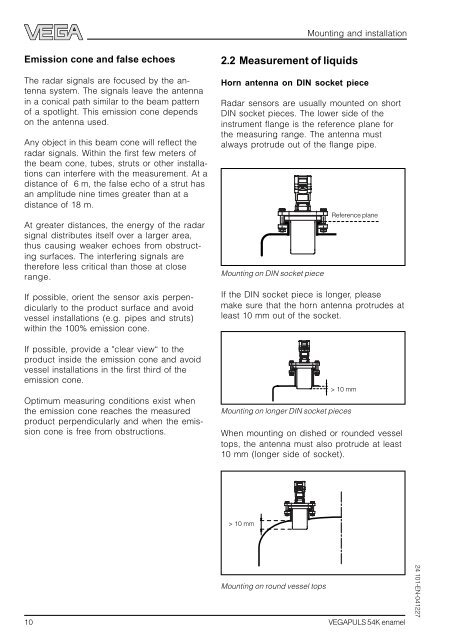
2.2 Measurement of liquids<br />
Horn antenna on DIN socket piece<br />
Radar sensors are usually mounted on short<br />
DIN socket pieces. The lower side of the<br />
instrument flange is the reference plane for<br />
the measuring range. The antenna must<br />
always protrude out of the flange pipe.<br />
Mounting on DIN socket piece<br />
Mounting on longer DIN socket pieces<br />
> 10 mm<br />
Mounting on round vessel tops<br />
Mounting and installation<br />
Reference plane<br />
If the DIN socket piece is longer, please<br />
make sure that the horn antenna protrudes at<br />
least 10 mm out of the socket.<br />
> 10 mm<br />
When mounting on dished or rounded vessel<br />
tops, the antenna must also protrude at least<br />
10 mm (longer side of socket).<br />
10 <strong>VEGAPULS</strong> <strong>54K</strong> <strong>enamel</strong><br />
24 101-EN-041227