Operating Instructions - VEGAPULS 54K enamel
Operating Instructions - VEGAPULS 54K enamel
Operating Instructions - VEGAPULS 54K enamel

Create successful ePaper yourself
Turn your PDF publications into a flip-book with our unique Google optimized e-Paper software.
3.4 Configuration of measuring systems<br />
A measuring system consists of a sensor<br />
with 4 … 20 mA signal output and a unit that<br />
evaluates and further processes the levelproportional<br />
current signal.<br />
On the following pages, you will see a<br />
number of instrument configurations, designated<br />
as "measuring systems“, some of<br />
which are shown with signal processing<br />
units.<br />
4<br />
2<br />
4 … 20 mA<br />
1)<br />
> 250 Ω<br />
Measuring systems in two-wire technology:<br />
4 … 20 mA shown without processing unit<br />
4 … 20 mA on active PLC<br />
4 … 20 mA on active PLC (Ex area),<br />
4 … 20 mA on passive PLC<br />
4 … 20 mA on indicating instrument<br />
VEGADIS 371 Ex<br />
Measuring systems in four-wire technology:<br />
4 … 20 mA shown without signal conditioning<br />
instrument<br />
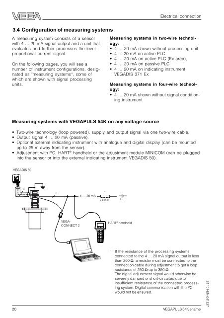
Measuring systems with <strong>VEGAPULS</strong> <strong>54K</strong> on any voltage source<br />
VEGADIS 50<br />
VEGA-<br />
CONNECT 2<br />
20 <strong>VEGAPULS</strong> <strong>54K</strong> <strong>enamel</strong><br />
+<br />
-<br />
HART ® handheld<br />
Electrical connection<br />
Two-wire technology (loop powered), supply and output signal via one two-wire cable.<br />
Output signal 4 … 20 mA (passive).<br />
Optional external indicating instrument with analogue and digital display (can be mounted<br />
up to 25 m away from the sensor).<br />
Adjustment with PC, HART ® handheld or the adjustment module MINICOM (can be plugged<br />
into the sensor or into the external indicating instrument VEGADIS 50).<br />
1) If the resistance of the processing systems<br />
connected to the 4 … 20 mA signal output is less<br />
than 200 Ω, a resistor must be connected to the<br />
connection cable during adjustment to get a loop<br />
resistance of 250 Ω up to 350 Ω.<br />
The digital adjustment signal would otherwise be<br />
severely damped or short-circuited due to<br />
insufficient resistance of the connected processing<br />
system. Digital communication with the PC<br />
would not be ensured.<br />
24 101-EN-041227