AVR STK500 User Guide - Atmel
AVR STK500 User Guide - Atmel
AVR STK500 User Guide - Atmel

You also want an ePaper? Increase the reach of your titles
YUMPU automatically turns print PDFs into web optimized ePapers that Google loves.
3.1 Description of<br />
<strong>User</strong> LEDs<br />
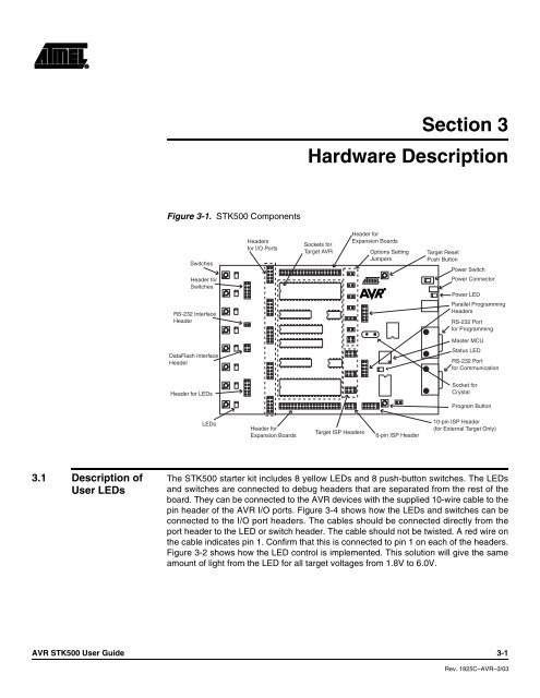
Figure 3-1. <strong>STK500</strong> Components<br />
Switches<br />
Header for<br />
Switches<br />
RS-232 Interface<br />
Header<br />
DataFlash Interface<br />
Header<br />
Header for LEDs<br />
LEDs<br />
Headers<br />
for I/O Ports<br />
Header for<br />
Expansion Boards<br />
Section 3<br />
Hardware Description<br />
Sockets for<br />
Target <strong>AVR</strong><br />
Target ISP Headers<br />
Header for<br />
Expansion Boards<br />
Options Setting<br />
Jumpers<br />
6-pin ISP Header<br />
Target Reset<br />
Push Button<br />
Power Switch<br />
Power Connector<br />
Power LED<br />
Parallel Programming<br />
Headers<br />
RS-232 Port<br />
for Programming<br />
Master MCU<br />
Status LED<br />
RS-232 Port<br />
for Communication<br />
Socket for<br />
Crystal<br />
Program Button<br />
10-pin ISP Header<br />
(for External Target Only)<br />
The <strong>STK500</strong> starter kit includes 8 yellow LEDs and 8 push-button switches. The LEDs<br />
and switches are connected to debug headers that are separated from the rest of the<br />
board. They can be connected to the <strong>AVR</strong> devices with the supplied 10-wire cable to the<br />
pin header of the <strong>AVR</strong> I/O ports. Figure 3-4 shows how the LEDs and switches can be<br />
connected to the I/O port headers. The cables should be connected directly from the<br />
port header to the LED or switch header. The cable should not be twisted. A red wire on<br />
the cable indicates pin 1. Confirm that this is connected to pin 1 on each of the headers.<br />
Figure 3-2 shows how the LED control is implemented. This solution will give the same<br />
amount of light from the LED for all target voltages from 1.8V to 6.0V.<br />
<strong>AVR</strong> <strong>STK500</strong> <strong>User</strong> <strong>Guide</strong> 3-1<br />
Rev. 1925C–<strong>AVR</strong>–3/03