AVR STK500 User Guide - Atmel
AVR STK500 User Guide - Atmel
AVR STK500 User Guide - Atmel

Create successful ePaper yourself
Turn your PDF publications into a flip-book with our unique Google optimized e-Paper software.
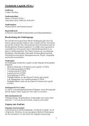
3.3 Connection of<br />
LEDs and<br />
Switches<br />
Figure 3-4. Connection of LEDs and Switches to I/O Port Headers<br />
Hardware Description<br />
Any I/O port of the <strong>AVR</strong> can be connected to the LEDs and switches using the 10-wire<br />
cables. The headers are supplied with VTG (target V CC ) and GND lines in addition to the<br />
signal lines.<br />
3.4 Port Connectors The pinout for the I/O port headers is explained in Figure 3-5. The square marking indicates<br />
pin 1.<br />
Figure 3-5. General Pinout of I/O Port Headers<br />
<strong>AVR</strong> <strong>STK500</strong> <strong>User</strong> <strong>Guide</strong> 3-3<br />
Px0<br />
Px2<br />
Px4<br />
Px6<br />
GND<br />
1 2<br />
PORTx<br />
Px1<br />
Px3<br />
Px5<br />
Px7<br />
VTG<br />
The PORTE/AUX header has some special signals and functions in addition to the<br />
PORTE pins. The pinout of this header is shown in Figure 3-6.<br />
1925C–<strong>AVR</strong>–3/03