AVR STK500 User Guide - Atmel
AVR STK500 User Guide - Atmel
AVR STK500 User Guide - Atmel

You also want an ePaper? Increase the reach of your titles
YUMPU automatically turns print PDFs into web optimized ePapers that Google loves.
3.5 Description of<br />
<strong>User</strong> RS-232<br />
Interface<br />
Hardware Description<br />
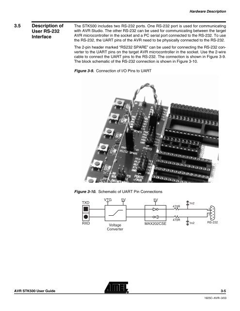
The <strong>STK500</strong> includes two RS-232 ports. One RS-232 port is used for communicating<br />
with <strong>AVR</strong> Studio. The other RS-232 can be used for communicating between the target<br />
<strong>AVR</strong> microcontroller in the socket and a PC serial port connected to the RS-232. To use<br />
the RS-232, the UART pins of the <strong>AVR</strong> need to be physically connected to the RS-232.<br />
The 2-pin header marked “RS232 SPARE” can be used for connecting the RS-232 converter<br />
to the UART pins on the target <strong>AVR</strong> microcontroller in the socket. Use the 2-wire<br />
cable to connect the UART pins to the RS-232. The connection is shown in Figure 3-9.<br />
The block schematic of the RS-232 connection is shown in Figure 3-10.<br />
Figure 3-9. Connection of I/O Pins to UART<br />
Figure 3-10. Schematic of UART Pin Connections<br />
TXD<br />
RXD<br />
VTG 5V<br />
Voltage<br />
Converter<br />
<strong>AVR</strong> <strong>STK500</strong> <strong>User</strong> <strong>Guide</strong> 3-5<br />
5V<br />
MAX202CSE<br />
470R<br />
470R<br />
1n2<br />
1n2<br />
2<br />
3<br />
RS-232<br />
1925C–<strong>AVR</strong>–3/03