Tystar Oxidation & Anneal Furnace Operation - Login | Nanolab, UCLA
Tystar Oxidation & Anneal Furnace Operation - Login | Nanolab, UCLA
Tystar Oxidation & Anneal Furnace Operation - Login | Nanolab, UCLA

Create successful ePaper yourself
Turn your PDF publications into a flip-book with our unique Google optimized e-Paper software.
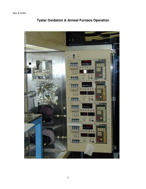
Rev 4/14/04<br />
<strong>Tystar</strong> <strong>Oxidation</strong> & <strong>Anneal</strong> <strong>Furnace</strong> <strong>Operation</strong><br />
1
1.0 INTRODUCTION:<br />
This document covers the operation of <strong>Tystar</strong>'s oxidation and anneal tube (Tube 5) located in<br />
<strong>UCLA</strong>'s Nanoelectronics Research Facility. It sits in the left side bank of 4 tubes each of which<br />
has its own heaters, and closed-loop temperature control, associated quartzware and load<br />
system, and each of which has its own gas flow control system. Tube 5 is a general purpose<br />
tube for anneals, drives and oxidations and does not require the same level of cleanliness as<br />
Tube 1. Tube 5 is also of the older style which uses a process controller rather than tube<br />
computer. The tube numbering and process assignments are as follows:<br />
Right side bank<br />
Topmost tube Tube 1 <strong>Anneal</strong>, Dry & Wet <strong>Oxidation</strong>- Very clean and<br />
lightly doped samples only<br />
2nd Tube from top Tube 2 Silicon Nitride (standard or low stress)<br />
3rd Tube from top Tube 3 Polysilicon (doped or undoped)<br />
Bottom tube Tube 4 Low Temp Oxide (LTO-doped or undoped)<br />
Left Side Bank<br />
Topmost tube Tube 5 <strong>Anneal</strong>, Drive and <strong>Oxidation</strong> for<br />
heavy doped samples<br />
2 nd Tube from top Tube 6 Currently not used<br />
3 rd Tube from top Tube 7 Currently not used<br />
Bottom Tube Tube 8 N2 sinter or Vacuum anneal (350-600C)<br />
This system uses hazardous gases and high temperatures and therefore could cause serious<br />
injury if any action is attempted without THOROUGHLY understanding the system. Refer to<br />
the appendix (LPCVD <strong>Furnace</strong> Shut Down and Emergency Procedures) for safety related<br />
information.<br />
NOTE: While tubes 2,3 and 4 are LPCVD furnaces utilizing vacuum and toxic gases, tube 1<br />
and 5 are atmospheric furnaces that do NOT use a pump or any kind of vacuum. They also do<br />
NOT use any toxic gases and are therefore simpler systems to run than the other tubes. Tube<br />
1 and 5 do use hydrogen and oxygen which are very flammable and potentially explosive<br />
gases, however.<br />
Successful deposition requires extreme cleanliness for anything that goes directly into the tube<br />
or anything that touches anything which goes into the tube. Therefore:<br />
• NEVER touch boats or wafer with your hands even if you are wearing gloves.<br />
Use ONLY the appropriate boat holder. Boat Holder must be clean also.<br />
• Use ONLY clean tweezers or vacuum wand dedicated for that tube. Clean these<br />
implements often using alcohol, DI water and clean wipes.<br />
• ALWAYS clean wafers using either piranah or RCA type clean right before loading<br />
them into the tube. (NOTE: For the LTO tube ONLY a substitute clean for metallized<br />
wafers may be used, otherwise the metal may be attacked.) Wafers must be Clean<br />
and Dry. Use spin rinse dryer whenever possible. Never load a contaminated wafer<br />
or boat into the tube as this will contaminate the tube as well.<br />
• Wafers and boats coming out of the tube are extremely hot. Do NOT set them on<br />
clean wipes, vinyl gloves or anything else which will melt. Set hot items on clean<br />
2
stainless steel bench or on dedicated quartz carrier.<br />
• NEVER store flammable solvents (e.g. squeeze bottles etc.) at the LPCVD load<br />
station; a fire could be started.<br />
• ALWAYS wear a mask when loading and unloading your wafers into tube to<br />
minimize contamination from your breath.<br />
• ALWAYS minimize the time that the boat and loader remains out of the furnace<br />
and makes sure the purge nitrogen is set to 3.5 liters whenever the tube door is<br />
open to keep room air out of the tube.<br />
• ALWAYS store dummy wafers in the tube which they are assigned. Dummy wafers<br />
not needed for a run may be safely stored at the load station in a clean quartz<br />
carrier. Promptly return dummies back to the appropriate tube when your run is<br />
finished. NOTE: Tube 5 does NOT use dummy wafers.<br />
2.0 SUBSTRATE CLEANING:<br />
Wafers going into Tube 5 must be free from organics (e.g. photoresist etc.) and metals and<br />
must have gone through a piranah clean or RCA clean just prior to loading or some other<br />
approved clean (see staff for appropriate clean). Do NOT clean wafers the day before making<br />
a run but rather within 3 hours of beginning a run. For the RCA clean see lab usage guide. For<br />
the piranah clean, consult the piranha clean specification.<br />
3.0 TYMGARD FURNACE CONTROLLER<br />
The oxidation tube consists of a front panel mounted on the load side of the tube and a<br />
remote controller located at the back of the tube. The remote serves as a manual override for<br />
the front controller and should always be in the auto mode (manual light off), otherwise the<br />
front panel will alarm and a recipe cannot be run. If the front panel is not responding to your<br />
commands, verify the remote is in manual mode. If not press the manual button until the light<br />
goes out. The remote unit may also be used to verify gas flow settings. Caution: The scrolling<br />
front panel gas readouts show set points NOT actual flows.<br />
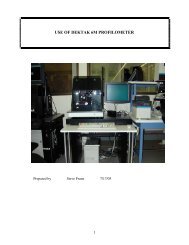
Fig 1 shows the controls and their functions for the front panel. This controller is capable of<br />
storing 23 recipes or 145 program steps not counting Recipe 0. Each recipe is given a<br />
consecutive number 1, 2... 23.<br />
3.1 Idle Mode (Recipe 0)<br />
Recipe 0 is dedicated for the manual or idle mode. This allows valves, boat loader and<br />
temperature to be immediately controlled from Recipe 0 without running a recipe. The idle<br />
mode is also achieved by using Recipe 0. The idle mode is:<br />
3.5L Nitrogen flow (5 liter max)<br />
0 H2H/O2-High hydrogen/oxygen flow ratio (6 liter max high hydrogen<br />
0 H2L/N2-Low hydrogen/nitrogen flow ratio (500 sccm max low hydrogen)<br />
0 O2 Hi-High oxygen flow (3 liter max high oxygen)<br />
0 O2 Lo-Low oxygen flow (500 sccm max low oxygen)<br />
800°C Standby temperature with Auto Temp and Load on<br />
3
The furnace will remain in this mode until either a recipe is run or Recipe 0 is modified. There<br />
is no time limit for recipe 0. Recipe 0 will automatically be entered when a program finishes<br />
running or when the abort key is pressed.<br />
Fig 1 Tube 5 Process Controller<br />
To change the idle mode conditions to 4.5L of N2 at 900°C idle: (NOTE: This is done as an<br />
exercise only; the furnace should normally be left in the idle mode as described above.)<br />
1 Press Program button. (Program lite comes on and LCD asks Recipe ?).<br />
2 Press "0 " followed by "Enter". (This tells the program to work on Recipe 0).<br />
3 The LCD shows "N2 carrier 0000" which is the current nitrogen carrier flow in sccm.<br />
4 Press "Enter" until "N2 3500" is displayed.<br />
5 Press "4500" followed by "Enter" to change N2 flow to 4500 sccm.<br />
6 The display now shows "O2 0000" since there is no oxygen flowing. Press "Enter"<br />
to skip this step.<br />
7 The display now shows "H2/O2 0000" since there is no hydrogen flowing. Press<br />
"Enter" to skip this step.<br />
8 The display now shows "TCA 0000" since no TCA is flowing. Press "Enter" to skip<br />
this step.<br />
9 The display reads "Temp C 800". Press "0900 Enter" to change the temperature to<br />
900°C. (Note the temperature deviation meter to the right of the panel will go<br />
negative and the heater LED will go full on as the furnace immediately begins to<br />
ramp to 900 °C. The display now reads "OFST2..." which is a number<br />
preprogrammed by management and should not be changed. You can continue to<br />
press "Enter" to scroll back through the changes you made. Correct any<br />
mistakes at this time.<br />
10 To exit the Program Mode simply push the Status button. The display will<br />
automatically scroll through the settings as follows:<br />
- R00S01IDLE<br />
4
- N2 carrier 000<br />
- N2 4500<br />
- O2 0000<br />
- H2/O2 0000<br />
- TCA 0000<br />
- Temp C 0900<br />
NOTE: Always exit the Program Mode before leaving the furnace.<br />
12 Following the above procedure change the idle mode back to the initial conditions.<br />
To preview the idle mode conditions:<br />
Either press "Enter" and continue to do so to single step through the recipe. This prevents the<br />
status from automatically scrolling.<br />
OR<br />
Press "Preview" key followed by "0" and "Enter". Press "Enter" again to single step through the<br />
program.<br />
To return to automatic scrolling of status press "Status" key.<br />
3.2 TYMGARD Function Switches (see Fig 1).<br />
ABORT The ABORT switch immediately stops the run sequence and directs control to the<br />
abort step. Each recipe must have an abort step called Step 0. The abort step is executed only<br />
if the ABORT switch is pushed or when the external input is activated. When the abort step is<br />
complete (finished), the TYMGARD returns to the Idle step (recipe 0) conditions.<br />
ALARM ACK Alarms are indicated by a alarm message on the display and by the sounding of<br />
an audible alarm. The ALARM ACK (alarm acknowledge) switch silences the audio alarm. If<br />
there is more than one alarm condition, the ALARM ACK switch can be used to single step<br />
through the display of alarm messages.<br />
EVENT FUNCTION Each of the ten event function switches represents a different relay. Each<br />
will typically be labeled with its function (e.g. N2, O2, etc.). These switches are functional only<br />
during programming. They can be used to directly control the outputs while in the Program<br />
mode of recipe 0 (Manual mode). The LEDs associated with the event switches indicate the<br />
status of the output relays; the LED is on if the relay is on and off if the relay is off.<br />
For the <strong>Nanolab</strong>'s system, the following parameters (events) are programmable<br />
1 N2 : Used to purge the tube with nitrogen (up to 5000 sccm). This<br />
should always be at 3500 sccm during idle or when tube is open to<br />
atmosphere.<br />
2 H2H/O2: Used to control hydrogen/oxygen flow ratio for high hydrogen<br />
flows(up to 6 lpm). See recipe sheets for proper flows.<br />
3 H2L/O2: Used to control hydrogen/oxygen flow ratio for low hydrogen<br />
flows(
important that opening of the Tube be kept as short as possible to<br />
prevent contamination. Use Recipe 0 to Load and Unload your<br />
wafers rather than programming this feature into your recipe.<br />
8 VARITM Instead of having a fixed duration time in a step, any step in a<br />
recipe can have a variable time (VARITM). This allows the operator<br />
to defer the selection (choice) of step time until the recipe is to be<br />
run. When programming a recipe, the VARITM switch is used to<br />
declare a step as having variable time. When the recipe is run, the<br />
TYMGARD will request the fixed time of the VARITM steps. The<br />
operator must enter these times before the recipe actually begins<br />
the RUN sequence. Varitime will usually be used for an oxidation<br />
step.<br />
9 STATUS The STATUS switch is used to place the display in the Status<br />
(automatic scan) mode, where the parameters of the recipe step<br />
currently in progress will be displayed sequentially. These elements<br />
include recipe and step number, time remaining in the recipe, time<br />
remaining in the step, and analog setpoint values. The state of the<br />
relays is always shown on the LEDs.<br />
If TYMGARD is in the Status mode, press the ENTER switch to cause the scan to halt at the<br />
present item. Only this item will be displayed, and its value will change as directed by the<br />
recipe. Press the ENTER switch repeatedly and the display will "single step" through the<br />
status items in the normal scan sequence. Press the STATUS switch again and normal auto<br />
scanning will resume.<br />
10 ENTER The ENTER key inputs numerical data. Whenever a numerical<br />
value is to be entered, the number is specified by using the<br />
numerical keys (1,2,3,4,5,6,7,8,9, or 0), and then input by pressing<br />
the ENTER switch. Also, see the STATUS switch operation given<br />
above.<br />
11 RUN The RUN button is used (pushed) to begin the execution of a<br />
recipe sequence. The display will inquire which recipe is to be run,<br />
RECIPE ?<br />
One of the twenty-three recipes may be selected by pushing a numbered key (1, 2, 3 through<br />
23) followed by pushing the ENTER switch. This begins the execution of the control sequence.<br />
If one or more variable time (VARITM) steps are included in the recipe selected, the recipe<br />
sequence starts after the times are entered.<br />
The RUN LED illuminates when the RUN switch is pushed and remains lit throughout the<br />
recipe, including the abort routine. The RUN LED goes out when the TYMGARD returns to Idle<br />
condition.<br />
12 HOLD When the HOLD function is pushed "on," the LED illuminates and<br />
the counting of time is halted. The counting of time begins again<br />
6
when the HOLD switch is pressed a second time. While the recipe<br />
is on HOLD, it may be edited (see PROGRAM Switch). The HOLD<br />
switch has no other functions. The front panel HOLD switch cannot<br />
override the external hold input; however, if the front panel HOLD<br />
Switch is used in conjunction with external hold, the status display<br />
honors the front panel command.<br />
13 PREVIEW The PREVIEW switch provides the function to view the contents of<br />
a recipe without the ability to change the recipe. When the<br />
TYMGARD is in the Idle mode (no recipe running), PREVIEW may<br />
be used to index through a recipe to preview the sequence and<br />
setpoints. When the TYMGARD is in the Run mode, the<br />
information in the recipe can be viewed without affecting the<br />
currently energized steps or the timing of those steps. The LED is<br />
illuminated when in the Preview mode. The Preview mode may be<br />
exited by pressing PROGRM, STATUS, or the RUN switch. The<br />
Preview mode may be exited without disturbing a recipe sequence<br />
by pressing the STATUS switch.<br />
14 PROGRAM The PROGRM switch places the TYMGARD into the Edit (program)<br />
mode, enabling recipes to be entered or changed. While in the Edit<br />
mode, the TYMGARD display will prompt the operator for recipe<br />
information. The PROGRAM LED illuminates when this mode is<br />
active. The TYMGARD may be set so that a password (code<br />
number) must be entered to activate this mode. To exit the<br />
Program mode, press the PREVIEW or STATUS Switch. PROGRM<br />
and PREVIEW cannot be on at the same time.<br />
15 RAMP The TYMGARD provides for the linear ramping of any analog<br />
setpoint. The RAMP switch is used during the programming of<br />
setpoint information and is used to denote that the setpoint will<br />
change from its previous value to its new value in the amount of<br />
time programmed into the step. All ramp steps must have a<br />
previous step in order to be programmed. Ramp allows the<br />
temperature, for example, to be increased at a fixed rate (usually<br />
slower). If a higher temperature is called for without using Ramp,<br />
the temperature will be raised as fast as possible (~ 10°C/minute)<br />
until the setpoint is reached.<br />
16 UNITS The UNITS switch enables the display to show the engineering<br />
units (e.g., typical units for process control) associated with the<br />
various gas and temperature setpoints instead of the values of the<br />
setpoints normally shown. This feature may be used in the<br />
Program and Preview modes and while the display is scanning<br />
during recipe execution. Press the UNIT switch a second time to<br />
revert the display back to showing setpoint values.<br />
7
4.0 PROGRAMMING<br />
To enter a recipe into memory, the TYMGARD must be in the Programming mode. Recipe 0<br />
and the twenty-three separate recipes are considered as twenty-four separate program<br />
recipes. Most users will be able to input the desired oxidation or anneal time into the desired<br />
recipe and use it. For special cases, it may be necessary to program a separate recipe.<br />
ALL USER RECIPES MUST BE APPROVED BY LAB MANAGEMENT BEFORE RUNNING<br />
THEM.<br />
The TYMGARD can be placed in the Programming mode by depressing the PROGRM<br />
(Program) Switch followed by a recipe number. There is no code number necessary for our<br />
system. The PROGRM LED will illuminate and the first step of the recipe will be shown on the<br />
display. Only the recipe selected may be edited or input at this time. For instance, if the<br />
TYMGARD is in the Program mode for recipe 2, then only the recipe steps for recipe 2 can be<br />
programmed. Once the TYMGARD is in the Program mode, the output information (recipe)<br />
can be programmed for each step.<br />
The TYMGARD is programmed by setting up each individual step. The next step is followed by<br />
the next, one after the other. This step-by-step programming is continued until the entire<br />
recipe is complete. The last step of the recipe is programmed as Step 0 to distinguish it as the<br />
Abort step, without this step the recipe will not run.<br />
There are ten output relay touch switches called the Contact Closure or Event switches along<br />
the right side of the control panel (see Fig 1). Each of these switches corresponds to an output<br />
relay as labeled on the front panel as previously described.<br />
When programming the TYMGARD, the LEDs, which are illuminated, indicate which event<br />
relay is to be energized for the step being programmed.<br />
The Numerical Entry Keys are used to enter recipe numbers, step numbers, the time interval<br />
for each step, and the setpoint values. The numbers for time are keyed into the display as they<br />
are spoken, in hours, minutes, and seconds.<br />
The ENTER Switch will scroll through the specified setpoint outputs. The existing setpoint<br />
value can be left as it is or the value can be changed by entering a new value. The new value<br />
can also be ramped during the step if the RAMP Switch is pushed just before entering a value.<br />
In the Programming Mode, the beginning of each step is noted by the display as<br />
REC.1 STP.01<br />
For Recipe 1, Step 1, the ENTER Switch must be pushed to start the programming of the step<br />
shown in the display. Optionally, a different step number can be requested by pushing the<br />
appropriate number switches, then pushing the ENTER Switch. (NOTE: To advance to the<br />
next step at any time, press "PROGRM" again.) The time for the step will then be displayed.<br />
Enter the time. The display will show the setpoints. Pushing the ENTER switch will cause the<br />
display to show the next setpoint. After the last setpoint is shown, the first setpoint will be<br />
8
displayed again. When the setpoint is shown on the display, it may be changed by pushing the<br />
appropriate number switches. The relay switches may also be pushed to set the relay outputs<br />
that are to be "on" during this step. When Step .01 is complete, step .02 can be reached by<br />
pressing the "PROGRM" Switch.<br />
This programming procedure is repeated until the entire recipe is entered. For the last step, a<br />
zero step is programmed to distinguish it as the Abort step with a time of typically 10 seconds.<br />
Recipe #s 1-14 are reserved for <strong>Nanolab</strong> standard recipes (Recipe Sheets). They are all<br />
oxidation (dry & wet) steps at temperatures of 850, 900, 950, 1000, 1050 and 1100°C<br />
respectively. The oxidation time is kept variable for each of these recipes so that a user may<br />
simply input this time after choosing the desired recipe and after pressing RUN. These recipes<br />
are pre-approved for any user to run.<br />
Consult the dry or wet oxidation curves in the log book to determine oxide thickness. Userprogrammed<br />
recipes (# 15-23) must be approved by the superuser or lab manager and must<br />
be entered in the recipe section of the log book.<br />
Recipe 0 sets the TYMGARD outputs for the conditions desired when a recipe is not running<br />
(Idle mode). This recipe defines the Idle Mode conditions as previously described. For this<br />
example, the process control recipe is recipe number 3.<br />
5.0 TEMPERATURE:<br />
Temperature is a key parameter for oxide growth. Temperature should be +/- 2° C of setpoint<br />
(preferably +/- 1°C). As long as the AUTO TEMP light is on, the temperature is controlled by<br />
the number input through software. If this light is NOT on, the temperature is controlled by the<br />
3 front panel potentiometers and the Temp1/2 switch. With Temp 1, the upper pots control<br />
and with Temp 2 the lower pots control the temperature. There are 3 pots for each group, with<br />
a 4th pot (extreme leftmost) for overtemp. Do NOT adjust the Overtemp pot. Of the remaining<br />
3, the leftmost is for the front zone, the middle for the center zone and the right for the rear or<br />
source zone. An adjustment of 1 on the center zone corresponds to 1 °C while it takes an<br />
adjustment of 10 on the end zones to change by 1°C. When the deviation meter for each zone<br />
is centered, temperature for that zone is at steady state.<br />
The AUTO TEMP mode should always be used so that the preprogrammed recipes control<br />
the temperature (the previously discussed front panel potentiometers are not used). In addition<br />
to the set temperature, TempC, there are 3 software offsets which must be programmed:<br />
TempL (Load or front zone), Offset2 (center zone) and TempS (source or rear zone). TempL<br />
offset and TempS offset must be programmed in EACH step of EACH recipe and is an<br />
experimentally obtained number. The Offset2 offset must be set during recipe 0 for each<br />
temperature (NOT each step or each recipe). Note: If you are running a standard recipe you<br />
should not have to adjust any offset but if you are running at a different temperature or your<br />
own recipe you must take these offsets into account.. These offsets allow one to compensate<br />
for heat loss at the end zones as well as the extra heat added when the torch is on for wet<br />
9
oxidations. Offsets may change slightly from time to time or when the furnace tube is changed.<br />
Consult the log book recipe sheet for latest offsets. Use the preview mode to verify offsets are<br />
correct in the desired recipe. Change them to the log book value if necessary.<br />
When the furnace is opened it is normal for the front zone and center zone to cool off while<br />
the rear zone overheats. Temperature recovery may take up to an hour and these times are<br />
already built into the recipes. Keep in mind that the furnace can be ramped at ~10°C/min while<br />
cooling will be less than 5 °C/min. It is not desirable then to overheat the furnaces.<br />
These furnaces are meant to control between 450-1100°C. Do NOT process outside of<br />
these limits. Additionally, all wet oxide runs must be 800°C - 1100°C.<br />
The center zone should be stabilized (0 on the deviation meter) BEFORE attempting to adjust<br />
the end zones (via TempL or TempS) since the end zones are "slaved" to the center zone.<br />
FURNACE LOADING & UNLOADING:<br />
Although it is possible to incorporate load and unload steps into a recipe, the <strong>Nanolab</strong> prefers<br />
to Load and Unload from Recipe 0 to avoid any possibility of the furnace being open for<br />
prolonged times. There are 2 quartz boats kept in the tube at all times. For 25 wafers or less,<br />
always use the front boat for best uniformity. (Wafers near the rear will see a higher<br />
temperature during wet oxidations due to the torch temperature.) Dummy wafers are not<br />
required, but a clean bare silicon monitor should be run with your wafers to obtain oxide<br />
thickness. Position of these boats on the cantilever is critical; by using the front boat only and<br />
making sure it just touches the rear boat when you load it, you will guarantee proper boat<br />
placement. Face wafers forward with flats facing up. (Although the process does not require<br />
this, it will help us to troubleshoot problems in the future.) To Load your wafers (after fulfilling<br />
all of the aforementioned requirements):<br />
LOADING:<br />
1 Push PROGRAM button (light comes on), 0, ENTER<br />
2 Verify N2 flow is 3500 cc (3.5L/min); change it if necessary<br />
3 Verify Temperature is 800°C with AUTO TEMP on. Change it if necessary.<br />
4 Verify H2H/O2, H2L/N2, O2 Hi and O2 Lo are off.<br />
5 Verify LOAD light is OFF; push button if it is on.<br />
6 Turn on UNLOAD light by pushing UNLOAD button.<br />
7 Cantilever should slowly come out. The speed is determined by lab management<br />
and should be less than 9 inches/minute. Too fast a speed can result in wafer<br />
warpage or slip.<br />
8 When the cantilever is fully extended, use the steel fork to unload the front quartz<br />
boat onto the quartz sled (the steel bench may be used if the sled is not available).<br />
Do NOT set the hot boat on a wipe or anything else which may melt.<br />
9 Load your cleaned substrates (3 or 4 inch) so that each wafer sits in its own slot and<br />
is perpendicular to the boat. Up to 25 wafers may be loaded in this way. Keep all of<br />
the wafer facing forwards with flats all aligned upwards.<br />
10 Using the steel fork, carefully place the boat back onto the cantilever rods so that it<br />
is in front of and just touches the rear boat. Make sure the boat is centered on the<br />
rods.<br />
11 Turn off UNLOAD by pushing button (you must still be in PROGRAM mode.)<br />
12 Turn on LOAD by pressing LOAD button. Light comes on and cantilever slowly<br />
goes into the furnace tube.<br />
10
13 After the cantilever is fully loaded, press "Run" followed by desired Recipe #.<br />
UNLOADING:<br />
1 After finishing your run the alarm will sound. Press the Alarm Acknowledge button<br />
and follow steps 1-12 above to unload your samples and return<br />
system to idle mode. Exit Program mode by pressing STATUS button. Fill out the<br />
Log Book completely and make sure the furnace is in the idle mode with Prgm lite<br />
off.<br />
11