An Investigation of the Impact of Signal Strength on Wi-Fi Link ...
An Investigation of the Impact of Signal Strength on Wi-Fi Link ...
An Investigation of the Impact of Signal Strength on Wi-Fi Link ...

Create successful ePaper yourself
Turn your PDF publications into a flip-book with our unique Google optimized e-Paper software.
4.5.3 Phase 2 Propagati<strong>on</strong> Measurements<br />
Two APs were c<strong>on</strong>figured as “WDS with AP mode” and “AP mode” with E<str<strong>on</strong>g>the</str<strong>on</strong>g>rnet<br />
c<strong>on</strong>necti<strong>on</strong>. The detailed descripti<strong>on</strong> <str<strong>on</strong>g>of</str<strong>on</strong>g> phase 2 measurement is described next.<br />
Scenario 8<br />
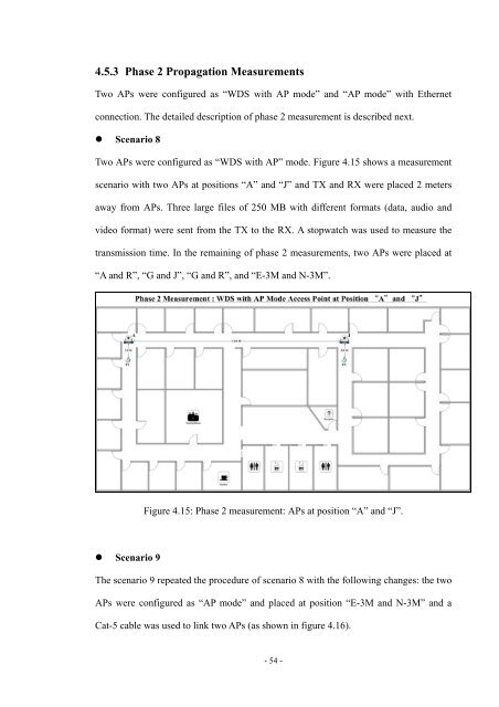
Two APs were c<strong>on</strong>figured as “WDS with AP” mode. <strong>Fi</strong>gure 4.15 shows a measurement<br />
scenario with two APs at positi<strong>on</strong>s “A” and “J” and TX and RX were placed 2 meters<br />
away from APs. Three large files <str<strong>on</strong>g>of</str<strong>on</strong>g> 250 MB with different formats (data, audio and<br />
video format) were sent from <str<strong>on</strong>g>the</str<strong>on</strong>g> TX to <str<strong>on</strong>g>the</str<strong>on</strong>g> RX. A stopwatch was used to measure <str<strong>on</strong>g>the</str<strong>on</strong>g><br />
transmissi<strong>on</strong> time. In <str<strong>on</strong>g>the</str<strong>on</strong>g> remaining <str<strong>on</strong>g>of</str<strong>on</strong>g> phase 2 measurements, two APs were placed at<br />
“A and R”, “G and J”, “G and R”, and “E-3M and N-3M”.<br />
Scenario 9<br />
<strong>Fi</strong>gure 4.15: Phase 2 measurement: APs at positi<strong>on</strong> “A” and “J”.<br />
The scenario 9 repeated <str<strong>on</strong>g>the</str<strong>on</strong>g> procedure <str<strong>on</strong>g>of</str<strong>on</strong>g> scenario 8 with <str<strong>on</strong>g>the</str<strong>on</strong>g> following changes: <str<strong>on</strong>g>the</str<strong>on</strong>g> two<br />
APs were c<strong>on</strong>figured as “AP mode” and placed at positi<strong>on</strong> “E-3M and N-3M” and a<br />
Cat-5 cable was used to link two APs (as shown in figure 4.16).<br />
- 54 -