PDF - 3756 kB - CARNet
PDF - 3756 kB - CARNet
PDF - 3756 kB - CARNet

You also want an ePaper? Increase the reach of your titles
YUMPU automatically turns print PDFs into web optimized ePapers that Google loves.
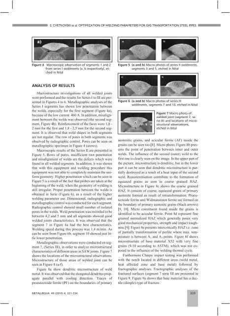
S. CVETKOVSKI et al: OPTIMIZATION OF WELDING PARAMETERS FOR GAS TRANSPORTATION STEEL PIPES<br />
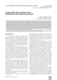
Figure 4 Macroscopic observation of segments 1 and 2<br />
from series I weldments (a, b respectively), etched<br />
in Nital<br />
ANALYSIS OF RESULTS<br />
Macrostructure investigations of all welded joints<br />
were performed and the results for Series I to III are presented<br />
in Figures 4 to 6. Metallographic analyses of the<br />
Series I segments has shown low penetration between<br />
the welds, especially for the first segment (Figure 4a),<br />
because of the low current 460 A. In addition, misalignment<br />
between the welds was observed (the second segment,<br />
Figure 4b). Reinforcement of the faces were 1,8 -<br />
2 mm for the first and 1,8 - 2,5 mm for the second segment.<br />
It is observed that weld shapes in both segments<br />
are not regular. The row of pores in both segments was<br />
observed by radiographic control. Pores can be seen on<br />
metallographic specimen in Figure 4 (arows).<br />
Macroscopic results of the Series II are presented in<br />
Figure 5. Rows of pores, insufficient root penetration<br />
and misalignment of welds are the defects which were<br />
found in all welded segments. In addition, it was shown<br />
that with this equipment and welding procedure this<br />
equipment was not able to completely maintain the uniform<br />
geometry. Higher penetration which can be seen in<br />
Figure 5 is a result of the fact that probes are taken at the<br />
beginning of the weld, when the geometry of welding is<br />
still irregular. Proper penetration between the welds is<br />
obtained in Serie (Figure 6), as a result of the higher<br />
welding parameter use. Dimensional, radiographic and<br />
metallographic control was conducted for each segment.<br />
Radiographic control showed small number of isolated<br />
pores in the welds. Weld penetration was recorded to be<br />
between 4,2 and 5 mm and all segments showed good<br />
welded joints characteristics. It was observed that the<br />
segment 7 in Figure 6a had the best characteristics.<br />
Welding speed during this process was 1,4 m/min. As<br />
can be seen from Figure 6b, segment 10 showed just little<br />
lower penetration.<br />
Metallographic observations were conducted on segment<br />
7, (Series III), in order to analyze microstructural<br />
characteristics of different areas in SAW joints. Figure 7<br />
shows the locations of the microstructural observations.<br />
Microstructure of those areas of welded joint can be<br />
seen in Figure 8 (a-f).<br />
Figure 8a show dendritic microstructure of weld<br />
metal. It was observed that the elongated dendrites propagate<br />
parallel with cooling direction. Traces of<br />
proeutectoide ferrite (PF) on the boundaries of primary<br />
Figure 5 (a and b) Macro photos of series II weldments,<br />
segments 3 and 5, etched in Nital<br />
Figure 6 (a and b) Macro photos of series III<br />
weldments, segments 7 and 10, etched in Nital<br />
Figure 7 Macro photo of<br />
welded joint (segment 7, serie<br />
III) and locations of microstructural<br />
observations,<br />
etched in Nital<br />
austenitic grains, and acicular ferrite (AF) inside the<br />
grains can be seen too 8. Micro photo, Figure 8b presents<br />
the point of penetration between inner and outer<br />
welds. The influence of the second (outer) weld to the<br />
first one is clearly seen on the image. In the upper part of<br />
the picture, microstructure is dendritic, but in the lower<br />
part it can be seen that dendritic microstructure is partially<br />
destroyed as a result of a heat input of the second<br />
weld. Reaustenitisation contribute to the formation of<br />
equiaxed grains as seen in coarse grained HAZ.<br />
Microstructure in Figure 8c shows the coarse grained<br />
HAZ. It consists of coarse, equiaxed grains of primary<br />
austenite formed as result of retransformation. Proeutectoide<br />
ferrite and Widmanstaten ferrite are formed on<br />
the boundary of primary austenitc grains (black arrows)<br />
9, 10. Micro constituent found inside the grains is<br />
identified to be acicular ferrite. Point 8d represent fine<br />
grained normalized HAZ which generally poses very<br />
good mechanical properties, strength and impact toughness<br />
9. Figure 8e presents intercritically HAZ i.e. zone<br />
of partially transformation of perlite where max. temperature<br />
is between A1 and A3 points. Figure 8f shows<br />
microstructure of base material X52 with very fine<br />
grains (9-10 according to ASTM), which was not exposed<br />
to the influence of the welding thermal cycle.<br />
Furthermore Charpy impact testing was performed<br />
with the notch located in different areas (weld metal,<br />
heat affected zone and base metal) followed by<br />
fractographic analyses. Fractographic analyses of the<br />
fractured surfaces (segment 7 serie III are presented in<br />
Figure 9. Figure 9a shows that base material has a ductile<br />
(dimple) type of fracture.<br />
METALURGIJA 49 (2010) 4, 331-334 333