FTA Manual.pdf - Industrial Air
FTA Manual.pdf - Industrial Air
FTA Manual.pdf - Industrial Air

You also want an ePaper? Increase the reach of your titles
YUMPU automatically turns print PDFs into web optimized ePapers that Google loves.
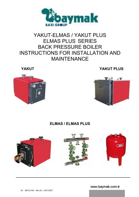
YAKUT-ELMAS / YAKUT PLUS<br />
ELMAS PLUS SERIES<br />
BACK PRESSURE BOILER<br />
INSTRUCTIONS FOR INSTALLATION AND<br />
MAINTENANCE<br />
YAKUT YAKUT PLUS<br />
63 9810.0156 – Rev.04 –12/01/2007<br />
ELMAS / ELMAS PLUS
Convenient Usage According to Conditions<br />
Table of Contents:<br />
1. About the <strong>Manual</strong>………....…….………………............................4<br />
1.1 Contents of the manual……..……………………….............4<br />
1.2 Symbols in the manual...…….……………..........................5<br />
1.3 Users………………………...……………………..................5<br />
2. Safety…..……………………………….……………………………...6<br />
2.1 Convenient Usage According to Conditions……………….6<br />
2.2 General security cautions .….….………………………......6<br />
2.3 Standarts and norms ……..………………………………... 8<br />
2.4 CE marking ........................................................................8<br />
3. Installation…………………...........................................................9<br />
3.1 Delivery Contents ......……………………………........……..9<br />
3.2 Space requirement for Yakut Elmas / Yakut Plus /<br />
Elmas Plus.......................................................................13<br />
3.3 Important Points for Mounting and Mounting Place……..14<br />
3.4 Protection against Corrosion...…………………................16<br />
3.5 Demands Related with Heating System Water….............16<br />
3.6 Gas Blown Burners…………………….......... .........……...17<br />
3.7 Related Demands for fuels that are used.........................17<br />
3.8 Turbulators………….........................................................18<br />
3.9 Before First Start-Up.........................................................19<br />
3.10 Water pressure control .....................................................21<br />
3.11 Control of the hot water tank ...........................................21<br />
3.12 Dimensions of the concrete base......................................22<br />
4. Mounting ...................................................................................23<br />
4.1 Casing mounting Yakut-Elmas/Yakut Plus/Elmas Plus....23<br />
4.2 Burner mounting.........................…………………….....….27<br />
4.3 Explosion cover mounting..……………………..............…30<br />
4.4 Control panel mounting.....…………...........................…..30<br />
5. Installation/System ...................................................................32<br />
5.1 Heating system connection...............................................32<br />
5.2 Control and filling of the system……..…...........................34<br />
5.3 Chimney connection.....................…........................…….37<br />
5.4 Installation of shunt pump.................................................39<br />
2 www.baymak.com.tr<br />
63 9810.0156 – Rev.04 –12/01/2007
Table of Contents:<br />
CAUTION!<br />
6. Operation / Start-up....……........................................................40<br />
6.1 Operation / Start-up ………...............................................40<br />
6.2 Temperatures of installation water....................................41<br />
6.3 Emergency operation... ....................................................42<br />
6.4 Training of operator…....................................................…43<br />
7. Cleaning and maintenance…………………………....................44<br />
7.1 Cleaning.......…………………………………………...........44<br />
7.2 Maintenance…………………………………..……….........46<br />
8. Suggestions for energy saving…….........................................47<br />
8.1 Optimal heating...........................….............……..............47<br />
9. Important Cautions……………………………………….............49<br />
9.1 Important Cautions..........................................................49<br />
10. Technical Data.......................................................................... 51<br />
10.1 Technical Data................................................................51<br />
11. Certificate of Warranty....……………......………………............55<br />
Please read the guide before operating the Boiler . First start-up must be<br />
done by the authorized service.<br />
BAYMAK<br />
MAKİNE SANAYİ VE TİCARET A.Ş.<br />
Tepeören , Akdeniz Caddesi<br />
Orhanlı-Tuzla 34959 İSTANBUL<br />
Tel: (0216) 304 20 44-304 10 88 (pbx)<br />
Fax: (0216) 304 20 13<br />
http:// www.baymak.com.tr<br />
E-mail:yonetim@baymak.com.tr<br />
63 9810.0156 – Rev.04 –12/01/2007<br />
3
About the <strong>Manual</strong><br />
1. About the <strong>Manual</strong><br />
Read the guide carefully before the boiler installation<br />
1.1 Contents of the manual<br />
This manual was prepared for Yakut – Elmas / Yakut Plus / Elmas Plus back pressure<br />
boiler series. The documentary list of the boiler series is on the below. Keep all the<br />
documents in the boiler room!<br />
Documantation Contents Users<br />
Technical Information<br />
Optional Control Panel<br />
<strong>Manual</strong><br />
Instructions for Installation<br />
and Maintenance<br />
63 9810.0156 – Rev.04 –12/01/2007<br />
- Planning document<br />
- Technical data<br />
- Basic supplies and accessories<br />
- Applications<br />
- Parameter table<br />
- Wide processexamples and<br />
their connection plans<br />
- Electrical connection schemes<br />
- Circuit Plans<br />
- Explanation of the Functions<br />
- Programming<br />
- Error and fault tables<br />
- User settings<br />
- Explanation of the Functions<br />
- Programming<br />
- Error and breakdown tables<br />
- User settings<br />
- Convenableusage to norms<br />
- Technical data<br />
- Instructions, Norms, CE<br />
- Cautions for boiler settlement<br />
- Some examples of applications<br />
- First start up<br />
- Mounting/Installation<br />
- Operating<br />
- Cleaning/Maintenance<br />
- Operating<br />
- Cleaning/Maintenance<br />
System Designers<br />
Operaters<br />
Wiring specialists<br />
Operators<br />
Heating system<br />
specialists<br />
Operators<br />
4 www.baymak.com.tr
1.2 Symbols in the manual<br />
1.3 Users<br />
63 9810.0156 – Rev.04 –12/01/2007<br />
About the <strong>Manual</strong><br />
Danger! Negligence of this warning creates danger for<br />
your body and life<br />
Electricshock danger! Negligence of this warning creates<br />
danger for your body and life due to electricshock.<br />
Attention! Negligence of this warning creates danger for<br />
ambient health and device.<br />
.<br />
Warning / Info : You can find special information and<br />
advices here.<br />
Reference to additional information in other documents.<br />
This installation manual is for heating expert who installs the heating system.<br />
5
Safety<br />
2. Safety<br />
63 9810.0156 – Rev.04 –12/01/2007<br />
Danger! Please pay attention to safety rules below.<br />
Otherwise you may risk lifes both yours and others<br />
2.1 Convenient Usage According to Conditions<br />
2.2 General Safety Cautions<br />
For operations with back pressure, these boilers are<br />
equivalent to DIN EN 303 / 304, DIN 4702 section 7.<br />
Danger! Please take into considirations the cautions<br />
on the boiler. Wrong operation of the boiler causes serious<br />
damages.<br />
Applications of first start-up, setting, maintenance<br />
and cleaning must only be done by authorized service.<br />
When breakdowns occur in the heating system,<br />
system must be shut down. Damaged components must be<br />
changed by authorized service stations.<br />
The accesories in the system must be suitable to<br />
technical rules, components in question must be approved<br />
by manufacturer relating to Baymak boiler.<br />
Connections sealed with bolt paint must not be<br />
pulled out by a person who is not expert or member of<br />
service! These seals prove that bolts which is necessary<br />
for perfect and safe operation has not been changed. If<br />
seals get damage, boiler will be out of warranty!<br />
6 www.baymak.com.tr
63 9810.0156 – Rev.04 –12/01/2007<br />
Safety<br />
Alteration, structural cursory modifications and all<br />
similar works are forbidden. These kind of modifications<br />
may be dangerous for people and cause damages on<br />
boiler. In case of neglagence of these subjects, boiler will<br />
be out of warranty.<br />
Obstruction of holes of air ventilation and air relief is<br />
dangerous and forbidden.<br />
Do not place easy explosive and ignitable materials<br />
near to boiler.<br />
Danger in case of gas smell! In case of existing gas<br />
smell, do not operate switches by electricity. Ventilate the<br />
room and shut down gas prevention mechanism. If the<br />
source of the smell can not be found, gas supplier<br />
administration must be informed.<br />
Poisoning Danger! Do not drink heating system<br />
water! Water is not clean due to precipitates.<br />
Caution! Safety valve and air release line must be<br />
open everytime because of water discharge for safety.<br />
Safety valve must be checked occasionally. Safety valve<br />
must be installed onto boiler directly and there must not be<br />
any other valve or equipment. All used equipment must be<br />
in accordance with CE standards.<br />
Electricshock Danger! Before protective hat and<br />
pieces of cover are taken out, all electrical connections on<br />
boiler must be disassembled. Works that will be done when<br />
electric is on, must be carried on by authorized people after<br />
all necessary precuations are supplied.<br />
Please read this manual before using the boiler.<br />
Start-up must be done by authorized service<br />
station. Otherwise boiler will be out of warranty.<br />
7
Safety<br />
2.3 Standarts and Norms<br />
2.4 CE MARKING<br />
63 9810.0156 – Rev.04 –12/01/2007<br />
DIN 4109 Sound insulation in buildings;<br />
requirements and testing<br />
DIN 4755 Technical<br />
installation,<br />
regulation for oil firing<br />
DIN 4756 Gas usage applications for Heating<br />
DIN EN 267 Forced draught oil burners<br />
DIN EN 676 Automatic forced draught burners for<br />
gaseous fuels,<br />
EnEV Determinants of residential space<br />
heating expenditures<br />
DIN EN 12828 Heating systems in buildings ,<br />
DIN EN 12831 Heating systems in buildings design,<br />
DIN 1986 Drainage systems on private ground ,<br />
DIN 18160 Chimneys<br />
DIN 4753 Water heaters and water heating<br />
DIN 4705<br />
installations for drinking water and<br />
service water,<br />
Chimney systems<br />
EN 50165 Electrical equipment of non-electric<br />
appliances for household and similar<br />
purposes<br />
DVGW VP 113 Systems of gas appliances and flue<br />
gas piping<br />
Arrangements of Local Energy and Gas Distrubition<br />
Companies<br />
YAKUT boiler range is certified “CE” by French<br />
Notified Body (CERTIGAZ), satisfying the requirements of<br />
the following directives :<br />
GAD/90/396 CEE, BED/92/42 CEE, LOW VOLTAGE<br />
/73/23 CEE, EMC 89/336<br />
The boilers are tested according the following standards:<br />
EN303/1 - EN303/2 - EN303/3 - EN304 -<br />
EN304/A1<br />
These boilers must be equipped either with a forced<br />
draught gas burner or with a forced draught oil burner ,<br />
recommended by BAYMAK .These burners must be in<br />
conformity with the following standards:<br />
EN267 / EN676. The gas burner must be a EC burner.<br />
BAYMAK declares the conformity of all the<br />
boilers presented in this manual by referring to those<br />
which are tested for CE marking and also to GAD and<br />
BED directives.<br />
8 www.baymak.com.tr
3. Installation<br />
3.1 Delivery Contents<br />
63 9810.0156 – Rev.04 –12/01/2007<br />
Installation<br />
- 1 unit boiler body on transpalet with outside<br />
insulation packed with stretch film<br />
- Coat group in cardboard box that is ready for<br />
mounting, joint package that is necessary for fitting<br />
coat to the boiler.<br />
- Filed user and assemble manuel in boiler package.<br />
- Connection flange, mounted to the boiler, ready for<br />
welding, 2 unit ( Flange fits to boiler easily. There is<br />
no connection flange on Yakut Plus series)<br />
- 2 unit clingrite gasket, in accordance with connection<br />
flanges, mounted to the boiler ( in accordance with<br />
the boiler, There is no clingrite gasket on Yakut Plus<br />
series )<br />
- 8 unit M16x70 bolt, mounted to the boiler, in<br />
accordance with connection flanges.<br />
- 8 unit M16 washer, in accordance with connection<br />
flanges.<br />
- Ceramic wick for insulating the surroundings of<br />
burner (Ø22mm)<br />
- Ceramic blanket for insulating the surroundings of<br />
burner where is inside of the boiler.<br />
- Explosion cover mounted to the boiler,<br />
- Burner Connection Flange mounted to the boiler,<br />
Materials mentioned above are equipments that is<br />
delivered with boiler.<br />
9
Installation<br />
- Boiler body on transport palet with outside insulation. (Boiler is delevered<br />
with its insulation and in a position that is covered by stretch film)<br />
- 2 unit connection flange mounted to the boiler and ready for welding and 8<br />
unit M16x70 bolts, flanges, nuts and washers fitting to the flanges.<br />
10 www.baymak.com.tr<br />
63 9810.0156 – Rev.04 –12/01/2007
63 9810.0156 – Rev.04 –12/01/2007<br />
Installation<br />
- 2 unit clingrite gasket fitting to the connecton flanges mounted on the boiler.<br />
- Ceramic blanket in boiler package for insulation the surroundigs of the boiler.<br />
- Explosion cover mounted to the boiler<br />
11
Installation<br />
63 9810.0156 – Rev.04 –12/01/2007<br />
Yakut/Yakut Plus<br />
Elmas/Elmas Plus<br />
12 www.baymak.com.tr
BOILER<br />
TYPE<br />
3.2 Space Requirement for Yakut Elmas / Yakut Plus / Elmas Plus<br />
Distance between back surface of boiler and wall must be minimum 0.8 meter.<br />
63 9810.0156 – Rev.04 –12/01/2007<br />
ELMAS SERIE<br />
YAKUT SERIE<br />
Installation<br />
YAKUT PLUS<br />
SERIE<br />
YAKUT PLUS<br />
SERIE<br />
10 12 15 18 20 22 25 28 30 35 40 50 55 60 70 80 100 125 160 200 250<br />
X mm 600 600 600 600 750 750 750 750 750 750 1000 1000 1000 1000 1000 1000 1000 1200 1200 1400 1500<br />
Y mm 1500 1500 1500 1500 1500 1500 1500 1500 1500 1500 2000 2000 2000 2000 2000 2000 2200 2300 2300 2500 3000<br />
*) 0.5 meter distance is necessary from the<br />
sides for assembling of side casing.<br />
Besides, if the boiler is settled after assembling of<br />
side casing, this distance may be reduced.<br />
If settlement of boiler is done as burner opens<br />
towards wall, distance between boiler and wall depends on<br />
the burner dimension. Burner cover must be openable at<br />
least 90° to provide the easy cleaning of the boiler and<br />
easy removing process of turbulators.<br />
If burner is opened towards right side, hinge metal bars<br />
of the boiler cover must be installed to right side.<br />
13
Installation<br />
3.3 Important Points for Mounting and Mounting Place<br />
63 9810.0156 – Rev.04 –12/01/2007<br />
Caution! Subjects refering considerations during<br />
mountings related with operations of heating or a tank are<br />
below.<br />
To prevent from water damages that will occure due<br />
to especially water leakages in tank, convenable<br />
precuations must be taken for mounting. Drain lines and<br />
safety system must be suitable and checked periodically<br />
during first start-up and operation.<br />
Ambient where is boiler in must be dry and must not<br />
frost (between 0° and 45°).<br />
Operations about supplying required air to burn the<br />
boiler and discharging waste gas must be in accordance<br />
with CE standards and local distrubition companies that is<br />
responsible from that region.<br />
Place the boiler to a place such as rear balcony,<br />
larder, hall, boiler room. If the boier is in balcony,<br />
protect it from exterior factors. In case of settlement<br />
to bath or laundry, beware boiler not to get wet.<br />
Do not place the boiler to your bedroom!<br />
Settle the boiler onto concrete base. (See page<br />
25). Ambient where is boiler in should not be dusty and<br />
moist.<br />
Settle the boiler to a close place to chimney<br />
channel. Flue, going to chimney, must follow shortest line<br />
using minimum quantity of elbow. Do not install dump onto<br />
pipe. Chimney height must not be over 150 times of<br />
chimney hydraulic diameter.<br />
Chimney outlet must be 1 m. upper than ringe of<br />
roof. Horizontal flues must be connected to chimney with<br />
%5 slant and length must not exceed 1/4 of chimney height<br />
ever.<br />
Mount the chimney connection flue with an<br />
ascending slant towards chimney.<br />
14 www.baymak.com.tr
63 9810.0156 – Rev.04 –12/01/2007<br />
Installation<br />
Please take precuations to protect the boiler from<br />
back flow of water that occured as a result of liquifying of<br />
waste gases.<br />
It is an essential to comply with the procedures and<br />
standards about chimneys that gas distrubition companies<br />
and CE standards stated.<br />
Caution! Mount an air relief device onto outlet pipe<br />
of boiler hot water. <strong>Air</strong> relief device must be installed by<br />
installator company in accordance with installation to the<br />
points where air may be exist on installation except boiler.<br />
Carrying and transportation must be done together<br />
with original packaging material of device considering the<br />
marking on the boiler. Please protect the boiler against<br />
factors that can damage to packaging material and device.<br />
Caution! Check the slants of boiler installation<br />
connetions with a water gauge. After slants have been<br />
done There must not been air in the system. Never use a<br />
valve between expansion valve and the boiler. Set air<br />
pressure in expansion tank depending on system pressure.<br />
Device will be out of warranty in case of setting failure or<br />
undone settings.<br />
Caution! A safety relief valve in accordance with<br />
CE standards must be mounted onto the boiler which was<br />
mentioned in technical data table. There must not be any<br />
valve, armature, diameter reduction, elbow etc between<br />
boiler and safety valve. The boiler will be out of warranty in<br />
case of unconnection and/or wrong connection of safety<br />
valve. At least one unit spare safety valve must be located<br />
onto installation as close to the boiler.<br />
Caution! As the boiler works or in case of operation<br />
of the boiler without water, water must not be pumped to<br />
the boiler directly. The boiler water must be gave at low<br />
temperature when the boiler does not operate. Otherwise<br />
system may come to harm. Cold water must not be<br />
pumped into hot boiler. Otherwise the boiler will be out of<br />
warranty and manufacturer company is not responsible for<br />
physical and sipiritual damages.<br />
15
Installation<br />
3.4 Protection against corrosion<br />
63 9810.0156 – Rev.04 –12/01/2007<br />
Location of the device must be done in accordance<br />
with CE standards to ambients that air current exists.<br />
Physical life of the boiler is 10 years according to<br />
related laws. This period contains service and providing<br />
required spare part duration for executing the functions.<br />
The boiler was produced in accordance with EN<br />
303-1, EN 303-2 and EN 303-3<br />
Caution! Combustion air must not contain elements<br />
that will cause to corrosion. As an example, these gases<br />
are water steams of solution and cleaning substances or<br />
gases in spray boxes.<br />
As boiler of floor heating system which does not<br />
have oxygen insulation in accordance with DIN 4726 is<br />
mounted, exchanger must be used to separate the<br />
installation.<br />
3.5 Demands related with heating system water<br />
To prevent the damages occured as a result of<br />
corrosion in installation, quality of heating water must be as<br />
good as drinking water. Unsuitable waters containing<br />
chemical additive substances or causing to corrosion must<br />
not be used.<br />
16 www.baymak.com.tr
Installation<br />
3.6 Gas Blown Burners<br />
CAUTION! Use only fluid or gas fuel burner that<br />
is avaliable at CE norms. Burner ignition power must be<br />
set according to nominal heat efficiency of boiler.<br />
Please take care boiler mounting manual while<br />
installing boiler.<br />
Burners must be set according to nominal heat<br />
efficiency of boiler on low heat conditions. Power of 1st<br />
stage burner must be upper than 66% of boiler nominal<br />
power for two stage burner.<br />
Waste gas temperature value must not be lower<br />
than 160 °C for ordinary chimney.<br />
Height of chimney must be set properly for<br />
preventing condensation in chimney.<br />
Open the boiler cover and remove some rotarders<br />
from bottom pipes of front plate on required situation<br />
( Note : Number of removed rotarder must not<br />
exceed much more than 25% boiler pipes quantity. )<br />
Installation of suction limitation cover and<br />
additional air mechanism are recommended. Chimney<br />
must be avaliable for processof waste gas at two stage<br />
burner applications.<br />
Explosion cover setup of the boiler must not be<br />
changed and dont put any object to the front side of<br />
cover.<br />
3.7 Related demands for fuels that is used<br />
63 9810.0156 – Rev.04 –12/01/2007<br />
Fuels that is used must be convenable to<br />
defined norms. Otherwise; boiler will be out of<br />
guaranty conditions. Manufacturer company is not<br />
responsible for phisical or sipiritual damages.<br />
Coal gas , natural gas and LPG must be<br />
convenable to EN 437 norm or avaliable for local laws<br />
For fluid fues; Diesel fuel and fuel oil<br />
corresponding to DIN 51603 must be used<br />
Attention ! Fuel-oil and/or heavy oil fuels which is not<br />
in standards can not be used for boilers.<br />
Additive materials are recommended on conditions below<br />
- If they increase durability of fuel storage<br />
- If they increase termic resistance of fuel or reduce<br />
smell formation as tank is filled and provide the burning<br />
without sediment,<br />
Additive material causing sediment or ruin is<br />
forbidden<br />
Attention! It is not allowed to use fuel oil with<br />
Yakut/Elmas 6/8/10 series. Otherwise boiler will be out<br />
of warranty and manufacturer company is not<br />
responsible for physical and sipirutal damages.<br />
17
Installation<br />
3.8 Turbulators<br />
63 9810.0156 – Rev.04 –12/01/2007<br />
All turbulators<br />
must be<br />
reclined to last<br />
point in pipes.<br />
Before installation, check position of whole<br />
turbulators in pipes on front plate. Contact points of<br />
turbulators is head surface of smoke pipe. Assembling and<br />
disassembling of turbulators must be done by operator or<br />
service member.<br />
See picure below for detailed mounting.<br />
18 www.baymak.com.tr
3.9 Before First Start -Up<br />
63 9810.0156 – Rev.04 –12/01/2007<br />
Installation<br />
- Check burner connection of burner and<br />
imperviousness of front and back covers at first.<br />
- Interpose ceramic blanket delivered in cardboard<br />
box between burner tube and door installation.<br />
- Check sittings of sensor end protections to slot they<br />
connected to, whether they are correct or not.<br />
- Be careful while choosing burner and check combustion<br />
setup<br />
- Check connection of water and electrical wiring.<br />
- Check water pressure from manometer. If water is not<br />
enough,add water into the system. Because there is closed<br />
expansion tank in the system, check whether system is<br />
filled or not. It is necessary to be released of air if water<br />
impact voice is coming from system.<br />
- Check tightness of front cover filters after first 24 hours<br />
working. If there is looseness, squeeze them.<br />
- Check the rotation of circulation pump whether it is<br />
right or not. If there is overheating or instant increase for<br />
water temperature, check pump turning direction. If the<br />
problem can not be solved, switch off toggle switch of<br />
burner and call service.<br />
- Set desired boiler thermostat value before ignition<br />
- Beware that ventilation channels are always open.<br />
19
Installation<br />
63 9810.0156 – Rev.04 –12/01/2007<br />
If there is leakage on front cover of the boiler,<br />
tighten the bolt hinge nuts on the cover to overcome.<br />
Do not smoke and light a fire in boiler room. Comply<br />
with operation instructions related with boiler room.<br />
We recommend that make a maintenance<br />
contract with authorized service for providing<br />
regular and proper operation.<br />
Make chimney mounting rightly according to related<br />
standards.Use tape coated aluminium folio or smiliar non<br />
flammable band for providing imperviousness on chimney.<br />
Connect filling and discharging line of expansion<br />
tank. There must not be a valfe on connection pipe<br />
between boiler expansion tank and closed expansion tank.<br />
Otherwise boiler will be out of warranty.<br />
Pull and push explosion cover<br />
on back surface of boiler a few times<br />
by using your hand to check working<br />
situation. Explosion cover was<br />
controlled in factory before<br />
transportation. Explosion cover<br />
regulates operation of boiler when<br />
burner works at first time by opening<br />
towards out. Repeat the operation<br />
control before burner works. See<br />
mounting section for detailed<br />
information for explosion cover<br />
mounting.<br />
20 www.baymak.com.tr
3.10 Control of water pressure<br />
3.11 Control of the hot water tank<br />
63 9810.0156 – Rev.04 –12/01/2007<br />
Installation<br />
Check installation of heating system periodically<br />
before/after/during operation. If water pressure is low fill the<br />
water to heating system.(Maximum value of system<br />
pressure must be marked on manometer by installer<br />
expert)<br />
Installations having boiler tank to store hot water<br />
must be filled by water. Controls of installation must be<br />
done periodically, installation must be carried on by expert<br />
people, operator must get necessary traninigs. Besides,<br />
there must be cold water inlet to the system. An additinal<br />
safety valve must be installed onto heating line at<br />
connection to the boiler tank independently from existing<br />
safety valve.<br />
There must be absolutely a safety valve on the hot<br />
water line. It is adviced to be mounted an expansion valve<br />
fitting to boiler capacity. Boiler will be out of warranty<br />
because of damages stemed from wrong installation<br />
apllications of safety valves.<br />
21
Installation<br />
3.12 Dimensions of the concrete base<br />
Model<br />
63 9810.0156 – Rev.04 –12/01/2007<br />
A<br />
Depth<br />
m<br />
Place boiler onto concreate base according to<br />
dimension<br />
Kazanı<br />
table<br />
aşağıda<br />
given below<br />
ölçüleri verilen bir<br />
beton kaide üzerine yerleştiriniz.!<br />
B<br />
Width<br />
m<br />
Yakut 6 1050 790<br />
Yakut 8 1045 900<br />
Yakut - Elmas 10 1190 920<br />
Yakut - Elmas 12 1190 920<br />
Yakut - Elmas 15 1230 940<br />
Yakut - Elmas 18 1230 940<br />
Yakut - Elmas 20 1410 1000<br />
Yakut - Elmas 22 1410 1000<br />
Yakut - Elmas 25 1410 1000<br />
Yakut - Elmas 28 1660 1050<br />
Yakut - Elmas 30 1660 1050<br />
Yakut - Elmas 35 1660 1050<br />
Yakut - Elmas 40 1687 1220<br />
Yakut - Elmas 50 1687 1325<br />
Yakut - Elmas 55 1687 1325<br />
Yakut - Elmas 60 1687 1325<br />
Yakut - Elmas 70 1925 1325<br />
Yakut - Elmas 80 1925 1325<br />
Yakut - Elmas Plus 100 2004 1650<br />
Yakut - Elmas Plus 125 2530 1950<br />
Yakut - Elmas Plus 160 2530 1950<br />
Yakut - Elmas Plus 200 2600 2100<br />
Yakut - Elmas Plus 250 2939 2600<br />
C<br />
Height<br />
m<br />
22 www.baymak.com.tr<br />
0,10
4. Mounting<br />
63 9810.0156 – Rev.04 –12/01/2007<br />
Mounting<br />
4.1 Casing mounting for Yakut – Elmas / Yakut Plus / Elmas Plus<br />
Please take into consideretion the pictures and<br />
instructions below for boiler casing mounting of Yakut –<br />
Elmas / Yakut Plus / Elmas Plus models.<br />
23
Mounting<br />
- Mount side casing onto boiler body firstly. Side casings are mounted with casette<br />
system. Be sure that channels of side casings was positioned properly.<br />
24 www.baymak.com.tr<br />
63 9810.0156 – Rev.04 –12/01/2007
63 9810.0156 – Rev.04 –12/01/2007<br />
Mounting<br />
- Check the side casings whether<br />
they were positioned onto casette<br />
channels properly.<br />
Mount top-front casing which is<br />
seen from the picture as 1. part<br />
of top casing<br />
25
Mounting<br />
63 9810.0156 – Rev.04 –12/01/2007<br />
Mount second part of top<br />
casing to the first part of top<br />
casing.<br />
Complete casing mounting<br />
installing 3. part of top casing to 1. part<br />
of top casing. Check accordance of<br />
casings with boiler and each other after<br />
casing mounting process.<br />
26 www.baymak.com.tr
4.2 Burner mounting<br />
.<br />
63 9810.0156 – Rev.04 –12/01/2007<br />
Mounting<br />
Take into consideration directions about burner<br />
mounting!<br />
Caution : Burner that is choosen for burner must<br />
have CE Certification. Boiler and burner must be<br />
compatible eachother exactly.<br />
Burner must be choosen by authorized engineer<br />
or manufacturer firm. All parameters which may effect<br />
the accordance between burner and boiler ( boiler<br />
capacity, combustion chamber flame lenght , diameter<br />
of boiler-burner, connection flange, cover thickness)<br />
need to be calculated.<br />
Caution : If there is no CE certification of burner<br />
and if burner is not in accordance with boiler , it will be out<br />
of warranty.<br />
Caution : First start-upmust be made by an<br />
authorized service personel. Otherwise; boiler will be out<br />
of warranty conditions. Manufacturer company is not<br />
responsible for physical or sipiritual damages<br />
Please apply mounting direction defined next pages<br />
for burner mounting application. In case of incompliance of<br />
burner mounting directions, boiler will be out of warranty for<br />
damages that will occure.<br />
Boiler water temperature must be set 55 0 C at gas or<br />
fluid fuels burner mounting<br />
27
Mounting<br />
63 9810.0156 – Rev.04 –12/01/2007<br />
Space between burner tube<br />
and cover ınsulation must be<br />
insulated with ceramic wick and<br />
ceramic blanket given in boiler.<br />
Otherwise boiler will be out of<br />
warranty.<br />
- WRONG APPLICATION<br />
Boiler will be out of<br />
warranty.<br />
- RIGHT APPLICATION<br />
Space between burner<br />
tube and cover ınsulator must<br />
be insulated with seramic wick<br />
and blanket. It is not allowed to<br />
formations of heat transfer and<br />
flame .<br />
28 www.baymak.com.tr
63 9810.0156 – Rev.04 –12/01/2007<br />
Mounting<br />
Boiler-burner connection flange on boiler must be<br />
mounted like picture shown below before the burner<br />
mounting.Place burner insulation material to bottom of<br />
connection flange.<br />
BOILER COVER<br />
CONNECTION BOLTS<br />
BURNER INSULATION<br />
CONNECTION<br />
FLANGE<br />
29
Mounting<br />
4.3 Explosion Cover Mounting<br />
4.4 Control Panel Mounting<br />
63 9810.0156 – Rev.04 –12/01/2007<br />
Check the operating status of<br />
the explosion cover on the rear face of<br />
the boiler with your hand by pulling and<br />
pushing a few times. Exposion cover<br />
regulates the first operation of boiler at<br />
first working moment of the burner by<br />
expanding towards back. Repeat<br />
working control of the explosion cover<br />
before running the burner.<br />
Mount the electirical control panel in accordance<br />
with user manual.<br />
Electricshock Danger! Before protective hat and<br />
pieces of cover is taken out, all electrical connections on<br />
boiler must be disassembled. Works that will be done when<br />
electric is on, must be carried on by authorized people after<br />
all necessary precuations are supplied.<br />
30 www.baymak.com.tr
63 9810.0156 – Rev.04 –12/01/2007<br />
Mounting<br />
Note : In case of usage the immersed thermostate<br />
without using control panel, thermostate must be installed<br />
onto R ½” nipple. It is unsuitable to mount the thermostate<br />
nipple onto collector. This situation may cause dangerous<br />
problems.<br />
Standard thermostat case is under the outlet flange<br />
of the boiler at Yakut Plus – Elmas Plus series.<br />
31
Installation / System<br />
5. Installation/ System<br />
5.1 Heating System Connection<br />
63 9810.0156 – Rev.04 –12/01/2007<br />
Connect the heating system to inlet and outlet of the<br />
boiler.<br />
Mount the filling and discharging connection and its<br />
valve to related connection field at back side of the boiler.<br />
Move the boiler to its operation area and balance it<br />
with the balancing bolts.<br />
Mount the safety equipments connections.<br />
Maximum opening pressure can not be upper than 3<br />
bar (maximum operating pressure).<br />
Connect the safety valves (at inlet and oultet of<br />
boiler), expansion pipes and safety valve in accordance<br />
with the boiler.Ensure that expansion tank is filled by water<br />
and water level and direction of installation is correct. All<br />
pipes must be iron made. Usage of the plastic pipes are<br />
forbidden.<br />
Connect the closed expansion tank and the safety<br />
valve to the boiler properly at the closed heating<br />
installation.Be sure that the expansion tank is full with<br />
water and water pressure is suitable.<br />
Caution: Safety valve must be mounted onto<br />
boiler directly according to related standards. There<br />
must not be any valve, diameter reducer equipment,<br />
pump and these kind of equipments between boiler<br />
and safety valve. Safety valve must be unadjustable<br />
and suitable to CE standards and connection<br />
diameter. There must be a safety valve at tne nearest<br />
point to the boiler on the safety valve installation. In<br />
case of incompliance to the explanations mentioned<br />
on the top, the boiler will be out of warranty and<br />
manufacturer company is not responsible for physical<br />
and sipiritual damages.<br />
32 www.baymak.com.tr
63 9810.0156 – Rev.04 –12/01/2007<br />
Installation / System<br />
The safety valve drainage line must be arranged<br />
when there is no pressure increase and during the time<br />
when safety valve operates. This line must not be<br />
installed against an open place; the drainage end must be<br />
open and tracable. The heating system water coming out at<br />
determined circumstances must be releasing without<br />
danger.<br />
Caution: <strong>Air</strong> release equipments must be placed<br />
to convenient points to release the air that will be<br />
occured during circulation and/or first filling<br />
application.<br />
If these equipments are not mounted to suitable<br />
places or/and equipments whose CE marker is not<br />
available are used, manufacturer company is not<br />
responsible for physical and sipiritual damages.<br />
Caution: The equipments and installation must<br />
be compatible with each other for working correctly<br />
and effectively. All of safety equipments which may<br />
directly effect the operation of boiler must be<br />
covenient with CE standards. If these equipments is<br />
not choosen or placed rightly, manufacturer company<br />
is not responsible for physical and sipiritual damages.<br />
The corrosion resistance of metal materiaI,used at<br />
hot water devices, depends on oxygen that is not exist in<br />
heating water. There will not be any damage after oxygen,<br />
mixed with first or addition water into the system, reacts<br />
with other materials. Transformation of water to black<br />
colour is a sign that there is no free waste oxygen in the<br />
system. Technical rules, especially VDI-Instruction 2035-2,<br />
suggest that heating system needs to be designed and<br />
operated in a way that oxygen inlet is not possible to<br />
heating water.<br />
At the floor heating systems, to prevent intransitive<br />
diffusion of oxygen to pass trough pipe walls, it is<br />
suggested to use plastic pipe which is convenable to DIN<br />
4726. For floor heating systems which is not resistant<br />
against oxygen,system separation must be done by an<br />
exchanger.<br />
33
Installation / System<br />
5.2 Control And Filling of the System<br />
63 9810.0156 – Rev.04 –12/01/2007<br />
Ensure that deliver and flow connections on the<br />
boiler are correct.<br />
Check the leakproof of the system.<br />
Recommended water pressure must be as much as<br />
boiler operation pressure (maximum water pressure can<br />
not be much more than boiler test pressure). For the<br />
control of safety valve and its equipments after checking<br />
the system leakproofness, increase the system pressure<br />
0,5 bar over boiler maximum operation pressure<br />
temporarily. Operation control of the safety valves must be<br />
done under this pressure. The equipment which is inactive<br />
and/or response lately must be changed with a new one<br />
and the tests must be repeated.<br />
Tests must be done absolutely under management<br />
of an expert installer. Otherwise boiler will be out of<br />
warranty and manufacturer will not be responsable for the<br />
damages.<br />
Check the connection line of boiler expansion tank,<br />
ensure that there is no any valve between boiler and<br />
expansion tank.<br />
Pump the water to the central heating unit. This<br />
process must be slowly as much as possible.So, the air in<br />
the installation can be released by the air releasing devices<br />
regularly.<br />
Caution: There must be a standardized CE mark<br />
water filter on the filling line. Otherwise particles or pieces<br />
in the water may be harmful for the system directly or<br />
indirectly.Under these circumstances, boiler will be out of<br />
warranty.<br />
Discharging line and drainage of the safety valve<br />
must be connected to a convenient drainage line and must<br />
be noticable and viewable.<br />
34 www.baymak.com.tr
63 9810.0156 – Rev.04 –12/01/2007<br />
Installation / System<br />
Filling process must be<br />
finished providing convenient<br />
water pressure to the<br />
installation. ( For the convenient<br />
water pressure value, please get<br />
information from authorized<br />
service and installer company’s<br />
authority ).<br />
Water pressure must not<br />
exceed upper than 3 bar<br />
(maximum operation pressure).<br />
Fillling process must be done by<br />
an expert and relief of the air in<br />
installation must be done<br />
correctly.<br />
After the installation is<br />
filled completely, air relief<br />
process must be done and the<br />
air on the pumps must be<br />
released by activating the<br />
pumps at temporary times.<br />
To release the air on the<br />
pump, opening the wet rotor<br />
sleeve as shown, both turning<br />
direction of pump is checked or<br />
air in the pump is relased<br />
Electricshock Danger! Before protective hat and<br />
pieces of cover is taken out, all electrical connections on<br />
boiler must be disassembled. Works that will be done when<br />
electric is on, must be carried on by authorized people after<br />
all necessary precuations are supplied.<br />
35
Installation / System<br />
63 9810.0156 – Rev.04 –12/01/2007<br />
It is suggested that after installation filling and air<br />
ventilation processes are completed, installation pumps<br />
must circulate the water in the system about one hour. It is<br />
neccesary to release last air molecules and activate the<br />
system completely. During the test circulation, pump<br />
and/or pumps must be in use.<br />
Caution: Boiler must not be operated certainly<br />
without providing the water pressure completely and<br />
releasing the air in the installation.<br />
Boiler must be observed for a while after it is<br />
activated, boiler water level must be controlled and<br />
observed constantly by the suitable manometer which<br />
is mounted to a convenable and traceable place in the<br />
installation.<br />
In case of a different pump mounting onto boiler to<br />
provide hot water, circulation lines must be checked<br />
carefully. In case of 4 way valve usage, water heating<br />
installation should be done through another exchanger to<br />
prevent wrong circulation.<br />
Discharging of the Condense Water<br />
Caution! Condense water occured during heating process<br />
must be transferred via an convenable neutralizer<br />
installation(accessory). pH value is between 3 and 4 for<br />
gas fuels and between 2 and 3 for liquid fuels. Therefore<br />
suitable neutralizer must be used.<br />
Condense water line must be installed as slanting.<br />
The line going to channel connection must be seen clearly.<br />
Bottom drainage line must be under the chimney hood<br />
level.<br />
Neutralizer installation is not required for the liquid<br />
fuel which has low rate sulfur (In accordance with ATV note<br />
page A251). Generally , there is no need to neutralizer<br />
installation in the boiler having 200 kW nominal heating<br />
power.<br />
For the neutralization of the boiler outlet water,<br />
local waste water specifications and\or local specifications<br />
must be taken into consideration.<br />
36 www.baymak.com.tr
5.3 Chimney Connection<br />
63 9810.0156 – Rev.04 –12/01/2007<br />
Installation / System<br />
Caution! Waste gas way must be as short as<br />
possible. Waste gas pipes must be installed as in slanting<br />
direction towards chimney and connections must have full<br />
imperviousness.<br />
The chimney must be designed considering<br />
technical specifications determined in DIN 4705 and built<br />
according to DIN 18160.<br />
Both boiler back pressures and boiler pressures<br />
must be in consideration at chimney calculations.<br />
If the waste gas heat is under 160°C in continuous<br />
operating, it is forbidden to use an ordinary chimney.<br />
Warning! ! To change the burner power may effect<br />
waste gas temperature. It is advised to attach an<br />
absorbtion restrictive for high rating exhaust chimneys.<br />
37
Installation / System<br />
63 9810.0156 – Rev.04 –12/01/2007<br />
Interior diameters, heights, heat conduction<br />
resistances and interior faces of chimney systems must be<br />
in the dimensions , fitting to aim of waste gases, which<br />
enables to throw out the chimney gases in every kind of<br />
operation conditions and high pressures in dangerous<br />
levels according to living places must not occur.<br />
There must be at least 20 cm distance between<br />
chimney gas lines and windows in the building.<br />
It is recommended to be consulted to an authorized<br />
establishment about chimney cleaning.<br />
Total resistance value is equal to ∑ζ = 2,2 (sehiedel<br />
diagram) or to 2,5 (plewa diagrams) for direction alteration,<br />
entrance, shape and speed alterations.<br />
∑ζ=2,2 total resistance value is equal to loses of flue<br />
with 2 unit 90º elbow, fixing to chimney with 10º slant, and<br />
an excessive large boiler smoke outlet causing velocity<br />
increase.<br />
45° slant is recommended for inlet of the chimney<br />
gases into the chimney system.<br />
Boiler back pressure and boiler draught<br />
necessity vaules (Pw) must be taken into<br />
consideration at chimney calculations. In case of<br />
usage of wrong calculated chimneys according to<br />
these values or in case of usage of chimneys that has<br />
unsuitable materials, inner boiler and cover insualation<br />
damages (because of wrong burner settings,<br />
overloading, temperature) the device will be out of<br />
warranty<br />
38 www.baymak.com.tr
5.4 Installation of Shunt Pump<br />
63 9810.0156 – Rev.04 –12/01/2007<br />
Installation / System<br />
In case of the drop of the<br />
return water temperature under<br />
55 °C, shunt pump must be<br />
used to supply the return water<br />
at 55°C<br />
In case of usage of the<br />
shunt pump, temperatures of<br />
boiler water was specified at<br />
section of “Temperatures of<br />
Radiator Water” which was<br />
explained on chapter 6.2<br />
Attention In case of drop of the return water<br />
temperature under 55 °C because of installation, shunt<br />
pump must be used to supply return water at 55°C. It is an<br />
essential to use a shunt pump which was calculated at<br />
proper flow quantity and pressure height. Unusage of this<br />
pump or/and usage of a pump that is not suitable, wrong<br />
assembly, falty connections and placement of the pump<br />
may damage to the boiler in long or short term. In case of<br />
these circumstances pump will be out of warranty.<br />
Attention: It is important that installation which<br />
pump connected to must be designed and applied in<br />
accordance with projects and standards. Engineering<br />
calculations must be in accordance with EN installation<br />
design standards.<br />
Attention: As long as device works with shunt<br />
pump, connections of electrical panel and mechanical<br />
installation must be installed by experienced people,<br />
process of first start-up of the device must be done by<br />
authorized technical service. Otherwise the device will be<br />
out of warranty.<br />
Electricshock Danger! Before protective hat and<br />
pieces of cover is taken out, all electrical connections on<br />
boiler must be disassembled. Works that will be done when<br />
electric is on, must be carried on by authorized people after<br />
all necessary precuations are supplied.<br />
39
Operating/Start Up<br />
6. Operation/Start-up<br />
6.1 Operation/Start-up<br />
63 9810.0156 – Rev.04 –12/01/2007<br />
Danger! First start-up must be done by only<br />
authorized service. Before all these applications, expert or<br />
installer of heating system installing and controlling the<br />
installation must check the imperviousness of line, and<br />
declerates the sufficiency of installation to authorized<br />
service. Authorized service checks all parameters that is<br />
necessary for working of the boiler and all substances<br />
mentioned at the top, measures burning values of the<br />
boiler and operates the boiler.<br />
At the unsuitable appications, there is danger risk to<br />
damage to people, envoirement and objects! Devices<br />
which is not started up by authorized services will be out of<br />
warranty and manufacturer company is not responsible for<br />
possible damages.<br />
Attention! It is not allowed heating boiler to be<br />
worked in cicumstances such as building works having<br />
intense dust. Devices may break down.<br />
Injury danger due to hot water! Boiling water may<br />
release from relief valve or drain line for short time when<br />
device is started up.<br />
- Switch on raidator switch.<br />
- Switch on Fuel oil/gas locking mechanism.<br />
- Switch on the switch of boiler line and operating<br />
switch where is on control panel of boiler.<br />
- Arrange essential settings on setup-operating unit<br />
for desired temperature of ambient turning the button.<br />
40 www.baymak.com.tr
6.2 Temperatures of Installation Water<br />
63 9810.0156 – Rev.04 –12/01/2007<br />
Operating/First Start Up<br />
Attention; In this section, essential temperature of<br />
installation is explained for exact and suitable working of<br />
your device. It is very important to match to these<br />
temperatures. Problems occured at the cicumstances<br />
steaming from improper apllications such as liquefying,<br />
chimney, corrosion is out of warranty. Manufacturer<br />
company is not responsible for problems that may occure.<br />
IMPORTANT WARNING ! FOR GAS FUELS<br />
Attention; Minimum boiler inlet water<br />
temperature for gas fuels is limited as 55 °C,<br />
maximum boiler outlet water temperature is limited as<br />
85 °C. Boilers can not be operated out of limits<br />
mentioned. Mentioned inlet water temperatures are<br />
valid in case of shunt pump usage.<br />
IMPORTANT WARNING ! FOR FLUID FUELS;<br />
Minimum boiler inlet water temperature for flue<br />
fuels is limited as 55 °C, maximum boiler outlet water<br />
temperature is limited as 85 °C. Boilers can not be<br />
operated out of limits mentioned. Mentioned inlet water<br />
temperatures are valid in case of shunt pump usage.<br />
FLUID FUEL<br />
USAGE<br />
GAS FUEL<br />
USAGE<br />
Min. Boiler Inlet<br />
Water Temp. o C 55 o C 55 o C<br />
Min. Boiler Outlet<br />
Water Temp. o C 85 o C 85 o C<br />
Attention: Temperature of Boiler inlet must not go down<br />
under 55 o C (Section 5.4.) Otherwise boiler is out of<br />
warranty.<br />
41
Operating/First Start Up<br />
6.3 Emergency Operation<br />
63 9810.0156 – Rev.04 –12/01/2007<br />
When the pressure goes under 0,5 bar or goes<br />
up 1,5 times over opening limit of relief valve (4,5 bar),<br />
boiler must be shut down by applying emergency<br />
operation immediately. Ensure that burner is shut<br />
down and leave boiler for getting cold by itself.<br />
Do not load water to boiler absolutely, open the<br />
door of boiler room and get away from boiler. Call<br />
authorized service immediately.<br />
IMPORTANT WARNING !<br />
Do not load cold water to boiler in any condition.<br />
This situation may cause to important damages and<br />
vital dangers.<br />
Electricshock Danger! Before protective hat and<br />
pieces of cover is taken out, all electrical connections on<br />
boiler must be disassembled. Works that will be done when<br />
electric is on, must be carried on by authorized people after<br />
all necessary precuations are supplied.<br />
As boiler works, in case of circumstances such as<br />
limit exceeding of temperature or/and pressure,<br />
overworking, steam overloading etc., boiler thermostat<br />
must be shut down, pump must go on circulating certainly,<br />
all gas and fuel valves must be shut down, boiler must be<br />
left to get cold by itself. Uncapable and unlicenced people<br />
must not barge to boiler. Opposite conditions may cause<br />
serious life and property losses. The boiler will be out of<br />
warranty in these conditions.<br />
42 www.baymak.com.tr
6.4 Training of Operator<br />
63 9810.0156 – Rev.04 –12/01/2007<br />
Training;<br />
Operating/First Start up<br />
The person who will operate the heating system<br />
must have training in detail about operating of system and<br />
operating forms of safe tools and especially informations<br />
that;<br />
- Not to close or cover of air inlet side;<br />
- Functionality control of explosition cover which is<br />
necessary for good combustion ( See, Explosition cover );<br />
- Not to store ignitable substances and fluids near to<br />
boiler;<br />
- Precuations of control that operator must have;<br />
- Control of water pressure of manometer;<br />
- Control of relief valve drain line;<br />
- Release of installation air;<br />
- To be given the information that “applications made<br />
in regular time periods such as maintenance and cleaning<br />
must be gone on by capable heating system experts” .<br />
Documents;<br />
- Instruction including short information about<br />
operation of boiler must be placed to a close area to boiler.<br />
- As documents related with heating system is<br />
delivered, a warning about necessity of location of these<br />
documents where boiler placed must be declared. (DIN<br />
4756).<br />
43
Cleaning and Maintenance<br />
7. Cleaning and Maintenance<br />
7.1 Cleaning<br />
63 9810.0156 – Rev.04 –12/01/2007<br />
Electricshock Danger! Before protective hat and<br />
pieces of cover is taken out, all electrical connections on<br />
boiler must be disassembled. Works that will be done when<br />
electric is on, must be carried on by authorized people after<br />
all necessary precuations are supplied.<br />
Cleaning consists of items below;<br />
- Cleaning of the boiler from outside,<br />
- Cleaning of combustion chamber and pipes of the<br />
boiler ( this may change depending on operation).<br />
It is strongly advised that cleaning and<br />
maintenance of boiler must be done once in a year by<br />
authorized services.<br />
Attention: Insulation of front cover was made by<br />
a material that is not required to be cleaned. Therefore,<br />
do not clean with any shape or corrosive tool, do not<br />
apply force or pressurized air, do not clean with fluids<br />
like water, etc. In case of damage on cover insulation,<br />
boiler will be out of warranty.<br />
For cleaning of combustion chamber in boiler room,<br />
open boiler cover, pull and take out turbulators with tools<br />
which was delivered with the boiler. After turbulators are<br />
taken out, clean them with a brush and brush holder, clean<br />
smut and dirts accumulating to the side of flume hood<br />
taking out the explotion hoot then repeating all the works<br />
from reverse, assemble explosition hoot and turbulators,<br />
close boiler cover and after bolts are tighten check if there<br />
is gas leakage from connections.<br />
See figure of turbulator assemble for process of<br />
connection and disconnection of turbulators.<br />
Burner must be checked for impurity, cleaned and<br />
processed to maintenance if it is necessary.<br />
In case of necessity, clean boilers from outside.<br />
Use only soft cleaning materials which will not damage to<br />
surface. Cleaning of surfaces, heating the inside of the<br />
boiler and burner, must be only done by authorized<br />
service.<br />
44 www.baymak.com.tr
Assemble of Turbulators :<br />
63 9810.0156 – Rev.04 –12/01/2007<br />
Cleaning and Maintenance<br />
All turbulators must be located into pipe (see figure<br />
below) after related applications are done using related<br />
tools.<br />
All turbulators<br />
must be pushed<br />
till last point<br />
they can go<br />
45
Cleaning and Maintenance<br />
7.2 Maintenance<br />
63 9810.0156 – Rev.04 –12/01/2007<br />
Maintenance applications consist of items below;<br />
- Cleaning and control of insulation points and<br />
connections that water passes through,<br />
- Control of regular operation of safety valves and<br />
cleaning from outside.<br />
- Control of operation pressure and water addition if it<br />
is necessary.<br />
- Releasing of the air in installation<br />
Electricshock Danger! For the purpose of<br />
preventing the electricshock in case of touch, all<br />
pieces on boiler which is necessary to be assembled<br />
(especially plating pieces) must be screwed correctly<br />
after operation is completed.<br />
Danger! Maintenance applications must be made by<br />
an authorized installation expert. Please do not try to make<br />
these applications by yourself. Otherwise you may face off<br />
with dangerous situations.<br />
Maintanence Agreement<br />
Maintananence of Heating system installation<br />
should be done properly according to local standards. It is<br />
suggested heating system installation to have complete<br />
maintanence process once in a year. If an agrement is<br />
done with authorized service for maintenance, boiler life<br />
extends and this provides heating system to be operated<br />
for long years economically and safely.<br />
46 www.baymak.com.tr
Suggestions for Energy Saving<br />
8. Suggestions for Energy Saving<br />
8.1 Optimal Heating<br />
63 9810.0156 – Rev.04 –12/01/2007<br />
BAYMAK Boilers proved themselves with their<br />
specialities of economical consumption and perfect energy<br />
savings as long as their regular maintenance goes on.<br />
You can be effective at the factors of energy saving.<br />
For this purpose, we would like to suggest some useful<br />
information to provide much more saving.<br />
Ambient Temperature<br />
• Do not set room (ambient) temperature higher than it<br />
has to be. Each one degree will increase energy<br />
consumption %6.<br />
• Beware ambient temperature to be in accordance with<br />
process type. You can set each raditor in the room by<br />
their termostat valves independently.<br />
Suggestions about temperature of various ambients are;<br />
Bath………………………………………..22 0 C – 24 0 C<br />
Sitting rooms……………………………... ……… 20 0 C<br />
Bed rooms ……………………………….16 0 C - 18 0 C<br />
Kitchen …………………………………...18 0 C - 20 0 C<br />
Hallway/Other rooms …………………...16 0 C - 18 0 C<br />
• Reduce room temperature 4 – 5 °C during night and when<br />
you are not in the home.<br />
• When you cook something, kitchen warms up nearly by<br />
itself. To save energy, take the advantage of heat coming<br />
from oven and dish washer machine.<br />
• Do not set thermostate repeatly! If you do not heat a room<br />
because it is not used, the room spread the heat from cell,<br />
wall and doors to other rooms. Because radiator capacity is<br />
not enough to supply this additional heat, they do not work<br />
economically.<br />
47
Suggestions for Energy Saving<br />
63 9810.0156 – Rev.04 –12/01/2007<br />
• Beware that there is no curtain, cupboad etc. infront of<br />
radiators. This situation effects heat transfer to room badly.<br />
Convenable Setting According to <strong>Air</strong> Conditions<br />
In case of operation position with a panel combined<br />
with sensor sensing outside temperature, your heating system<br />
is adjusted according to outer air conditions.<br />
Ventilation<br />
For purpose of providing a comfort climate ambient and<br />
preventing from formatin of fungus on walls, regular ventilation<br />
of the heated rooms is very improtant. Barely, right ventilation<br />
is important to prevent cost loss steming from undesired<br />
energy loss.<br />
• Open window completely but do not wait much more than<br />
10 minutes. So, you can provide enough air ventialation<br />
without cooling the room.<br />
• Ventilation: Open the window a few times in a day between<br />
4 and 10 minutes.<br />
• <strong>Air</strong> current: Open all windows and doors in the room 2 or 4<br />
times in a day.<br />
Maintenance<br />
Before winter term starts, get maintenance of boiler<br />
done ! If maintenance and cleaning of the device is done at<br />
autumn term, this is in optimum situation as heating term.<br />
48 www.baymak.com.tr
9. Important Cautions<br />
9.1 Important Cautions<br />
63 9810.0156 – Rev.04 –12/01/2007<br />
Important Cautions<br />
Subjects related with product warranty<br />
conditions that consumer must consider:<br />
Product warranty document that was given by<br />
Baymak A.S. does not contain breakdowns and damages<br />
which occur because of usage in conditions that is not<br />
normal.<br />
By depending on this matter, items below including<br />
warranty conditions is presented to your attention. You can<br />
find the conditions that warranty is not valid in these items:<br />
1. Get your warranty, belonging to your product ,<br />
aprroved to your authorized dealer<br />
2. If there is no approvals of authorized seller and<br />
dealer that has to be on warranty document or if<br />
original serial number on waranty document is<br />
erased by scraping-damaging,<br />
3. Breakdowns and damages that usage faults caused,<br />
(Please use your device applying applications<br />
described on your manual)<br />
4. Occured damages during transport to customer<br />
after delivery date.<br />
5. Breakdowns occuring because of insufficient<br />
antifreeze (freezing etc.)<br />
6. Except authorized service experts, other people<br />
must not intervene to device for any reason.<br />
7. Problems that will occur because of<br />
unaccomplished maintenance and control that is<br />
neccesary to be done,<br />
49
Important Cautions<br />
63 9810.0156 – Rev.04 –12/01/2007<br />
8. Responsibles for delivery of warranty documents are<br />
seller, agent, dealer or represantative that was<br />
purchased from.<br />
9. Wrong location, wrong piping fitings, wrong capacity<br />
choice, installation pressure over 4 atu, insufficient<br />
chimney system, low or high voltage, safety<br />
thermostate, thermometer, altered burner settings,<br />
wrong heating system installation, external physical<br />
or chemical factors, breakdowns because of<br />
tranportation or storage conditions, usage of<br />
unsuitable fuel.<br />
10. Repair or alterations that is not done by authorized<br />
service team.<br />
11. Customer is responsible in case of excesive<br />
installation pressure or water leakage from<br />
installation fittings.<br />
12. Problems because of insufficient soot cleaning,<br />
plugged nozzle, materials damaged from fuel are out<br />
of warranty.<br />
13. Boiler will be out of warranty because of breakdowns<br />
and damages occured because there is no water in<br />
boiler, unconnected equipment that has to be<br />
mounted to the installation, missing or wrong<br />
mounting, usage of equipment which is<br />
unconvenient (i.e. safety valve), leaving the boiler to<br />
have steam, pumping the limy water<br />
14. A safety valve which is suitable according to<br />
standards must be mounted onto boiler. Boiler will<br />
be out of warranty if safety valve is not mounted or<br />
there is valve, pipe, elbow between safety valve and<br />
boiler.<br />
15. Damages related with liquifying point corrosion<br />
occured because boiler or return water temperature<br />
is very low and damages that operation with<br />
uconvenient filling and addition water caused are out<br />
of warranty.<br />
50 www.baymak.com.tr
10. Technical Data<br />
10.1 Technical Data<br />
63 9810.0156 – Rev.04 –12/01/2007<br />
Technical Data<br />
51
Technical Data<br />
INSTALLATON SCHEMA OF CENTRAL HEATING SYSTEM<br />
Attention! Schema is for guidence. Location of installation and equipments may vary<br />
according to condition of installation.<br />
At Yakut-Elmas boiler series, expansion tank connection must be done from nearest point,<br />
an convenable safety valve must be connected onto safety flange on boiler.<br />
52 www.baymak.com.tr<br />
63 9810.0156 – Rev.04 –12/01/2007<br />
Expansion tank return
63 9810.0156 – Rev.04 –12/01/2007<br />
Technical Data<br />
INSTALLATION DEFINITION OF CENTRAL HEATIG SYSTEM SCHEMA<br />
1 BOILER<br />
2 BURNER<br />
3 BOILER WATER OUTLET PIPE<br />
4 BOILER WATER INLET PIPE<br />
5 INSTALLATION OUTLET COLLECTOR<br />
6 CIRCULATION PUMP<br />
7 GATE VALVE<br />
8 MANOMETER<br />
9 AIR RELIEF NIPPLE<br />
10 HEATING GROUPS<br />
11 INSTALLATION INLET COLLECTOR<br />
12 OPEN EXPANSION TANK<br />
13 OPEN EXPANSION TANK OUTLET PIPE<br />
14 BOILER OUTLET PIPE TO OPEN EXPANSION VALVE<br />
15 FILLING-DISCHARGING PIPE OF BOILER WATER<br />
16 CONDENSE PIPE<br />
17 BOILER THERMOSTATE CASE<br />
18 CLEANING COVER<br />
19 EXPLOSION COVER<br />
20 FLUE<br />
CLOSED EXPANSION VALVE (AVAILABLE WITH ELMAS SERIES)BOILERS<br />
21<br />
22<br />
SAFETY VALVE (SAFETY VALVE IS MOUNTED BY INSTALLER IN ACCORDANCE<br />
WITH INSTALLATION)<br />
53
Technical Data<br />
54 www.baymak.com.tr<br />
63 9810.0156 – Rev.04 –12/01/2007
63 9810.0156 – Rev.04 –12/01/2007<br />
Warranty Document<br />
55
Warranty Document<br />
56 www.baymak.com.tr<br />
63 9810.0156 – Rev.04 –12/01/2007