Single Reduction & Single Reduction with Differential Lock - Spicer
Single Reduction & Single Reduction with Differential Lock - Spicer
Single Reduction & Single Reduction with Differential Lock - Spicer

You also want an ePaper? Increase the reach of your titles
YUMPU automatically turns print PDFs into web optimized ePapers that Google loves.
Remove <strong>Differential</strong> Carrier<br />
Procedure -<br />
9<br />
1. Block the vehicle.<br />
2. Drain axle lubricant.<br />
3. Disconnect main driveline.<br />
4. Disconnect differential lockout air line.<br />
5. Disconnect lead wires to the selector switch and air<br />
line at shift cylinder.<br />
6. Remove axle shafts.<br />
Diff-<strong>Lock</strong> Models<br />
For removal of the locking wheel differential carrier<br />
assembly, the differential lock must be engaged and<br />
held in the engaged position. This can be accomplished<br />
by one of two methods; either engage via air<br />
pressure or engage manually.<br />
Engage via Air Pressure<br />
Using an auxiliary air line, apply 80–120 PSI air pressure<br />
to shift cylinder air port to engage clutch.<br />
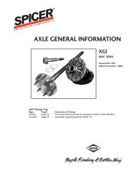
Engage Manually<br />
1<br />
1—Connect 80-120 PSI air line to cylinder port<br />
Install a .250 – 18 NPTF bolt over 1.5" long in the<br />
cylinder air port to manually engage the clutches.<br />
GM models require a M12 X 1.5 X 38mm bolt.<br />
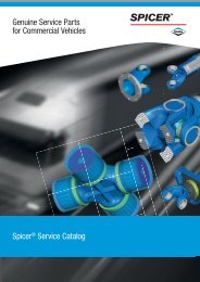
<strong>Differential</strong> Carrier<br />
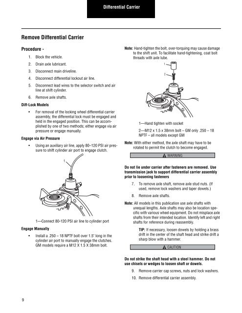
Note: Hand-tighten the bolt, over-torquing may cause damage<br />
to the shift unit. To facilitate hand-tightening, coat bolt<br />
threads <strong>with</strong> axle lube.<br />
1<br />
1—Hand tighten <strong>with</strong> socket<br />
2—M12 x 1.5 x 38mm bolt – GM only .250 – 18<br />
NPTF – all models except GM<br />
Note: With either method, the axle shaft may have to be<br />
rotated to permit the clutch to become engaged.<br />
Do not lie under carrier after fasteners are removed. Use<br />
transmission jack to support differential carrier assembly<br />
prior to loosening fasteners<br />
7. To remove axle shaft, remove axle stud nuts. (If<br />
used, remove lock washers and taper dowels.)<br />
8. Remove axle shafts.<br />
2<br />
WARNING<br />
Note: All models in this publication use axle shafts <strong>with</strong><br />
unequal lengths. Axle shafts may also be location specific<br />
<strong>with</strong> various wheel equipment. Do not misplace axle<br />
shafts from their intended location. Identify left and right<br />
shafts for reference during reassembly.<br />
TIP: If necessary, loosen dowels by holding a brass<br />
drift in the center of the shaft head and strike drift a<br />
sharp blow <strong>with</strong> a hammer.<br />
CAUTION<br />
Do not strike the shaft head <strong>with</strong> a steel hammer. Do not<br />
use chisels or wedges to loosen shaft or dowels.<br />
9. Remove carrier cap screws, nuts and lock washers.<br />
10. Remove differential carrier assembly.