Single Reduction & Single Reduction with Differential Lock - Spicer
Single Reduction & Single Reduction with Differential Lock - Spicer
Single Reduction & Single Reduction with Differential Lock - Spicer

Create successful ePaper yourself
Turn your PDF publications into a flip-book with our unique Google optimized e-Paper software.
Install and Adjust <strong>Differential</strong> <strong>Lock</strong> - Type<br />
2 Axles Continued<br />
Procedure -<br />
41<br />
1. Install selector switch in cylinder cover. Torque<br />
switch to 10-12 lbs.ft (14-16 N•m).<br />
Note: Effective July 1, 1996, Dana will standardize on the<br />
selector switch and wiring harness. Reference Bulletin<br />
ABIB-9609. Types 1 and 2 switches <strong>with</strong> 12 mm threads<br />
will be discontinued. The selector switch and wiring harnesses<br />
are interchangeable <strong>with</strong> each other.<br />
Check Selector Switch Operation: Check switch electrically<br />
<strong>with</strong> an ohmmeter or continuity tester. Switch should close<br />
(show continuity) when clutches are engaged and should<br />
open (no continuity) when clutches are disengaged<br />
Install <strong>Differential</strong> Carrier Assembly in Axle Housing: The<br />
differential lock must be engaged and held in the engaged<br />
position for installation of carrier assembly in axle housing.<br />
This can be accomplished by one of the following two methods:<br />
Air Pressure Engagement: Using an auxiliary air line,<br />
apply 80-120 psi air pressure to shift cylinder air port to<br />
engage clutch.<br />
Manual Engagement: Install an M12x1.5 bolt, over<br />
38mm (1.5") long, in the cylinder air port to manually<br />
engage the clutches<br />
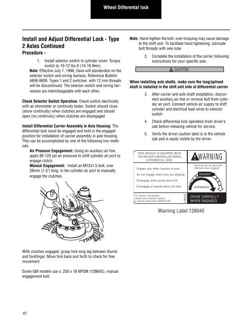
With clutches engaged, grasp fork long leg between thumb<br />
and forefinger. Move fork back and forth to check for free<br />
movement.<br />
Some GM models use a .250 x 18 NPSM (128642), manual<br />
engagement bolt.<br />
Wheel Differental lock<br />
Note: Hand-tighten the bolt, over-torquing may cause damage<br />
to the shift unit. To facilitate hand tightening, lubricate<br />
bolt threads <strong>with</strong> axle lube.<br />
2. Complete the installation of the carrier following<br />
instructions for your specific axle.<br />
CAUTION<br />
When installing axle shafts, make sure the long/splined<br />
shaft is installed in the shift unit side of differential carrier<br />
3. After carrier and axle shaft installation, disconnect<br />
auxiliary air line or remove bolt from cylinder<br />
air port. Connect vehicle air supply to shift<br />
cylinder and electrical lead wires to selector<br />
switch<br />
4. Check differential lock operation from driver’s<br />
cab before releasing vehicle for service.<br />
5. Verify the driver caution label is in the vehicle<br />
cab and is easily visible by the driver.<br />
THIS VEHICLE IS EQUIPPED WITH<br />
THE DRIVER CONTROLLED WHEEL<br />
DIFFERENTIAL LOCK.<br />
Engage only when traction is poor<br />
Do not engage when tires are slipping<br />
Disengage when going down hill<br />
Disengage at speeds above 25 mph<br />
For further information<br />
consult your owners manual<br />
or <strong>Spicer</strong> publication AXDR-0130<br />
128045<br />
WARNING<br />
Steering will be adversely<br />
affected when engaged<br />
ENGAGED<br />
DISENGAGED<br />
DRIVE CARFULLY<br />
WHEN ENGAGED<br />
Warning Label 128045