Single Reduction & Single Reduction with Differential Lock - Spicer
Single Reduction & Single Reduction with Differential Lock - Spicer
Single Reduction & Single Reduction with Differential Lock - Spicer

Create successful ePaper yourself
Turn your PDF publications into a flip-book with our unique Google optimized e-Paper software.
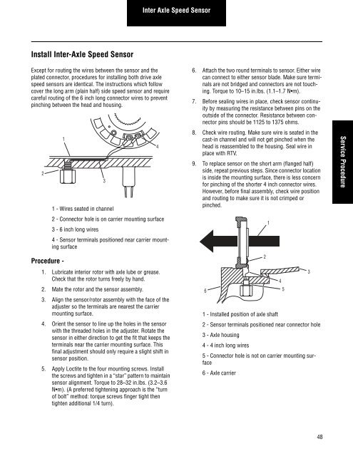
Install Inter-Axle Speed Sensor<br />
Except for routing the wires between the sensor and the<br />
plated connector, procedures for installing both drive axle<br />
speed sensors are identical. The instructions which follow<br />
cover the long arm (plain half) side speed sensor and require<br />
careful routing of the 6 inch long connector wires to prevent<br />
pinching between the head and housing.<br />
2<br />
Procedure -<br />
1<br />
3<br />
1 - Wires seated in channel<br />
2 - Connector hole is on carrier mounting surface<br />
3 - 6 inch long wires<br />
4 - Sensor terminals positioned near carrier mounting<br />
surface<br />
1. Lubricate interior rotor <strong>with</strong> axle lube or grease.<br />
Check that the rotor turns freely by hand.<br />
2. Mate the rotor and the sensor assembly.<br />
3. Align the sensor/rotor assembly <strong>with</strong> the face of the<br />
adjuster so the terminals are nearest the carrier<br />
mounting surface.<br />
4. Orient the sensor to line up the holes in the sensor<br />
<strong>with</strong> the threaded holes in the adjuster. Rotate the<br />
sensor in either direction to get the fit that keeps the<br />
terminals near the carrier mounting surface. This<br />
final adjustment should only require a slight shift in<br />
sensor position.<br />
5. Apply Loctite to the four mounting screws. Install<br />
the screws and tighten in a “star” pattern to maintain<br />
sensor alignment. Torque to 28–32 in.lbs. (3.2–3.6<br />
N m). (A preferred tightening approach is the “turn<br />
of bolt” method: torque screws finger tight then<br />
tighten additional 1/4 turn).<br />
Inter Axle Speed Sensor<br />
4<br />
6. Attach the two round terminals to sensor. Either wire<br />
can connect to either sensor blade. Make sure terminals<br />
are not bridged and connectors are not touching.<br />
Torque to 10–15 in.lbs. (1.1–1.7 N m).<br />
7. Before sealing wires in place, check sensor continuity<br />
by measuring the resistance between pins on the<br />
outside of the connector. Resistance between connector<br />
pins should be 1125 to 1375 ohms.<br />
8. Check wire routing. Make sure wire is seated in the<br />
cast-in channel and will not get pinched when the<br />
head is reassembled to the housing. Seal wire in<br />
place <strong>with</strong> RTV.<br />
9. To replace sensor on the short arm (flanged half)<br />
side, repeat previous steps. Since connector location<br />
is inside the mounting surface, there is less concern<br />
for pinching of the shorter 4 inch connector wires.<br />
However, before final assembly, check wire position<br />
and routing to make sure it is not crimped or<br />
pinched.<br />
6<br />
1 - Installed position of axle shaft<br />
2 - Sensor terminals positioned near connector hole<br />
3 - Axle housing<br />
4 - 4 inch long wires<br />
5 - Connector hole is not on carrier mounting surface<br />
6 - Axle carrier<br />
2<br />
1<br />
4<br />
5<br />
3<br />
48<br />
Service Procedure