Single Reduction & Single Reduction with Differential Lock - Spicer
Single Reduction & Single Reduction with Differential Lock - Spicer
Single Reduction & Single Reduction with Differential Lock - Spicer

Create successful ePaper yourself
Turn your PDF publications into a flip-book with our unique Google optimized e-Paper software.
Install and Adjust Wheel <strong>Differential</strong> <strong>Lock</strong><br />
Note: With differential carrier completely assembled and<br />
adjusted, install differential lock as follows:<br />
Procedure -<br />
1. Install fixed curvic clutch on splined hub of flanged<br />
differential case, then install snap ring.<br />
2. If shift fork and sliding curvic clutch are disassembled,<br />
engage fork <strong>with</strong> clutch hub and install spring<br />
pin in the long leg of the fork. See illustration for fork<br />
mounting position on clutch.<br />
3. Position compression spring, shift fork and clutch<br />
assembly in shift opening of the carrier. Align pilot<br />
hole of shift fork <strong>with</strong> pilot hole of carrier. Install<br />
pushrod, engaging shift fork head, and compression<br />
spring in carrier.<br />
4. Install new O-ring on piston.<br />
5. Lubricate piston and O-ring <strong>with</strong> silicone grease and<br />
install piston assembly in cylinder. Position piston<br />
<strong>with</strong> small diameter hub toward closed end of cylinder.<br />
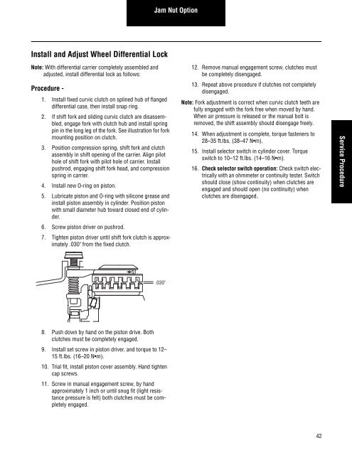
6. Screw piston driver on pushrod.<br />
7. Tighten piston driver until shift fork clutch is approximately<br />
.030" from the fixed clutch.<br />
8. Push down by hand on the piston drive. Both<br />
clutches must be completely engaged.<br />
9. Install set screw in piston driver, and torque to 12–<br />
15 ft.lbs. (16–20 N m).<br />
10. Trial fit, install piston cover assembly. Hand tighten<br />
cap screws.<br />
11. Screw in manual engagement screw, by hand<br />
approximately 1 inch or until snug fit (light resistance<br />
pressure is felt) both clutches must be completely<br />
engaged.<br />
Jam Nut Option<br />
.030"<br />
12. Remove manual engagement screw, clutches must<br />
be completely disengaged.<br />
13. Repeat above procedure if clutches not completely<br />
disengaged.<br />
Note: Fork adjustment is correct when curvic clutch teeth are<br />
fully engaged <strong>with</strong> the fork free when moved by hand.<br />
When air pressure is released or the manual bolt is<br />
removed, the shift assembly should disengage freely.<br />
14. When adjustment is complete, torque fasteners to<br />
28–35 ft.lbs. (38–47 N m).<br />
15. Install selector switch in cylinder cover. Torque<br />
switch to 10–12 ft.lbs. (14–16 N m).<br />
16. Check selector switch operation: Check switch electrically<br />
<strong>with</strong> an ohmmeter or continuity tester. Switch<br />
should close (show continuity) when clutches are<br />
engaged and should open (no continuity) when<br />
clutches are disengaged.<br />
42<br />
Service Procedure