Thermal properties in mesoscopics: physics and ... - ResearchGate
Thermal properties in mesoscopics: physics and ... - ResearchGate
Thermal properties in mesoscopics: physics and ... - ResearchGate

You also want an ePaper? Increase the reach of your titles
YUMPU automatically turns print PDFs into web optimized ePapers that Google loves.
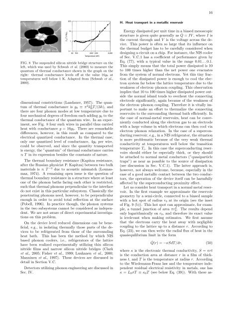
FIG. 8 The suspended silicon nitride bridge structure on the<br />
left, which was used by Schwab et al. (2000) to measure the<br />
quantum of thermal conductance shown <strong>in</strong> the graph on the<br />
right: thermal conductance levels off at the value 16g0 at<br />
temperatures well below 1 K. Adapted from (Schwab et al.,<br />
2000).<br />
dimensional constrictions (L<strong>and</strong>auer, 1957). The quantum<br />
of thermal conductance is g0 ≡ π2k2 BT/(3h), <strong>and</strong><br />
there are four phonon modes at low temperature due to<br />
four mechanical degrees of freedom each add<strong>in</strong>g g0 to the<br />
thermal conductance of the quantum wire. In an experiment,<br />
see Fig. 8 four such wires <strong>in</strong> parallel thus carried<br />
heat with conductance g = 16g0. There are remarkable<br />
differences, however, <strong>in</strong> this result as compared to the<br />
electrical quantized conductance. In the thermal case,<br />
only one quantized level of conductance, 4g0 per wire,<br />
could be observed, <strong>and</strong> s<strong>in</strong>ce the quantity transported<br />
is energy, the ”quantum” of thermal conductance carries<br />
∝ T <strong>in</strong> its expression besides the constants of nature.<br />
The thermal boundary resistance (Kapitza resistance,<br />
after the Russian physicist P. Kapitza) between two bulk<br />
materials is ∝ T −3 due to acoustic mismatch (Lounasmaa,<br />
1974). A rema<strong>in</strong><strong>in</strong>g open issue is the question of<br />
thermal boundary resistance <strong>in</strong> a structure where at least<br />
one of the phonon baths fac<strong>in</strong>g each other is restricted,<br />
such that thermal phonons perpendicular to the <strong>in</strong>terface<br />
do not exist <strong>in</strong> this particular subsystem. Classically the<br />
penetrat<strong>in</strong>g phonons need, however, to be perpendicular<br />
enough <strong>in</strong> order to avoid total reflection at the surface<br />
(Pobell, 1996). In practice though, the phonon systems<br />
<strong>in</strong> the two subsystems cannot be considered as <strong>in</strong>dependent.<br />
We are not aware of direct experimental <strong>in</strong>vestigations<br />
on this problem.<br />
On the device level reduced dimensions can be beneficial,<br />
e.g., <strong>in</strong> isolat<strong>in</strong>g thermally those parts of the devices<br />
to be refrigerated from those of the surround<strong>in</strong>g<br />
heat bath. This has been the method by which NIS<br />
based phonon coolers, i.e., refrigerators of the lattice<br />
have been realized experimentally utiliz<strong>in</strong>g th<strong>in</strong> silicon<br />
nitride films <strong>and</strong> narrow silicon nitride bridges (Clark<br />
et al., 2005; Fisher et al., 1999; Luukanen et al., 2000;<br />
Mann<strong>in</strong>en et al., 1997). These devices are discussed <strong>in</strong><br />
detail <strong>in</strong> Section V.C.<br />
Detectors utiliz<strong>in</strong>g phonon eng<strong>in</strong>eer<strong>in</strong>g are discussed <strong>in</strong><br />
Sec. IV.<br />
H. Heat transport <strong>in</strong> a metallic reservoir<br />
16<br />
Energy dissipated per unit time <strong>in</strong> a biased mesoscopic<br />
structure is given quite generally as ˙ Q = IV , where I is<br />
the current through <strong>and</strong> V is the voltage across the device.<br />
This power is often so large that its <strong>in</strong>fluence on<br />
the thermal budget has to be carefully considered when<br />
design<strong>in</strong>g a circuit on a chip. For <strong>in</strong>stance, the NIS cooler<br />
of Sec. V.C.1 has a coefficient of performance given by<br />
Eq. (77), with a typical value <strong>in</strong> the range 0.01. . . 0.1.<br />
This simply means that the total power dissipated is 10<br />
to 100 times higher than the net power one evacuates<br />
from the system of normal electrons. Yet this t<strong>in</strong>y fraction<br />
of the dissipated power is enough to cool the electron<br />
system far below the lattice temperature due to the<br />
weakness of electron–phonon coupl<strong>in</strong>g. This observation<br />
implies that 10 to 100 times higher dissipated power outside<br />
the normal isl<strong>and</strong> tends to overheat the connect<strong>in</strong>g<br />
electrode significantly, aga<strong>in</strong> because of the weakness of<br />
the electron–phonon coupl<strong>in</strong>g. Therefore it is vitally important<br />
to make an effort to thermalize the connect<strong>in</strong>g<br />
reservoirs to the surround<strong>in</strong>g thermal bath efficiently. In<br />
the case of normal-metal reservoirs, heat can be conveniently<br />
conducted along the electron gas to an electrode<br />
with a large volume <strong>in</strong> which electrons can then cool via<br />
electron–phonon relaxation. In the case of a superconduct<strong>in</strong>g<br />
reservoir, e.g., <strong>in</strong> a NIS refrigerator, the situation<br />
is more problematic because of the very weak thermal<br />
conductivity at temperatures well below the transition<br />
temperature Tc. In this case the superconduct<strong>in</strong>g reservoirs<br />
should either be especially thick, or they should<br />
be attached to normal metal conductors (”quasiparticle<br />
traps”) as near as possible to the source of dissipation<br />
(see discussion <strong>in</strong> Sec. V.C.1). The latter approach is,<br />
however, not always welcome, because, especially <strong>in</strong> the<br />
case of a good metallic contact between the two conductors,<br />
the operation of the device itself can be harmfully<br />
affected by the superconduct<strong>in</strong>g proximity effect.<br />
Let us consider heat transport <strong>in</strong> a normal metal reservoir.<br />
In the first example we approximate the reservoir<br />
geometry by a semi-circle, connected to a biased sample<br />
with a hot spot of radius r0 at its orig<strong>in</strong> (see the <strong>in</strong>set<br />
of Fig. 9 (b)). This hot spot can approximate, for example,<br />
a tunnel junction of area πr 2 0. The results depend<br />
only logarithmically on r0, <strong>and</strong> therefore its exact value<br />
is irrelevant when mak<strong>in</strong>g estimates. We first assume<br />
that the electrons carry the heat away with negligible<br />
coupl<strong>in</strong>g to the lattice up to a distance r. Accord<strong>in</strong>g to<br />
Eq. (23), we can then write the radial flux of heat <strong>in</strong> the<br />
quasiequilibrium limit <strong>in</strong> the form<br />
˙Q(r) = −κSdT/dr, (50)<br />
where κ is the electronic thermal conductivity, S = πrt<br />
is the conduction area at distance r <strong>in</strong> a film of thickness<br />
t, <strong>and</strong> T is the temperature at radius r. Accord<strong>in</strong>g<br />
to the Wiedemann-Franz law <strong>and</strong> the temperature <strong>in</strong>dependent<br />
residual electrical resistivity <strong>in</strong> metals, one has<br />
κ = L0σT ≡ κ0T (see below Eq. (39)). With these as-