Thermal properties in mesoscopics: physics and ... - ResearchGate
Thermal properties in mesoscopics: physics and ... - ResearchGate
Thermal properties in mesoscopics: physics and ... - ResearchGate

You also want an ePaper? Increase the reach of your titles
YUMPU automatically turns print PDFs into web optimized ePapers that Google loves.
tacts may be more preferable than thermometers apply<strong>in</strong>g<br />
tunnel contacts. In an SNS system, one may aga<strong>in</strong><br />
employ either the supercurrent or quasiparticle current as<br />
the thermometer. For a given phase φ between the two<br />
superconductors, the former can be expressed through<br />
(Belzig et al., 1999)<br />
IS(φ) = 1<br />
eRN<br />
∞<br />
0<br />
dEjS(E; φ)(1 − 2f(E)), (56)<br />
where RN is the normal-state resistance of the weak l<strong>in</strong>k,<br />
jS(E; φ) is the spectral supercurrent (Heikkilä et al.,<br />
2002), <strong>and</strong> the energies are measured from the chemical<br />
potential of the superconductors. Hence, the supercurrent<br />
has the form of Eq. (54). In practice, one does<br />
not necessarily measure IS(φ), but the critical current<br />
IC = maxφ IS(φ). In diffusive junctions, this is obta<strong>in</strong>ed<br />
typically for φ near π/2, although the maximum po<strong>in</strong>t<br />
depends slightly on temperature.<br />
The problem <strong>in</strong> SNS thermometry is <strong>in</strong> the fact that<br />
the supercurrent spectrum jS(ε) depends on the quality<br />
of the <strong>in</strong>terface, on the specific geometry of the system,<br />
<strong>and</strong> most importantly, on the distance L between<br />
the two superconductors compared to the superconduct<strong>in</strong>g<br />
coherence length ξ0 = D/(2∆) (Heikkilä et al.,<br />
2002). Therefore, IC(T ) dependence is not universal.<br />
However, the size of the junction can be tuned to meet<br />
the specific temperature range of <strong>in</strong>terest. In the limit of<br />
short junctions, L ξ0 (Kulik <strong>and</strong> Omel’yanchuk, 1978),<br />
the temperature scale for the critical current is given by<br />
the superconduct<strong>in</strong>g energy gap ∆ <strong>and</strong> for kBT ≪ ∆,<br />
the supercurrent depends very weakly on the temperature.<br />
In a typical case ξ0 ∼ 100 . . . 200 nm, <strong>and</strong> thus<br />
already a weak l<strong>in</strong>k with L of the order of 1 µm, easily<br />
realisable by st<strong>and</strong>ard lithography techniques, lies <strong>in</strong><br />
the ”long” limit. There, the critical current is IC =<br />
c(kBT ) 3/2 exp(− √<br />
2πkBT/ET )/(eRN ET ) (Zaik<strong>in</strong> <strong>and</strong><br />
Zharkov, 1981). This equation is valid for kBT 5ET .<br />
Here ET = D/L2 <strong>and</strong> the prefactor c depends on the<br />
geometry (Heikkilä et al., 2002), for example for a twoprobe<br />
configuration c = 64 √ 2π3 /(3 + 2 √ 2). The exponential<br />
temperature dependence <strong>and</strong> the crossover between<br />
the long- <strong>and</strong> short-junction limits were experimentally<br />
<strong>in</strong>vestigated by Dubos et al. (2001) <strong>and</strong> the<br />
above theoretical predictions were confirmed.<br />
Us<strong>in</strong>g a four-probe configuration with SNS junctions of<br />
different lengths, Jiang et al. (2003) exploited the strong<br />
temperature dependence of the supercurrent to measure<br />
the local temperature. The device worked <strong>in</strong> the regime<br />
where part of the junctions were <strong>in</strong> the supercurrentcarry<strong>in</strong>g<br />
state <strong>and</strong> part of them <strong>in</strong> the dissipative state.<br />
In the limit where supercurrent is completely suppressed,<br />
there is still a weaker temperature dependence of the<br />
conductance, due to the proximity-effect correction (c.f.,<br />
Eq. (46)) (Charlat et al., 1996). This can also be used for<br />
thermometry (Aumentado et al., 1999), but due to the<br />
much smaller effect of temperature on the conductance,<br />
it is less sensitive.<br />
Besides be<strong>in</strong>g just a thermometer of the electron gas,<br />
20<br />
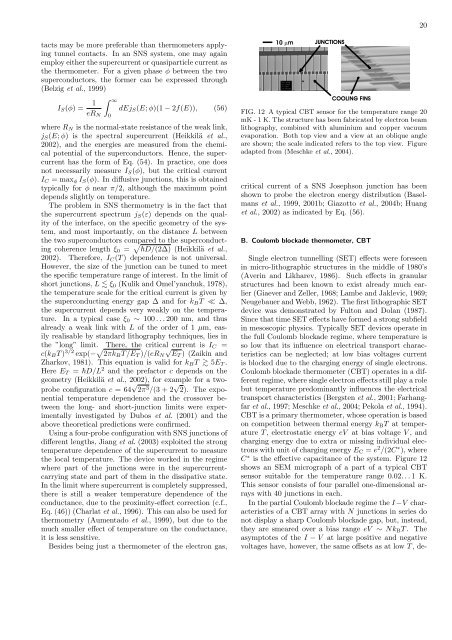
FIG. 12 A typical CBT sensor for the temperature range 20<br />
mK - 1 K. The structure has been fabricated by electron beam<br />
lithography, comb<strong>in</strong>ed with alum<strong>in</strong>ium <strong>and</strong> copper vacuum<br />
evaporation. Both top view <strong>and</strong> a view at an oblique angle<br />
are shown; the scale <strong>in</strong>dicated refers to the top view. Figure<br />
adapted from (Meschke et al., 2004).<br />
critical current of a SNS Josephson junction has been<br />
shown to probe the electron energy distribution (Baselmans<br />
et al., 1999, 2001b; Giazotto et al., 2004b; Huang<br />
et al., 2002) as <strong>in</strong>dicated by Eq. (56).<br />
B. Coulomb blockade thermometer, CBT<br />
S<strong>in</strong>gle electron tunnell<strong>in</strong>g (SET) effects were foreseen<br />
<strong>in</strong> micro-lithographic structures <strong>in</strong> the middle of 1980’s<br />
(Aver<strong>in</strong> <strong>and</strong> Likharev, 1986). Such effects <strong>in</strong> granular<br />
structures had been known to exist already much earlier<br />
(Giaever <strong>and</strong> Zeller, 1968; Lambe <strong>and</strong> Jaklevic, 1969;<br />
Neugebauer <strong>and</strong> Webb, 1962). The first lithographic SET<br />
device was demonstrated by Fulton <strong>and</strong> Dolan (1987).<br />
S<strong>in</strong>ce that time SET effects have formed a strong subfield<br />
<strong>in</strong> mesoscopic <strong>physics</strong>. Typically SET devices operate <strong>in</strong><br />
the full Coulomb blockade regime, where temperature is<br />
so low that its <strong>in</strong>fluence on electrical transport characteristics<br />
can be neglected; at low bias voltages current<br />
is blocked due to the charg<strong>in</strong>g energy of s<strong>in</strong>gle electrons.<br />
Coulomb blockade thermometer (CBT) operates <strong>in</strong> a different<br />
regime, where s<strong>in</strong>gle electron effects still play a role<br />
but temperature predom<strong>in</strong>antly <strong>in</strong>fluences the electrical<br />
transport characteristics (Bergsten et al., 2001; Farhangfar<br />
et al., 1997; Meschke et al., 2004; Pekola et al., 1994).<br />
CBT is a primary thermometer, whose operation is based<br />
on competition between thermal energy kBT at temperature<br />
T , electrostatic energy eV at bias voltage V , <strong>and</strong><br />
charg<strong>in</strong>g energy due to extra or miss<strong>in</strong>g <strong>in</strong>dividual electrons<br />
with unit of charg<strong>in</strong>g energy EC = e 2 /(2C ∗ ), where<br />
C ∗ is the effective capacitance of the system. Figure 12<br />
shows an SEM micrograph of a part of a typical CBT<br />
sensor suitable for the temperature range 0.02. . . 1 K.<br />
This sensor consists of four parallel one-dimensional arrays<br />
with 40 junctions <strong>in</strong> each.<br />
In the partial Coulomb blockade regime the I −V characteristics<br />
of a CBT array with N junctions <strong>in</strong> series do<br />
not display a sharp Coulomb blockade gap, but, <strong>in</strong>stead,<br />
they are smeared over a bias range eV ∼ NkBT . The<br />
asymptotes of the I − V at large positive <strong>and</strong> negative<br />
voltages have, however, the same offsets as at low T , de-