Thermal properties in mesoscopics: physics and ... - ResearchGate
Thermal properties in mesoscopics: physics and ... - ResearchGate
Thermal properties in mesoscopics: physics and ... - ResearchGate

Create successful ePaper yourself
Turn your PDF publications into a flip-book with our unique Google optimized e-Paper software.
e 2 R /Δ T 2 (0)(×10 -2 Q&Q&<br />
)<br />
6<br />
k T/Δ(0) = 0.4<br />
B<br />
3<br />
0<br />
6<br />
-3<br />
3<br />
= 1<br />
0.94<br />
¡ = 1<br />
0.98<br />
0.96<br />
0.96<br />
0.98<br />
(a)<br />
Q& (nW/μm<br />
A<br />
2 )(×10 2 )<br />
-6<br />
0<br />
0.0<br />
-9<br />
0.0<br />
0.94<br />
0.4<br />
kBT/Δ(0) 0.5<br />
0.8<br />
1.0 1.5<br />
eV/Δ(0)<br />
8<br />
7<br />
6<br />
5<br />
4<br />
3<br />
k T/ Δ (0)=0.4<br />
2 B<br />
1<br />
0<br />
¢ = 1<br />
0.98<br />
0.96<br />
0.94<br />
25<br />
20<br />
15<br />
10<br />
5<br />
0.0 0.4 0.8 0<br />
k T/Δ(0)<br />
B<br />
0.3<br />
0.2<br />
0.15<br />
0.94 0.96 0.98 1.00<br />
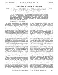
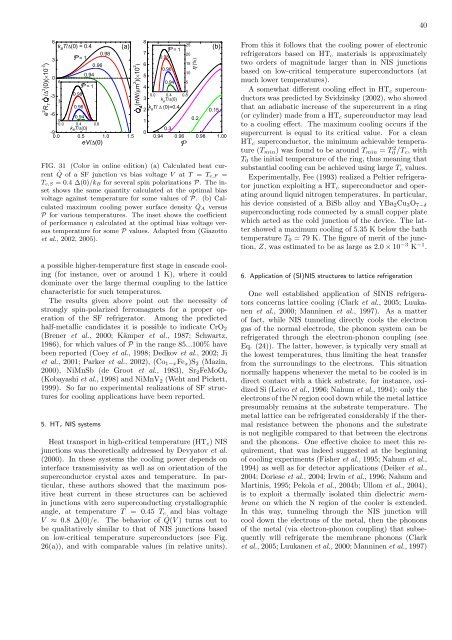
FIG. 31 (Color <strong>in</strong> onl<strong>in</strong>e edition) (a) Calculated heat current<br />
˙ Q of a SF junction vs bias voltage V at T = Te,F =<br />
Te,S = 0.4 ∆(0)/kB for several sp<strong>in</strong> polarizations P. The <strong>in</strong>set<br />
shows the same quantity calculated at the optimal bias<br />
voltage aga<strong>in</strong>st temperature for some values of P. (b) Calculated<br />
maximum cool<strong>in</strong>g power surface density ˙ QA versus<br />
P for various temperatures. The <strong>in</strong>set shows the coefficient<br />
of performance η calculated at the optimal bias voltage versus<br />
temperature for some P values. Adapted from (Giazotto<br />
et al., 2002, 2005).<br />
a possible higher-temperature first stage <strong>in</strong> cascade cool<strong>in</strong>g<br />
(for <strong>in</strong>stance, over or around 1 K), where it could<br />
dom<strong>in</strong>ate over the large thermal coupl<strong>in</strong>g to the lattice<br />
characteristic for such temperatures.<br />
The results given above po<strong>in</strong>t out the necessity of<br />
strongly sp<strong>in</strong>-polarized ferromagnets for a proper operation<br />
of the SF refrigerator. Among the predicted<br />
half-metallic c<strong>and</strong>idates it is possible to <strong>in</strong>dicate CrO2<br />
(Brener et al., 2000; Kämper et al., 1987; Schwartz,<br />
1986), for which values of P <strong>in</strong> the range 85...100% have<br />
been reported (Coey et al., 1998; Dedkov et al., 2002; Ji<br />
et al., 2001; Parker et al., 2002), (Co1−xFex)S2 (Maz<strong>in</strong>,<br />
2000), NiMnSb (de Groot et al., 1983), Sr2FeMoO6<br />
(Kobayashi et al., 1998) <strong>and</strong> NiMnV2 (Weht <strong>and</strong> Pickett,<br />
1999). So far no experimental realizations of SF structures<br />
for cool<strong>in</strong>g applications have been reported.<br />
5. HTc NIS systems<br />
Heat transport <strong>in</strong> high-critical temperature (HTc) NIS<br />
junctions was theoretically addressed by Devyatov et al.<br />
(2000). In these systems the cool<strong>in</strong>g power depends on<br />
<strong>in</strong>terface transmissivity as well as on orientation of the<br />
superconductor crystal axes <strong>and</strong> temperature. In particular,<br />
these authors showed that the maximum positive<br />
heat current <strong>in</strong> these structures can be achieved<br />
<strong>in</strong> junctions with zero superconduct<strong>in</strong>g crystallographic<br />
angle, at temperature T = 0.45 Tc <strong>and</strong> bias voltage<br />
V ≈ 0.8 ∆(0)/e. The behavior of ˙ Q(V ) turns out to<br />
be qualitatively similar to that of NIS junctions based<br />
on low-critical temperature superconductors (see Fig.<br />
26(a)), <strong>and</strong> with comparable values (<strong>in</strong> relative units).<br />
P<br />
η (%)<br />
(b)<br />
40<br />
From this it follows that the cool<strong>in</strong>g power of electronic<br />
refrigerators based on HTc materials is approximately<br />
two orders of magnitude larger than <strong>in</strong> NIS junctions<br />
based on low-critical temperature superconductors (at<br />
much lower temperatures).<br />
A somewhat different cool<strong>in</strong>g effect <strong>in</strong> HTc superconductors<br />
was predicted by Svidz<strong>in</strong>sky (2002), who showed<br />
that an adiabatic <strong>in</strong>crease of the supercurrent <strong>in</strong> a r<strong>in</strong>g<br />
(or cyl<strong>in</strong>der) made from a HTc superconductor may lead<br />
to a cool<strong>in</strong>g effect. The maximum cool<strong>in</strong>g occurs if the<br />
supercurrent is equal to its critical value. For a clean<br />
HTc superconductor, the m<strong>in</strong>imum achievable temperature<br />
(Tm<strong>in</strong>) was found to be around Tm<strong>in</strong> = T 2 0 /Tc, with<br />
T0 the <strong>in</strong>itial temperature of the r<strong>in</strong>g, thus mean<strong>in</strong>g that<br />
substantial cool<strong>in</strong>g can be achieved us<strong>in</strong>g large Tc values.<br />
Experimentally, Fee (1993) realized a Peltier refrigerator<br />
junction exploit<strong>in</strong>g a HTc superconductor <strong>and</strong> operat<strong>in</strong>g<br />
around liquid nitrogen temperatures. In particular,<br />
his device consisted of a BiSb alloy <strong>and</strong> YBa2Cu3O7−δ<br />
superconduct<strong>in</strong>g rods connected by a small copper plate<br />
which acted as the cold junction of the device. The latter<br />
showed a maximum cool<strong>in</strong>g of 5.35 K below the bath<br />
temperature T0 = 79 K. The figure of merit of the junction,<br />
Z, was estimated to be as large as 2.0 × 10 −3 K −1 .<br />
6. Application of (SI)NIS structures to lattice refrigeration<br />
One well established application of SINIS refrigerators<br />
concerns lattice cool<strong>in</strong>g (Clark et al., 2005; Luukanen<br />
et al., 2000; Mann<strong>in</strong>en et al., 1997). As a matter<br />
of fact, while NIS tunnel<strong>in</strong>g directly cools the electron<br />
gas of the normal electrode, the phonon system can be<br />
refrigerated through the electron-phonon coupl<strong>in</strong>g (see<br />
Eq. (24)). The latter, however, is typically very small at<br />
the lowest temperatures, thus limit<strong>in</strong>g the heat transfer<br />
from the surround<strong>in</strong>gs to the electrons. This situation<br />
normally happens whenever the metal to be cooled is <strong>in</strong><br />
direct contact with a thick substrate, for <strong>in</strong>stance, oxidized<br />
Si (Leivo et al., 1996; Nahum et al., 1994): only the<br />
electrons of the N region cool down while the metal lattice<br />
presumably rema<strong>in</strong>s at the substrate temperature. The<br />
metal lattice can be refrigerated considerably if the thermal<br />
resistance between the phonons <strong>and</strong> the substrate<br />
is not negligible compared to that between the electrons<br />
<strong>and</strong> the phonons. One effective choice to meet this requirement,<br />
that was <strong>in</strong>deed suggested at the beg<strong>in</strong>n<strong>in</strong>g<br />
of cool<strong>in</strong>g experiments (Fisher et al., 1995; Nahum et al.,<br />
1994) as well as for detector applications (Deiker et al.,<br />
2004; Doriese et al., 2004; Irw<strong>in</strong> et al., 1996; Nahum <strong>and</strong><br />
Mart<strong>in</strong>is, 1995; Pekola et al., 2004b; Ullom et al., 2004),<br />
is to exploit a thermally isolated th<strong>in</strong> dielectric membrane<br />
on which the N region of the cooler is extended.<br />
In this way, tunnel<strong>in</strong>g through the NIS junction will<br />
cool down the electrons of the metal, then the phonons<br />
of the metal (via electron-phonon coupl<strong>in</strong>g) that subsequently<br />
will refrigerate the membrane phonons (Clark<br />
et al., 2005; Luukanen et al., 2000; Mann<strong>in</strong>en et al., 1997)