Installation & Operation Manual - StellarSupport - John Deere
Installation & Operation Manual - StellarSupport - John Deere
Installation & Operation Manual - StellarSupport - John Deere

Create successful ePaper yourself
Turn your PDF publications into a flip-book with our unique Google optimized e-Paper software.
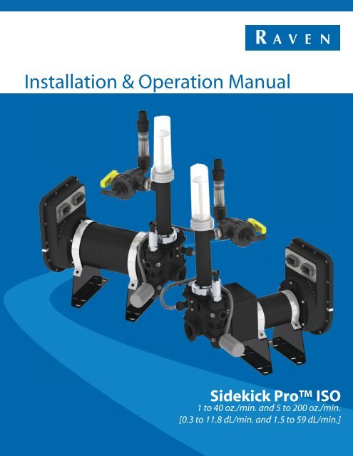
<strong>Installation</strong> & <strong>Operation</strong> <strong>Manual</strong><br />
Sidekick Pro ISO<br />
1 to 40 oz./min. and 5 to 200 oz./min.<br />
[0.3 to 11.8 dL/min. and 1.5 to 59 dL/min.]
Disclaimer<br />
While every effort has been made to ensure the accuracy of this document,<br />
Raven Industries assumes no responsibility for omissions and errors. Nor is any<br />
liability assumed for damages resulting from the use of information contained<br />
herein.<br />
Raven Industries shall not be responsible or liable for incidental or consequential<br />
damages or a loss of anticipated benefits or profits, work stoppage or loss, or<br />
impairment of data arising out of the use, or inability to use, this system or any of<br />
its components. Raven Industries shall not be held responsible for any<br />
modifications or repairs made outside our facilities, nor damages resulting from<br />
inadequate maintenance of this system.<br />
As with all wireless and satellite signals, several factors may affect the availability<br />
and accuracy of wireless and satellite navigation and correction services (e.g.<br />
GPS, GNSS, SBAS, etc.). Therefore, Raven Industries cannot guarantee the<br />
accuracy, integrity, continuity, or availability of these services and cannot<br />
guarantee the ability to use Raven systems, or products used as components of<br />
systems, which rely upon the reception of these signals or availability of these<br />
services. Raven Industries accepts no responsibility for the use of any of these<br />
signals or services for other than the stated purpose.<br />
©Raven Industries, Inc. 2011, 2012
Table of Contents<br />
Chapter 1 Important Safety Information................................................. 1<br />
Chemical Handling and Safety ............................................................................................ 2<br />
Electrical Safety ................................................................................................................... 2<br />
Chapter 2 Introduction............................................................................. 3<br />
System Overview ...................................................................................................................... 3<br />
Injection System Components ............................................................................................. 3<br />
Sidekick Pro ISO Features .................................................................................................... 4<br />
Closed Calibration System .................................................................................................. 4<br />
Fast Rate Response ............................................................................................................ 5<br />
Integrated Motor Control Node ............................................................................................ 5<br />
System Diagnostics ............................................................................................................. 6<br />
Sidekick Pro ISO Pump Specifications .................................................................................. 6<br />
Updates ..................................................................................................................................... 9<br />
Chapter 3 <strong>Installation</strong>............................................................................. 11<br />
Overview ................................................................................................................................. 11<br />
Initial Plumbing and Point of Injection ..................................................................................... 12<br />
Mount the Sidekick Pro ISO Pump<br />
and Chemical Tank .................................................................................................................. 16<br />
Mount the Injection Module ............................................................................................... 16<br />
Mount the Chemical Tank .................................................................................................. 17<br />
Mount the Sidekick Pro ISO Pump ................................................................................ 17<br />
Sidekick Pro ISO Injection System Plumbing ...................................................................... 19<br />
Plumb the Sidekick Pro ISO Pump ................................................................................ 19<br />
Plumb the Sidekick Pro ISO Closed Calibration System ............................................... 20<br />
Plumb the Recommended Pump Rinse System ............................................................... 21<br />
ISOBUS and Power Connections ........................................................................................... 23<br />
Best <strong>Installation</strong> Practices ................................................................................................. 23<br />
Sidekick Pro ISO CANbus Connection .......................................................................... 26<br />
Verify <strong>Installation</strong> of the Sidekick Pro ISO ........................................................................... 27<br />
Chapter 4 Calibration............................................................................. 29<br />
Detecting and Addressing the Motor Control Node ................................................................. 29<br />
Virtual Terminal Calibration .................................................................................................... 31<br />
Product Home Screen Calibration Settings ....................................................................... 32<br />
Product Setup Screen Calibration Settings ....................................................................... 34<br />
Alarms Setup Screen Calibration Settings ........................................................................ 37<br />
Chapter 5 <strong>Operation</strong>............................................................................... 41<br />
Sidekick Pro ISO Priming and Calibration ........................................................................... 41<br />
<strong>Manual</strong> No. 016-0171-509 i
Table of Contents<br />
Verify Control Console Settings ......................................................................................... 41<br />
Prime the Injection Pump .................................................................................................. 41<br />
Calibrate the Injection Pump ............................................................................................. 43<br />
Application Modes and Pump <strong>Operation</strong> ................................................................................. 45<br />
Application Modes ............................................................................................................. 45<br />
Setting the Pump for Field <strong>Operation</strong> ................................................................................ 45<br />
Sidekick Pro ISO <strong>Operation</strong> ........................................................................................... 46<br />
Product Totals Screen ............................................................................................................. 48<br />
Field Tallies Area ............................................................................................................... 49<br />
Total Tallies Area ............................................................................................................... 49<br />
Area per Hour and Flow Rate Display ............................................................................... 50<br />
Chapter 6 Injection Diagnostics and Troubleshooting....................... 51<br />
Product Diagnostics Screen .................................................................................................... 51<br />
Pump Status ...................................................................................................................... 52<br />
Run Time Data ................................................................................................................... 52<br />
Product Information Screen ..................................................................................................... 53<br />
Motor Control Node LED Status Indicators ............................................................................. 55<br />
Alarms ............................................................................................................................... 55<br />
Chapter 7 System Maintenance ............................................................ 59<br />
Maintenance and Cleaning ...................................................................................................... 59<br />
Check Valve O-Rings ........................................................................................................ 60<br />
Pump Cam and Bearing .................................................................................................... 62<br />
Piston Seal Replacement .................................................................................................. 62<br />
Seasonal Maintenance and Storage ....................................................................................... 64<br />
Chapter 8 Replacement Parts ............................................................... 67<br />
Sidekick Pro ISO Pump Replacement Parts ........................................................................ 67<br />
Injection Pump Pressure Transducer ................................................................................ 68<br />
Injection Pump Vacuum Switch ......................................................................................... 69<br />
Injection Pump Flow Monitor Sensor ................................................................................. 69<br />
Injection Pump Encoder ....................................................................................................71<br />
Check Valve Assemblies ................................................................................................... 73<br />
Sidekick Pro ISO 1 to 40 oz./min. Pump ........................................................................ 74<br />
Sidekick Pro ISO 5 to 200 oz./min. Pump ...................................................................... 77<br />
Modules with 24 Gallon Tank and 1 to 40 oz./min. Pump .................................................. 80<br />
Modules with 24 Gallon Tank and 5 to 200 oz./min. Pump ................................................ 84<br />
ii ISO Sidekick Pro <strong>Installation</strong> & <strong>Operation</strong> <strong>Manual</strong>
CHAPTER<br />
1<br />
Chapt er 1Important Safety<br />
Information<br />
Read this manual carefully before installing the Sidekick Pro ISO direct injection module or any other system<br />
components.<br />
• Follow all safety information presented within this manual.<br />
• Keep safety labels in good condition. Replace missing or damaged safety labels as necessary and verify<br />
labels are included on replacement parts or new equipment components. Replacement safety labels are<br />
available from any local Raven dealer.<br />
• If you require assistance with any portion of the installation or service of the direct injection equipment,<br />
contact a local Raven dealer for support.<br />
When operating the machine after installing the Sidekick Pro ISO, observe the following safety measures:<br />
• Be alert and aware of surroundings.<br />
NOTICE<br />
• Do not operate any agricultural equipment while under the influence of alcohol or an illegal substance.<br />
• Determine and remain a safe working distance from obstacles or other individuals. The equipment operator<br />
is responsible for disabling the system when a safe working distance has diminished.<br />
Review the operation and safety instructions included with the implement and/or controller.<br />
<strong>Manual</strong> No. 016-0171-509 Rev. B 1
Chapter 1<br />
Chemical Handling and Safety<br />
Chemicals used in agricultural applications may be harmful to your health or the environment if not used<br />
responsibly. Review the safe, effective, and legal use and disposal of agricultural chemicals with a chemical<br />
supplier.<br />
• Always follow safety labels and instructions provided by the chemical manufacturer or supplier.<br />
• Store agricultural chemicals in original containers and do not transfer to unmarked containers or containers<br />
used for food or drink. Store chemicals in a secure, locked area away from human or livestock food and<br />
keep children away from storage areas.<br />
• Avoid inhaling chemical dust or spray particulate and avoid direct contact with agricultural chemicals.<br />
Always wear appropriate personal protective equipment as recommended by the chemical and/or<br />
equipment manufacturer. Wash hands and face after using agricultural chemicals and before eating,<br />
drinking, or using the rest room.<br />
• Seek medical attention immediately if illness occurs during or shortly after the use of chemicals.<br />
• Fill, flush, calibrate, and decontaminate sprayer systems in an area where runoff will not reach ponds,<br />
lakes/streams, livestock areas, gardens, or populated areas. Thoroughly flush or rinse equipment used to<br />
mix, transfer, and apply chemicals after use.<br />
• Before servicing any component of the system, thoroughly flush or rinse components with water.<br />
• Improper disposal of waste may threaten the environment and ecology. Dispose of empty containers<br />
properly. Triple-rinse empty containers and puncture or crush when disposing. Contact a local<br />
environmental or recycling center for additional information.<br />
If the system malfunctions or becomes clogged, stop the engine or pump and relieve pressure from the<br />
spraying system before servicing.<br />
Do not operate machinery without instruction and keep equipment in proper working condition. Unauthorized<br />
modification to equipment may impair machine function and/or safety and may shorten the working life of<br />
equipment.<br />
Wear clothing appropriate for the job being performed and avoid loose fitting clothing while working on or near<br />
moving components. Keep long hair away from moving components.<br />
Electrical Safety<br />
WARNING<br />
CAUTION<br />
Do not reverse power leads. Doing so could cause severe damage to the equipment. Always make sure that<br />
the power leads are connected to the correct polarity as marked. Ensure that the power cables are the last<br />
cables to be connected.<br />
Remove rings and other jewelry to prevent electrical shorts or entanglement in moving parts.<br />
2 Sidekick Pro ISO <strong>Installation</strong> & <strong>Operation</strong> <strong>Manual</strong>
CHAPTER<br />
2<br />
System Overview<br />
Chapt er 2Introduction<br />
The Raven Sidekick Pro ISO injection system is designed to provide efficient and accurate application of<br />
liquid chemicals applied from an injection module. Using a separate injection module, or tank, eliminates<br />
mixing chemicals and reduces chemical waste, and simplifies equipment care and maintenance.<br />
Sidekick Pro ISO provides connectivity to a ISOBUS system to allow an existing ISO virtual terminal (VT)<br />
display to control the rate of the chemical injection system.<br />
After proper installation and calibration of the injection system and a VT display, including a target rate for the<br />
carrier and injected chemicals, the operator enables the product control system and the control console will<br />
automatically maintain the flow regardless of vehicle speed or active boom sections.<br />
Performance of the ISOBUS injection system relies upon proper installation and maintenance of the complete<br />
sprayer system. Please review this manual before installing or operating this system to help ensure proper<br />
setup and follow instructions provided for proper care and maintenance of the injection system.<br />
Note: The Raven Sidekick Pro ISO injection systems are not compatible with <strong>John</strong> <strong>Deere</strong> Spray<br />
Ready application equipment.<br />
Injection System Components<br />
The direct injection system consists of:<br />
• ISOBUS based virtual terminal (VT) display (not provided)<br />
• Appropriate cabling and plumbing<br />
• Sidekick Pro ISO injection pump<br />
• In-line mixer<br />
• Cabling required to connect the injection system components and existing ISOBUS<br />
• Check valves<br />
• Raven ISOBUS product control node for carrier rate control and to relay section status to the Sidekick Pro<br />
ISO node.<br />
<strong>Manual</strong> No. 016-0171-509 Rev. B 3
Chapter 2<br />
Sidekick Pro ISO Features<br />
Closed Calibration System<br />
Calibrating chemical injection pumps is necessary for accurate chemical injection applications. The Sidekick<br />
Pro ISO closed calibration system allows the operator to perform calibration or system tests without catching or<br />
handling dangerous chemicals.<br />
Priming<br />
An automatic priming feature ensures the pump is correctly primed and ready for operation when the operator<br />
is ready to apply product.<br />
Pump Calibrator<br />
The pump calibrator provides a quick tool to check pump efficiency and verify that the pump is ready for<br />
operation.<br />
FIGURE 1. Pump Calibrator<br />
4 Sidekick Pro ISO <strong>Installation</strong> & <strong>Operation</strong> <strong>Manual</strong>
Fast Rate Response<br />
Introduction<br />
High precision sensing allows the Sidekick Pro ISO direct injection pump to dynamically lock onto the target<br />
rate while the application equipment works the field. This ensures that the injection pump is providing the<br />
proper chemical concentration throughout the field regardless of vehicle speed or boom section status<br />
changes.<br />
Integrated Motor Control Node<br />
Sidekick Pro ISO features an integrated motor control node mounted directly on the pump housing for<br />
simplified installation and enhanced performance. The control node features status LEDs which provide status<br />
and CAN communication information which the operator may be able to use during calibration or system<br />
troubleshooting.<br />
Integrated Calibration Switch<br />
The integrated motor control node also features a sealed calibration switch. The sealed calibration switch<br />
allows the operator to begin the pump calibration process by passing a metallic object, such as a screwdriver,<br />
across the switch sensor on the Sidekick Pro ISO injection pump. This feature allows the operator to run<br />
multiple calibration tests quickly and easily and ensure the system is ready for operation.<br />
Note: Calibration must be initiated from the control console in the vehicle cab. See the Calibrate the<br />
Injection Pump section on page 43 for a detailed calibration procedure.<br />
The calibration status LED light will flash when the calibration sensor registers a metallic object by the switch.<br />
Pass the metal object past the sensor to initiate a pump calibration.<br />
FIGURE 2. Motor Control Node Calibration Sensor<br />
Calibration<br />
Status LED<br />
Calibration<br />
Sensor Location<br />
<strong>Manual</strong> No. 016-0171-509 Rev. B 5<br />
2
Chapter 2<br />
System Diagnostics<br />
Enhanced diagnostic features are monitored by the control console during operation of the Sidekick Pro ISO<br />
injection system to help identify potential issues and minimize equipment down time. Refer to Chapter 6,<br />
Injection Diagnostics and Troubleshooting for more information on using diagnostics features on a specific<br />
console.<br />
Flow Monitoring<br />
The CAN integrated Sidekick Pro ISO offers enhanced monitoring of pump operation during chemical injection<br />
applications to alert the operator to conditions such as an empty chemical supply tank, low injection pressure,<br />
incorrect meter calibration, or issues with the injection pump valves.<br />
Sidekick Pro ISO Pump Specifications<br />
The Sidekick Pro ISO injection pump is a positive displacement, variable speed piston pump used for direct<br />
chemical injection applications.<br />
Dimensions<br />
Pistons<br />
Maximum Stroke Length<br />
Flow Output Range<br />
Maximum Operating Pressure<br />
Maximum Power Required<br />
Maximum Recommended<br />
Suction Lift<br />
Inlet and Outlet Plumbing<br />
Wetted Parts<br />
Body Material<br />
Wetted Seals/O-Rings<br />
(See Figure 3 on page 7 or Figure 4 on page 8)<br />
P/N 063-0173-402<br />
5-200 oz./min.<br />
[1.5-59 dl/min.]<br />
1 @ 0.750” Dia.<br />
0.390”<br />
150 PSI<br />
1/4 HP<br />
P/N 063-0173-403<br />
1-40 oz./min.<br />
[0.3-11.8 dl/min.]<br />
6 Sidekick Pro ISO <strong>Installation</strong> & <strong>Operation</strong> <strong>Manual</strong><br />
2 ft.<br />
Mates with Banjo M100 Flange and 3/4” Female NPT<br />
Polypropylene Stainless Steel<br />
Polypropylene<br />
V965-80 Viton and Graphite Filled Teflon
FIGURE 3. Sidekick Pro ISO Injection Pump Dimensions<br />
Note: 5-200 oz./min. pump shown. Basic dimensions are the same for 1-40 oz./min. pump.<br />
Introduction<br />
<strong>Manual</strong> No. 016-0171-509 Rev. B 7<br />
2
Chapter 2<br />
FIGURE 4. Sidekick Pro ISO Injection Pump Dimensions (Cont.)<br />
Note: 5-200 oz./min. pump shown. Overall length of 1-40 oz./min. pump is 13.25 inches [33.66 cm].<br />
8 Sidekick Pro ISO <strong>Installation</strong> & <strong>Operation</strong> <strong>Manual</strong>
Updates<br />
Introduction<br />
Updates for Raven manuals as well as several system components are available at the Applied Technology<br />
Division web site:<br />
www.ravenhelp.com<br />
Sign up for e-mail alerts to receive notice when updates for your Raven products are available on the Raven<br />
web site.<br />
At Raven Industries, we strive to make your experience with our products as rewarding as<br />
possible. One way to improve this experience is to provide us with feedback on this manual.<br />
Your feedback will help shape the future of our product documentation and the overall service<br />
we provide. We appreciate the opportunity to see ourselves as our customers see us and are<br />
eager to gather ideas on how we have been helping or how we can do better.<br />
To serve you best, please send an email with the following information to<br />
techwriting@ravenind.com<br />
-Sidekick Pro ISO <strong>Installation</strong> & <strong>Operation</strong> <strong>Manual</strong><br />
-<strong>Manual</strong> No. 016-0171-509 Rev. B<br />
-Any comments or feedback (include chapter or page numbers if applicable).<br />
-Let us know how long have you been using this or other Raven products.<br />
We will not share your email or any information you provide with anyone else. Your feedback<br />
is valued and extremely important to us.<br />
Thank you for your time.<br />
<strong>Manual</strong> No. 016-0171-509 Rev. B 9<br />
2
Chapter 2<br />
10 Sidekick Pro ISO <strong>Installation</strong> & <strong>Operation</strong> <strong>Manual</strong>
CHAPTER<br />
3<br />
Overview<br />
Chapt er 3<strong>Installation</strong><br />
The following steps must be completed to install a Sidekick Pro ISO injection system:<br />
1. Select and plumb the point of injection. See page 12.<br />
a. Install carrier and chemical injection check valves.<br />
b. Install in-line mixer.<br />
2. Mount the Sidekick Pro ISO injection module or tank. See page 17.<br />
3. Mount the Sidekick Pro ISO injection pump. See page 17.<br />
4. Plumb the Sidekick Pro ISO pump and injection lines into the main carrier line at point of injection. See<br />
page 19.<br />
5. Install the closed calibration system. See page 20.<br />
6. Plumb the recommended rinse system. See page 21.<br />
7. Connect the Sidekick Pro ISO injection pump to CANbus. See page 23.<br />
8. Connect the Sidekick Pro ISO pump to source of electrical power. See page 23.<br />
The following sections provide detailed information and procedure to assist with completing the above steps.<br />
Contact a local Raven dealer for assistance or questions during the installation procedure.<br />
FIGURE 1. Example Sidekick Pro ISO Injection System<br />
<strong>Manual</strong> No. 016-0171-509 Rev. B 11
Chapter 3<br />
Initial Plumbing and Point of Injection<br />
The Raven Sidekick Pro ISO injection system pumps chemical into the main carrier line at the point of<br />
injection. This point must be on the pressure side of the carrier product pump and should be as close to the<br />
boom section valves as possible.<br />
Note: It is not necessary for injected products or chemicals to be measured by the flow meter.<br />
Depending upon the type of applications or chemical mixtures the injection system will normally be<br />
used with, it may be more desirable to place the injection point after the flow meter. This<br />
configuration will minimize the exposure of the flow meter to corrosive chemicals and may extend<br />
the life of the flow meter.<br />
FIGURE 2. Basic Sprayer Plumbing Diagram with Added Injection System<br />
12 Sidekick Pro ISO <strong>Installation</strong> & <strong>Operation</strong> <strong>Manual</strong>
FIGURE 3. Point of Injection Detail<br />
From carrier<br />
product tank<br />
<strong>Installation</strong><br />
Check valves are used in both the carrier and injection lines to prevent back flow and contamination of carrier<br />
and chemical reservoirs. An in-line mixer should be installed after the point of injection to ensure even mixing<br />
of the injected product.<br />
Once a point of injection has been selected:<br />
From injection<br />
module<br />
To boom valve<br />
manifold<br />
1. Install a carrier check valve in the main product line to prevent back flow to the carrier reservoir. Use<br />
Table 1, “Check Valve Sizing and Selection Chart,” on page 14 to determine proper sizing of the carrier<br />
check valve.<br />
2. Install a tee type fitting suitable for chemical applications after the carrier check valve.<br />
3. Install an in-line mixer to the through port of the tee fitting and connect to the existing carrier product line or<br />
boom valve manifold. Use Table 2, “In-line Mixer Sizing and Selection Chart,” on page 15 to determine<br />
proper sizing of the in-line mixer.<br />
4. Install a chemical injection check valve to the injection line in front of the point of injection to prevent back<br />
flow to the chemical reservoir. Use Table 1, “Check Valve Sizing and Selection Chart,” on page 14 to<br />
determine proper sizing of the carrier check valve.<br />
<strong>Manual</strong> No. 016-0171-509 Rev. B 13<br />
3
Chapter 3<br />
FIGURE 4. Check Valves and In-Line Mixer<br />
Port A<br />
Port A<br />
Carrier Check Valve<br />
Recirculation/Priming<br />
Check Valve<br />
Note: Be sure to install the check valves with the flow direction indicator pointing in the direction of<br />
chemical flow.<br />
TABLE 1. Check Valve Sizing and Selection Chart<br />
Recirculation and<br />
Priming Check<br />
Valve a<br />
Injection Point<br />
Check valve 12 PSI<br />
[82.74 kPa]<br />
Carrier Check Valve<br />
Port B<br />
Port B<br />
Raven Part No. “A” NPT “B” NPT<br />
333-0011-100 1/2” (F) 1/2” (M)<br />
333-0011-102 1/2” (F) 1/2” (M)<br />
333-0011-090 1” 1”<br />
333-0011-091 1-1/4” 1-1/4”<br />
333-0011-093 2” 2”<br />
333-0011-094 3” 3”<br />
333-0011-095 4” 4”<br />
a. Check valve features a 0.046” hole necessary for bleeding during<br />
priming procedures.<br />
14 Sidekick Pro ISO <strong>Installation</strong> & <strong>Operation</strong> <strong>Manual</strong><br />
Port A<br />
Port A<br />
Injection Point<br />
Check Valve<br />
Stainless Steal Mixer<br />
Assembly<br />
Port B<br />
Port B
TABLE 2. In-line Mixer Sizing and Selection Chart<br />
FIGURE 5. Pressure Drop vs. Flow Rate<br />
Pressure Drop<br />
(PSI [kPa]<br />
Raven Part No. “A” NPT “B” NPT<br />
063-0171-303 1” 1”<br />
Polypropylene 063-0159-632 1-1/4” 1-1/4”<br />
063-0171-300 2” 2”<br />
Stainless Steel 333-9000-010 3” 3”<br />
Cast Iron 063-0171-784 1” 1”<br />
Stainless Steel Mixer<br />
Assembly a<br />
063-0173-264 4” 4”<br />
a. 3” Check Valve and 3” Banjo Flange included in assembly.<br />
Flow Rate<br />
Gal./min. [L/min.]<br />
2” Check Valve and 2” Mixer<br />
<strong>Installation</strong><br />
3” Check Valve and 3” Mixer<br />
3” Check Valve and 4” Mixer<br />
<strong>Manual</strong> No. 016-0171-509 Rev. B 15<br />
3
Chapter 3<br />
Mount the Sidekick Pro ISO Pump<br />
and Chemical Tank<br />
<strong>Installation</strong> and mounting of the Sidekick Pro ISO injection pump and injection module, or chemical tank, will<br />
vary between implements. Use the following sections to help select an appropriate mounting location on the<br />
implement.<br />
Mount the Injection Module<br />
The Raven Sidekick Pro ISO injection module provides a platform for mounting the chemical supply tank and<br />
Sidekick Pro ISO injection pump in the optimal configuration for pump operation.<br />
Note: The Raven Sidekick Pro ISO injection module may be ordered with a 24 gallon chemical supply<br />
tank or without a chemical tank to connect the injection system with an existing tank on the vehicle<br />
or purchased separately.<br />
FIGURE 6. Injection Module Platform Dimensions<br />
• Mount the injection module platform in an area close to the boom valve manifold. This minimizes the volume<br />
of chemical in the injection line between the pump and point of injection and allows for more accurate<br />
control of the injected chemical.<br />
• Verify that the hand valves and drain are accessible in the selected mounting location.<br />
• Verify that the injection pump is accessible to perform periodic maintenance.<br />
16 Sidekick Pro ISO <strong>Installation</strong> & <strong>Operation</strong> <strong>Manual</strong>
Mount the Chemical Tank<br />
<strong>Installation</strong><br />
• Mount the chemical tank as close as possible to the injection pump. Minimize the length of the product line<br />
between the chemical tank and injection pump. Avoid any product lines longer than 5 ft. [1.5 m] between the<br />
chemical tank and injection pump inlet port.<br />
Note: Long product lines between the chemical tank and injection pump may cause high vacuum<br />
pressures on the pump inlet, long pump priming times or difficulty priming the pump, and larger<br />
amounts of chemical waist during rinsing.<br />
If vacuum errors are encountered during pump operation, one or both of the following corrective<br />
measures may be necessary to reduce inlet pressure:<br />
• Reduce the inlet plumbing length<br />
• Increase the tubing size<br />
• Mount the Sidekick Pro ISO pump so that the line between the injection pump and chemical supply tank is<br />
near level with a slight incline to help relieve air bubbles. The line connected to the pump inlet must not<br />
raise chemical above 2 ft. [0.6 m] from the chemical supply tank outlet. See Figure 9 on page 22.<br />
Mount the Sidekick Pro ISO Pump<br />
• Mount the Sidekick Pro ISO pump as close as possible to the selected point of injection.<br />
• Mount the Sidekick Pro ISO pump so that the outlet port is pointing up. The pump will not meter product<br />
application correctly if the pump is mounted in any other orientation.<br />
• The Sidekick Pro ISO should be mounted in a location which provides access to the pump and control node<br />
to simplify calibration and troubleshooting.<br />
<strong>Manual</strong> No. 016-0171-509 Rev. B 17<br />
3
Chapter 3<br />
FIGURE 7. Sidekick Pro ISO Pump Mounting and Bracket Orientation<br />
Pump Mounting<br />
Bracket<br />
Pump<br />
Outlet<br />
Note: The pump mounting bracket may be rotated to accommodate mounting to a vertical surface,<br />
however, the injection pump must be mounted level with the outlet port perpendicular to the<br />
ground.<br />
18 Sidekick Pro ISO <strong>Installation</strong> & <strong>Operation</strong> <strong>Manual</strong><br />
Pump<br />
Inlet
FIGURE 8. Sidekick Pro ISO Pump Mounting Bracket Bolt Pattern<br />
Sidekick Pro ISO Injection System<br />
Plumbing<br />
Plumb the Sidekick Pro ISO Pump<br />
Pump Inlet<br />
<strong>Installation</strong><br />
Use 3/4” chemically resistant hose between the chemical tank and injection pump inlet. Do not use hose or<br />
tubing that may collapse when a vacuum is applied during pump operation.<br />
The product line should be as straight as possible. Avoid low spots in plumbing to ease pump priming and<br />
avoid chemical waist.<br />
Strainer<br />
A strainer with a #20 mesh screen must be installed on the inlet side of the injection pump.<br />
<strong>Manual</strong> No. 016-0171-509 Rev. B 19<br />
3
Chapter 3<br />
Pump Outlet<br />
Connect the pump outlet to the injection check valve at the point of injection. Use the following hose sizes<br />
depending upon the capacity of the injection pump used with the system.<br />
Avoid product lines longer than 15 ft. [4.5 m] between the pump outlet and the point of injection. Long runs can<br />
cause increased pressure in the pump heads which cause the pump to pull more electrical current and may<br />
raise the temperature of the injection pump motor and integrated motor control node. See Chapter 6, Injection<br />
Diagnostics and Troubleshooting, for details on injection system diagnostics and to monitor pump pressure and<br />
node temperature.<br />
Plumb the Sidekick Pro ISO Closed Calibration System<br />
The Sidekick Pro ISO closed calibration system provides an environmentally effective method of calibrating<br />
the injection pump without exposing the operator to dangerous or hazardous chemicals.<br />
Pump Calibrator<br />
To provide accurate calibration of the injection pump, the pump calibrator (P/N 063-0172-822) must be<br />
installed directly onto the outlet of the pump. This configuration prevents air from getting trapped between the<br />
injection pump and the calibration plunger. Trapped air will cause the plunger to feel “spongy” when pressed<br />
and will cause the pump calibrator to work improperly.<br />
3-Way Valve<br />
A 3-way valve must be plumbed after the closed calibration system to allow chemical to be directed either back<br />
to the chemical tank or to the point of injection.<br />
Hoses<br />
Pump Capacity Tubing Size<br />
1-40 oz./min. 3/8”<br />
5-200 oz./min. 1/2”<br />
CAUTION<br />
Hoses used on the outlet of the injection pump<br />
must be re-enforced, chemically resistant hose<br />
rated for at least 150 PSI at 100° F [1034 kPa at<br />
66° C].<br />
Use chemically resistant hose compatible with the chemicals which will be used with the injection system.<br />
Follow the same hose specifications as described in the Pump Outlet section on page 20 with the closed<br />
calibration system.<br />
20 Sidekick Pro ISO <strong>Installation</strong> & <strong>Operation</strong> <strong>Manual</strong>
Recirculation Check Valve<br />
<strong>Installation</strong><br />
A recirculation and priming check valve (P/N 333-0011-100) must be plumbed into the recirculation line<br />
between the 3-way valve on the outlet side of the injection pump and the chemical tank. This check valve is<br />
required to allow air to bleed off during priming of the injection pump. The recirculation and priming check valve<br />
is also necessary to allow the system to detect if the pump is primed. See Figure 1 on page 11.<br />
Note: The recirculation check valve has a 0.046” dia. hole in the poppet to allow air to pass. This check<br />
valve applies 12 PSI [83.74 kPa] to the pump during priming.<br />
Plumb the Recommended Pump Rinse System<br />
An injection pump rinse system is recommended to enhance the performance of the Sidekick Pro ISO<br />
injection pump and provide a clean method for changing between chemicals. The rinse system flushes<br />
chemical build up or residues which may collect in the injection pump.<br />
Note: Some components of the recommended rinse system may not be available from Raven. The<br />
following components may be purchased separately and plumbed as shown in Figure 9 on<br />
page 22.<br />
• Clean water supply tank<br />
• Strainer (80 Mesh)<br />
• 1/2 PSI check valve (P/N 333-0011-087)<br />
• Appropriate hose or tubing<br />
• Miscellaneous fittings<br />
<strong>Manual</strong> No. 016-0171-509 Rev. B 21<br />
3
Chapter 3<br />
FIGURE 9. Recommended Injection System Plumbing with Optional Pump Rinse Tank<br />
22 Sidekick Pro ISO <strong>Installation</strong> & <strong>Operation</strong> <strong>Manual</strong>
ISOBUS and Power Connections<br />
<strong>Installation</strong><br />
The Sidekick Pro ISO connects to an ISOBUS system via a CAN motor control cable and requires both a<br />
clean logic power and a high current power connection.<br />
Note: Refer to the installation manual for the specific VT display console for detailed information about<br />
installing and powering a CAN system.<br />
Best <strong>Installation</strong> Practices<br />
The information below illustrates proper methods for wiring an ISOBUS system. The main points of ISOBUS<br />
system installation are summarized below.<br />
Note: Following these recommendations will result in the most robust system possible while greatly<br />
reducing CAN communication problems.<br />
1. Always use sealed connectors with dielectric grease. Avoid unsealed, crimped connections (i.e. butt<br />
connectors).<br />
In addition to using dielectric grease, mount all CAN terminators (P/N 063-0172-964) with the connector<br />
pointing down to avoid collecting water and/or chemical. Liquids collecting within the terminator can corrode<br />
pins and may cause CAN communication issues.<br />
2. Connect the power directly to a controlled clean power source.<br />
3. Connect the ground directly to the vehicle’s battery.<br />
4. Node logic power should be connected to a clean power bus relay.<br />
5. Use dedicated bus bars to connect the console and all nodes to the same source for both power and<br />
ground.<br />
6. Provide relays to switch power on and off to avoid draining the battery. Raven recommends connecting the<br />
console to a clean power source (at relay) and using the vehicle ignition switch to switch the relay.<br />
CAN Terminators<br />
A CAN terminator (P/N 063-0172-964) is required to provide optimal signal integrity through the CANbus. This<br />
terminator should be installed as shown in Figure 10 on page 24.<br />
<strong>Manual</strong> No. 016-0171-509 Rev. B 23<br />
3
Chapter 3<br />
FIGURE 10. Sidekick Pro ISO Injection Pump Cabling with Raven ISO Product Control<br />
24 Sidekick Pro ISO <strong>Installation</strong> & <strong>Operation</strong> <strong>Manual</strong>
<strong>Installation</strong><br />
FIGURE 11. Sidekick Pro ISO Injection Pump Cabling with <strong>John</strong> <strong>Deere</strong> GreenStar Rate Control<br />
<strong>Manual</strong> No. 016-0171-509 Rev. B 25<br />
3
Chapter 3<br />
Sidekick Pro ISO CANbus Connection<br />
Review the following diagrams for assistance with installation and connection of the injection pump to the<br />
CANbus system.<br />
Note: The high current power and ground lead wires are larger gauge wire than the logic power and<br />
ground leads.<br />
FIGURE 12. CAN Motor Control and Pump Connection<br />
26 Sidekick Pro ISO <strong>Installation</strong> & <strong>Operation</strong> <strong>Manual</strong>
Verify <strong>Installation</strong> of the Sidekick Pro ISO<br />
<strong>Installation</strong><br />
Note: If more than one injection pump is installed on an ISOBUS system, it may be necessary to<br />
readdress the motor control nodes on each pump. Refer to Detecting and Addressing the Motor<br />
Control Node section on page 29 for assistance with readdressing the ISOBUS motor control<br />
nodes.<br />
Perform the following procedure to verify that the system is installed properly:<br />
1. Fill the chemical supply tank with clean water.<br />
Note: Before filling the tank with chemical for the first time, thoroughly vacuum the chemical supply tank<br />
and clean any plastic or metal particles that may be left from the manufacturing or installation<br />
process. If these particles get stuck within the injection pump, they may cause a significant<br />
reduction in pump accuracy.<br />
Turn the hand valve(s) to allow the tank to drain without running through the pump or injection<br />
plumbing and thoroughly rinse tank prior to testing or running the injection system for the first time.<br />
2. Verify all calibration settings for each injection node on the ISOBUS system are set. Refer to Chapter 4,<br />
Calibration.<br />
3. Prime and calibrate the pump as described in Prime the Injection Pump section on page 41.<br />
4. Set a target rate for the chemical injection and run the pump in Auto application mode as described in<br />
Product Home Screen Calibration Settings section on page 32.<br />
5. Check for any leaks on all plumbing connections before applying chemicals with the injection system. It is<br />
also recommended to check the system periodically and replace worn or damaged connections, valves or<br />
hoses.<br />
<strong>Manual</strong> No. 016-0171-509 Rev. B 27<br />
3
Chapter 3<br />
28 Sidekick Pro ISO <strong>Installation</strong> & <strong>Operation</strong> <strong>Manual</strong>
CHAPTER<br />
4<br />
Chapt er 4Calibration<br />
Detecting and Addressing the Motor Control<br />
Node<br />
When the system is first powered on after installing a Sidekick Pro ISO injection pump, the pump control<br />
node will initially be assigned an address of “0” on the ISOBUS. To readdress the Sidekick Pro ISO control<br />
node:<br />
Note: If the node is not detected on the ISOBUS, see Chapter 6, Injection Diagnostics and<br />
Troubleshooting, to troubleshoot the control node and ISOBUS system.<br />
1. Select the VT display menu.<br />
2. Locate the ISO injection pump icon in the VT menu similar to the following.<br />
The VT menu will display a pump icon for each pump detected on the ISOBUS system.<br />
<strong>Manual</strong> No. 016-0171-509 Rev. B 29
Chapter 4<br />
3. Select the injection pump icon to display the main product control screen for the selected injection pump.<br />
Note: If more than one injection pump is detected on the ISOBUS system, each pump will have a<br />
separate product control screen for calibrating or operating each pump. Be sure to access each<br />
control screen to calibrate or operate the appropriate pump(s).<br />
4. Select the button in the lower, right corner of the product control screen labeled ‘Pump Number: No Cal’ and<br />
select the information icon along the top of the display to access the Product Information screen.<br />
Back of SideKick Pro<br />
Node Enclosure<br />
5. Locate the “Node Serial Number” on the Product Information screen and then locate the pump on the<br />
vehicle or implement with the same number on the back of the injection pump control node.<br />
6. Select the “Set Pump Number” field on the Product Information screen. and select the control channel<br />
number to which the pump and chemical tank are assigned. The Product Information screen will display the<br />
assigned value and the VT menu icon will display the assigned pump number in the menu.<br />
7. Repeat this process for each Sidekick Pro ISO Injection Pump connected to the system.<br />
30 Sidekick Pro ISO <strong>Installation</strong> & <strong>Operation</strong> <strong>Manual</strong>
Virtual Terminal Calibration<br />
Calibration<br />
Once installation of the injection system has been verified, and the motor control node is recognized by the<br />
ISOBUS VT control console, the Sidekick Pro ISO and VT display must be calibrated to provide accurate<br />
control of the injected product.<br />
The following settings must be calibrated or programmed to ensure proper control and operation of each<br />
injection pump:<br />
Note: These settings must be programmed for each injection product or pump which will be used to<br />
control product during an application. Refer to the specific control console manual for instructions<br />
on programming these settings or other calibration information on the console.<br />
To access the Raven Product Control screen and begin calibrating the Sidekick Pro ISO injection pump:<br />
1. Select the VT display menu.<br />
Raven ISOBUS Interface Screen Required Settings<br />
Product Information<br />
Product Home Screen<br />
Product Setup Screen<br />
Alarm Setup Screen<br />
Pump Number (see the Detecting and Addressing<br />
the Motor Control Node section on page 29)<br />
Pump Mode section on page 32<br />
Rate Cal (Target) section on page 33<br />
Tank Volume section on page 33<br />
Pump Size section on page 34<br />
Meter Cal section on page 34<br />
Valve Cal section on page 35<br />
Valve Cal 2 section on page 35<br />
Direct Injection (DI) Tank Capacity section on<br />
page 35<br />
Pressure Cal section on page 36<br />
Rate Bump (±) section on page 36<br />
Display Smoothing section on page 37<br />
Zero Speed Shutoff section on page 37<br />
Agitator Enable section on page 37<br />
Ratio Rate Enable section on page 37<br />
Low Tank section on page 38<br />
Off Rate section on page 38<br />
FER Cal section on page 38<br />
Low Limit section on page 39<br />
<strong>Manual</strong> No. 016-0171-509 Rev. B 31<br />
4
Chapter 4<br />
2. Locate the ISO injection pump icon in the VT menu similar to the following.<br />
Note: The VT menu will display a pump icon for each pump detected on the ISOBUS system.<br />
3. Select the desired pump number to calibrate and proceed to the following sections to set up the Sidekick<br />
Pro ISO direct injection pump for the first time:<br />
• Product Home Screen Calibration Settings section on page 32.<br />
• Product Setup Screen Calibration Settings section on page 34.<br />
• Alarms Setup Screen Calibration Settings section on page 37.<br />
Once the calibration settings or values on these screens are configured or set, the Sidekick Pro ISO pump<br />
may be controlled with the VT display.<br />
Product Home Screen Calibration Settings<br />
The Product Control Home screen display provides access to the following calibration settings for the Raven<br />
Sidekick Pro ISO direct injection pump:<br />
Pump<br />
Target<br />
Mode<br />
Rate<br />
Pump Mode<br />
Tank<br />
Volume<br />
The current pump mode is displayed at the top of the Product Control Home screen. Select the pump mode to<br />
change the operation mode of the injection pump between Cal/Prime, <strong>Manual</strong>, Auto and Rx.<br />
Note: The Cal/Prime mode will be used during the pump calibration process. Refer to Chapter 5,<br />
<strong>Operation</strong>, for information on the manual, automatic and Rx pump modes.<br />
32 Sidekick Pro ISO <strong>Installation</strong> & <strong>Operation</strong> <strong>Manual</strong>
Rate Cal (Target)<br />
The programmed target rate for operations is displayed in the Rates area to the right side of the Product<br />
Control home screen. Enter the desired rate of injected chemical in ounces per acre [deciliters/hectare].<br />
Calibration<br />
Verifying Flow Rate Limits. Before starting actual field operations, use the following formula to verify that<br />
Sidekick Pro ISO is capable of applying at the target application rate and speeds:<br />
Be sure that the calculated volume per minute is within operating tolerance of the injection pump installed on<br />
the implement.<br />
For Example:<br />
When using U.S. units, given a target rate of 75 oz./acre, a target application speed of 11.0 MPH, and a<br />
boom width of 85 ft. (1020 in.):<br />
Thus, the desired rate of 75 oz./acre is within the capacity of the 5 - 200 oz./min. pump, but will not be<br />
acceptable for the 1 - 40 oz./min. pump.<br />
When using Metric units, given a target rate of 50 dl/ha, a target application speed of 17.0 km/h, and a<br />
boom width of 25 m (2500 cm):<br />
Thus, the desired rate of 50 dl/ha is within the capacity of the 1.5 - 59 dl/min. pump, but will not be<br />
acceptable for the 0.3 - 11.8 dl/min. pump.<br />
Tank Volume<br />
Flow Output Range<br />
Volume ⁄ Minute<br />
Volume ⁄ Minute<br />
Volume ⁄ Minute<br />
=<br />
Rate<br />
-------------------------------------------------------<br />
× Speed × Width<br />
5940[ 60, 000]<br />
P/N 063-0173-402<br />
5-200 oz./min.<br />
[1.5-59 dl/min.]<br />
75 × 11.0 × 1020<br />
= ---------------------------------------- = 141.67oz ⁄ min<br />
5940<br />
50 × 17.0 × 2500<br />
= ---------------------------------------- =<br />
35.42dl ⁄ min<br />
60000<br />
P/N 063-0173-403<br />
1-40 oz./min.<br />
[0.3-11.8 dl/min.]<br />
Select the tank volume indicator during field operations to enter the volume of product used to fill the tank. This<br />
volume is used to calculate the volume remaining in the tank and for the low tank alarm if enabled.<br />
It is only necessary to enter a non-zero value during the initial pump calibration and while verifying the pump<br />
installation. Review the Verify <strong>Installation</strong> of the Sidekick Pro ISO section on page 27 for the proper<br />
procedure for checking the pump installation.<br />
Note: Refer to Chapter 5, <strong>Operation</strong>, for more information entering tank product volumes and operating<br />
the Sidekick Pro ISO during field operations.<br />
<strong>Manual</strong> No. 016-0171-509 Rev. B 33<br />
4
Chapter 4<br />
Product Setup Screen Calibration Settings<br />
1. Select the Tools icon from the soft keys area on the right side of the Product Control Home screen.<br />
2. Touch the Product Setup icon along the top of the VT display.<br />
3. Refer to the following sections for information on the displayed settings and options. Once all settings have<br />
been programmed for the selected pump, proceed to the Sidekick Pro ISO Priming and Calibration<br />
section on page 41 to test operation of the pump.<br />
Pump Size<br />
Select the size of the injection pump at the selected address. Select the 5-200 oz./min. [1.5-59 dl/min.] for the<br />
high volume pump or 1-40 oz./min. [0.3-11.8 dl/min.] for the low volume pump.<br />
Meter Cal<br />
The meter cal value for the Sidekick Pro ISO injection pump may be found on the label located on the pump<br />
motor. Enter this value as the initial meter cal in the control console.<br />
Note: The meter cal may be adjusted to refine calibration of the chemical injection pump. Refer to the<br />
Calibrate the Injection Pump section on page 43 to check or refine the meter cal.<br />
34 Sidekick Pro ISO <strong>Installation</strong> & <strong>Operation</strong> <strong>Manual</strong>
FIGURE 1. Sidekick Pro ISO Pump Motor Label with Meter Cal<br />
Valve Cal<br />
Calibration<br />
The valve cal is used to modify the control response of the injection pump and adjust how the pump controls<br />
the injected product. The default valve cal value for any injection pump is 123.<br />
Each digit in the calibration number corresponds to a specific function of the valve. The following functions<br />
apply to the digits in the valve calibration number:<br />
Valve Speed Digit Break Point Digit<br />
Note: The initial valve cal may be adjusted to refine Sidekick Pro ISO system response for various<br />
application needs.<br />
Valve Speed Digit. This value controls the response time of the control valve motor. If the valve speed setting<br />
is too fast, the valve will over correct and the system may start to oscillate. When operating an Sidekick Pro<br />
ISO injection pump, this value has a range from 0 to 9, with 0 being slow and 9 being fast.<br />
Brake Point Digit. The break point digit sets the percent away from the target rate at which the control valve<br />
starts to turn at a slower rate so that it does not overshoot the target rate. The values range from 0 to 9, where<br />
0 is a 5% rate, 1 is a 10% rate and 9 is a 90% rate.<br />
Dead Band Digit. The dead band digit is the allowable difference between the target rate and the actual<br />
application rate. The values range from 1 to 9, where 1 equals 1% difference and 9 equals 9% of the<br />
difference.<br />
Valve Cal 2<br />
The valve cal 2 value is not editable by the vehicle operator. A customer service key is required to modify this<br />
value. The default value for a high volume pump is ‘5054’ and for a low volume pump is ‘5055.’<br />
Direct Injection (DI) Tank Capacity<br />
Enter the capacity of the direct injection chemical supply tank in gallons.<br />
Dead Band Digit<br />
<strong>Manual</strong> No. 016-0171-509 Rev. B 35<br />
4
Chapter 4<br />
Pressure Cal<br />
Before operating the Sidekick Pro ISO system, calibrate the pressure transducers which monitor both the<br />
injected chemical and carrier product pressures.<br />
Pressure of the injected product is monitored by a pressure transducer connected to the Sidekick Pro ISO<br />
pump. Pressure of the carrier product is monitored by an optional boom or carrier product line pressure<br />
transducer.<br />
FIGURE 2. Boom Pressure Transducer Location<br />
Note: Sidekick Pro ISO uses these pressure transducers to verify injection status and for error detection.<br />
To calibrate the pump transducer:<br />
Note: The following process offers a general overview of calibrating or resetting the Sidekick Pro ISO<br />
pump pressure transducer. Refer to the operation manual for the specific control console for<br />
detailed navigation and calibration of the pressure transducer or pressure display.<br />
1. Turn off the injection pump and product control system and ensure there is no pressure at the pump outlet<br />
port.<br />
2. Select or display the set up screens for the correct product.<br />
3. Verify no product pressure is in the injection lines.<br />
4. Enter a value of zero for the pressure calibration value.<br />
Rate Bump (±)<br />
Optional Boom<br />
Pressure Transducer<br />
Enter the desired rate change when using the rate increase (+) or decrease (-) soft keys on the product control<br />
home screen.<br />
Note: The rate increase and decrease feature is only functional when the injection product is set to either<br />
automatic or Rx mode.<br />
36 Sidekick Pro ISO <strong>Installation</strong> & <strong>Operation</strong> <strong>Manual</strong>
Display Smoothing<br />
Calibration<br />
Toggle the display smoothing feature to smooth the rate displayed on the product control home screen. With<br />
the feature enabled, as long as the actual rate is within 10% of the actual application rate, the target rate will<br />
display as the actual rate on the display. The actual rate will be displayed if the actual rate does not reach the<br />
target rate dead band (+/-3%) within 10 seconds.<br />
Zero Speed Shutoff<br />
The zero speed feature will automatically turn off product application if the vehicle speed drops below 0.7 mph<br />
[1.1 km/h] while in automatic mode. To restart the system, cycle the master switch ‘Off’ then back ‘On.’ A speed<br />
of 0.7 mph [1.1 km/h] must be maintained for more than 10 seconds or the zero speed feature will reactivate.<br />
Agitator Enable<br />
If equipped with an injection system featuring an agitator enabled output, this option enables or disables a<br />
chemical agitator.<br />
Ratio Rate Enable<br />
The ratio rate feature configures the selected control channel to apply an injected chemical at a rate<br />
proportional to the carrier product flow rate. The ratio rate application mode must be enabled via the control<br />
console and a ratio rate cal value must be entered for each product controlled in ratio to the carrier.<br />
Note: If the off rate alarm is triggered frequently during injection applications in ratio rate mode, access<br />
the volume per minute display on the control console and verify that the target flow rate is within<br />
the application range for the pump.<br />
The ratio rate calibration value is entered as the ratio of injected chemical to carrier in ounces per gallon<br />
[deciliters per liter].<br />
Alarms Setup Screen Calibration Settings<br />
In addition to the product control capabilities of the Raven ISOBUS product control system, the ISOBUS<br />
communication protocol offers excellent error detection capabilities, making it very suitable and reliable for<br />
agricultural applications. To access the Alarm Setup screen:<br />
<strong>Manual</strong> No. 016-0171-509 Rev. B 37<br />
4
Chapter 4<br />
1. Select the Tools icon from the soft keys area on the right side of the Product Control Home screen.<br />
2. Touch the Alarms icon along the top of the display to access the Alarms Setup screen.<br />
Refer to the following sections for details on the alarm settings available on the Alarms Setup screen.<br />
Low Tank<br />
Enter the volume at which the system will display an alert when the calculated volume of product remaining in<br />
the tank drops below the desired value. Enter a value of zero to disable the low tank alarm.<br />
Off Rate<br />
Enter the percent at which the off rate alarm will activate. The off rate alarm activates when the actual rate<br />
differs from the target rate by the programmed value for longer than five seconds.<br />
FER Cal<br />
The FER (Flow Encoder Ratio) cal value is used to set the flow error tolerance of chemical injection<br />
applications. Increase the FER error cal value to set a tighter tolerance. Set the FER error cal to zero to turn off<br />
all flow monitor alarms for the injected chemical. The default value is 8.<br />
38 Sidekick Pro ISO <strong>Installation</strong> & <strong>Operation</strong> <strong>Manual</strong>
Low Limit<br />
Calibration<br />
The low limit value sets the minimum volume per minute which a product will be applied. If the flow meter drops<br />
below this setting, an alert will be displayed on the VT control console.<br />
Note: The injection pump will maintain the current rate when the Low Limit setting is reached.<br />
<strong>Manual</strong> No. 016-0171-509 Rev. B 39<br />
4
Chapter 4<br />
40 Sidekick Pro ISO <strong>Installation</strong> & <strong>Operation</strong> <strong>Manual</strong>
CHAPTER<br />
5<br />
Chapt er 5<strong>Operation</strong><br />
Sidekick Pro ISO Priming and Calibration<br />
Before starting application of injected products, perform the following procedures to ensure the system is<br />
properly calibrated and ready for chemical application:<br />
1. Verify control console setup<br />
2. Prime the injection pump<br />
3. Calibrate the injection pump<br />
Verify Control Console Settings<br />
Review the Virtual Terminal Calibration section on page 31 and verify that the correct settings for the chemical<br />
injection product are programmed for the correct product node or product number.<br />
Prime the Injection Pump<br />
1. Open the hand valve(s) between the supply tank and injection pump.<br />
2. Set the hand valve on the injection pump outlet to recirculate product back to the supply tank.<br />
3. Lift the plunger handle on the pump calibrator to the top of the calibration cylinder.<br />
4. Verify the following conditions are present:<br />
a. Vacuum pressure for the injected product must be less than 5.5 PSI [37.92 kPa]<br />
b. Injection pump discharge pressure must be less than 12 PSI [82.7 kPa]<br />
c. Injection product pump mode must be set to “CAL/PRM” (Calibration/Prime)<br />
d. Injection pump product master switch must be set to on<br />
<strong>Manual</strong> No. 016-0171-509 Rev. B 41
Chapter 5<br />
5. On the VT display, set the pump mode on the main product control screen to “Cal/Prime.”<br />
Tools<br />
6. Select the Tools icon and select the diagnostics icon to access the Product Diagnostics screen.<br />
7. Select the Master Switch icon to toggle the master switch to the On position and select the ‘Start Prime’<br />
button from the soft keys area.<br />
8. Verify that the hand valve is set to the recirculation mode and select the ‘OK’ button.<br />
9. The priming procedure will run until the controller detects the pump has primed. If the pump is unable to<br />
prime, the console will end the priming procedure after two minutes and display a “prime time-out”<br />
message.<br />
Note: If the console displays an error message during the priming process, verify that the conditions<br />
listed in step 4 are present. If the problem continues, see Chapter 6, Injection Diagnostics and<br />
Troubleshooting, to resolve issues during the pump priming process.<br />
Press the “Stop Prime” button to stop the priming procedure at any time. If the pump fails to prime<br />
successfully after the first attempt, restart the priming procedure. If the pump is still unable to prime<br />
successfully, refer to Chapter 6, Injection Diagnostics and Troubleshooting, for assistance<br />
diagnosing issues with the injection system.<br />
10. When the display shows the prime complete message, touch the ‘Stop Prime’ button to stop the priming<br />
process.<br />
Note: Before beginning an application, verify that the hand valve is set to the injection position and select<br />
the OK button on the VT display to proceed. If the hand valve is not set properly, the pump will not<br />
inject chemical into the main product line during an application.<br />
42 Sidekick Pro ISO <strong>Installation</strong> & <strong>Operation</strong> <strong>Manual</strong>
Calibrate the Injection Pump<br />
<strong>Operation</strong><br />
Prior to starting a field operation with an injected chemical, verify that the pump is properly calibrated and<br />
operational by performing a pump calibration.<br />
1. Ensure the pump is primed as described in the Prime the Injection Pump section on page 41 before<br />
proceeding with the calibration process.<br />
2. Remove the cover from the injection pump calibrator.<br />
3. Press the calibrator all the way down and replace the calibrator cover.<br />
FIGURE 1. Sidekick Pro ISO Pump Calibrator<br />
Remove<br />
Cover<br />
Push Plunger<br />
Down<br />
4. Verify the following conditions are present:<br />
a. Pump pressure less than 12 PSI [82.7 kPa]<br />
b. Vacuum pressure for the injected product must be less than 5.5 PSI [37.92 kPa]<br />
c. Injection product pump mode must be set to “CAL/PRM” (Calibrate/Prime)<br />
d. Injection pump product master switch must be set to on<br />
Install<br />
Cover<br />
Calibration<br />
Window<br />
5. On the VT display, set the pump mode on the main product control screen to “PRM/CAL.”<br />
Tools<br />
<strong>Manual</strong> No. 016-0171-509 Rev. B 43<br />
5
Chapter 5<br />
6. Select the Tools icon and select the diagnostics icon to access the Product Diagnostics screen.<br />
7. Select the Master Switch icon to toggle the master switch to the On position and select the ‘Start Cal’ button<br />
from the soft keys area.<br />
8. Verify that the hand valve is set to the recirculation mode and ensure that the closed calibration plunger is<br />
pushed all the way down on the pump and select the ‘OK’ button.<br />
9. The pump will proceed to run until the console detects that 1 oz. [0.3 dL] of chemical has been passed<br />
through the pump. The console will display a “CAL complete” message.<br />
Note: To stop calibration while in progress, at any time pass a metal object past the calibration sensor.<br />
If the console displays an error message during the calibration process, verify that the conditions<br />
listed in step 4 are present. If the problem continues, see Chapter 6, Injection Diagnostics and<br />
Troubleshooting, to resolve issues during the pump calibration process.<br />
After the initial calibration has been completed, the injection pump calibration process may be<br />
re-initiated by passing a metal object past the integrated calibration sensor twice. Use an object<br />
such as a screw driver or spare bolt.<br />
10. When the display shows the calibration complete message, touch the ‘Stop Cal’ button to stop the<br />
calibration process.<br />
11. Check the calibrator plunger on the injection pump.<br />
The black ring on the plunger should stop within the “window” markings on the calibrator cover if the pump<br />
calibration is successful. If the black ring stops slightly outside of the calibration window, the meter cal value<br />
may be adjusted to compensate:<br />
• If the plunger stops below the calibration window, increase the meter cal.<br />
• If the plunger stops above the calibration window, decrease the meter cal.<br />
The initial meter cal should be adjusted in increments of 1% from the default meter cal. If the meter cal must<br />
be increased or decreased by more than 5% from the value printed on the pump housing, perform pump<br />
maintenance procedures outlined in Chapter 7, System Maintenance. If the problem persists, see Chapter<br />
6, Injection Diagnostics and Troubleshooting, for possible solutions to issues with the injection pump.<br />
Note: Before beginning an application, verify that the hand valve is set to the injection position and select<br />
the OK button on the VT display to proceed. If the hand valve is not set properly, the pump will not<br />
inject chemical into the main product line during an application.<br />
44 Sidekick Pro ISO <strong>Installation</strong> & <strong>Operation</strong> <strong>Manual</strong>
Application Modes and Pump <strong>Operation</strong><br />
<strong>Operation</strong><br />
The following sections outline control features and application modes which may be used with an injection<br />
system.<br />
Application Modes<br />
The following modes are available for rate control of injected chemicals:<br />
Cal/Prime. This mode allows for chemical to be primed to the outlet of the pump and to validate pump<br />
performance through a 1 oz. calibration test. Refer to the Prime the Injection Pump section on page 41 or the<br />
Calibrate the Injection Pump section on page 43 for details on the Prime/Cal mode.<br />
Automatic. This mode allows for the injection pump to run at a target application rate (oz./ac or L/ha) by<br />
compensating for changes in section width and speed.<br />
<strong>Manual</strong>. This mode allows for the injection pump to be run at a fixed flow rate (oz./min. or L/min.). The<br />
application rate (oz./ac. or L/ha) does not compensate for section width and speed changes. This mode is<br />
typically used for testing purposes.<br />
Rx. This mode allows the system to automatically change the rate of injected chemical based upon a<br />
prescription map loaded on the VT display.<br />
The following procedure outlines the general operation of Sidekick Pro ISO and controlling an injected<br />
chemical in the manual, automatic and Rx modes.<br />
Note: Perform pump priming and calibration checks before beginning to apply an injected chemical. Be<br />
sure to verify console calibration settings for each injection pump before operating the Sidekick<br />
Pro ISO pump(s).<br />
Setting the Pump for Field <strong>Operation</strong><br />
1. Check injection system hand valves and ensure that product will be routed to the point of injection and<br />
boom valves.<br />
2. Toggle the master boom switch to the off position.<br />
3. Turn product control on for each of the injected chemical(s) on the control console.<br />
4. Select manual or automatic or Rx pump mode for each Sidekick Pro ISO pump. Refer to the Application<br />
Modes section on page 45 for details on each pump mode.<br />
5. Increase vehicle speed and toggle the master boom switch to the on position. The Sidekick Pro ISO<br />
injection pump will begin injecting product into the main product line at the injection point.<br />
Note: If the pump does not turn on or an error is displayed, verify calibration values in the control<br />
console, make sure the system has a rate cal, speed, and an active boom section, and verify that<br />
the pump is primed. See Chapter 6, Injection Diagnostics and Troubleshooting, if the pump still<br />
does not respond.<br />
6. To shut the injection pump off:<br />
a. Toggle the master boom switch to the off position.<br />
<strong>Manual</strong> No. 016-0171-509 Rev. B 45<br />
5
Chapter 5<br />
b. Toggle the selected injection pump master switch to off..<br />
Sidekick Pro ISO <strong>Operation</strong><br />
Each Sidekick Pro ISO injection pump may be monitored during field operations via the VT display using the<br />
respective Product Control Home screen.<br />
1. Select the VT display menu.<br />
2. Locate the ISO injection pump icon in the VT menu similar to the following.<br />
Note: The VT menu will display a pump icon for each pump detected on the ISOBUS system.<br />
3. The Product Control Home screen will be displayed.<br />
Speed<br />
Display<br />
Carrier and Injection<br />
Pressure Display<br />
Chemical Injection<br />
Tank Volume<br />
Section<br />
Status Display<br />
Flow Rate<br />
Rates Area<br />
Active Width Agitation<br />
Soft Keys<br />
Master<br />
Switch<br />
Rate Increase<br />
Rate Decrease<br />
46 Sidekick Pro ISO <strong>Installation</strong> & <strong>Operation</strong> <strong>Manual</strong><br />
Tools<br />
Product<br />
Totals
<strong>Operation</strong><br />
The Product Control Home screen may be used to monitor operation of each Sidekick Pro ISO direct injection<br />
pump connected to the ISOBUS system. The following sections offer a brief description of the information<br />
displayed on the Product Control Home screen during field operations.<br />
Speed Display<br />
The speed reported over the ISOBUS is displayed on the Product Control Home screen for reference. If the<br />
pump mode is set to automatic during field operations, the Sidekick Pro ISO will automatically adjust the<br />
chemical injection rate for changes in vehicle speed.<br />
Note: The Product Control Home screen displays the current flow rate for the selected pump in the<br />
lower, left corner of the VT display for reference during field operations.<br />
If the speed display is not registering actual vehicle speed properly, the product control and injection system<br />
may not be applying the correct amount of product during field operations. Troubleshoot the speed sensor as<br />
necessary.<br />
Carrier and Injection Pressure Displays<br />
The Product Control Home screen displays the carrier and injected chemical pressure for the selected injection<br />
pump for reference during field operations. The injection pressure is monitored at the pump outlet port.<br />
Section Status Display<br />
The status of sections configured with the ISO product control system is displayed on the injection Product<br />
Control Home screen for reference. If the pump mode is set to automatic during field operations, the Sidekick<br />
Pro ISO will automatically adjust the chemical injection rate for active sections.<br />
Note: The Product Control Home screen displays the calculated width of active sections in the lower, left<br />
corner of the VT display for reference during field operations.<br />
Soft Keys<br />
Master Switch. Select this icon to toggle the injection pump on or off.<br />
Rate ± (Increase/Decrease). Use the rate increase and decrease buttons to adjust the target application rate<br />
in automatic control mode. When selected in manual mode, the rate increase or decrease buttons adjust the<br />
actual rate of injection.<br />
Refer to the Rate Cal (Target) section on page 33 to set the rate bump value.<br />
Tools. Select the Tools icon to access the Calibration screens. Refer to the following sections for more<br />
information on the calibration screens:<br />
Calibration<br />
Screen Tab<br />
Section<br />
Product Diagnostics Screen section on page 51<br />
Product Setup Screen Calibration Settings section on page 34<br />
<strong>Manual</strong> No. 016-0171-509 Rev. B 47<br />
5
Chapter 5<br />
Calibration<br />
Screen Tab<br />
Product Totals. Select the Product Totals icon to view the volume and area registers for the field or cumulative<br />
since the last time the totals were reset. Refer to the Product Totals Screen section on page 48 for more<br />
information on the Product Totals screen and information displays.<br />
Product Totals Screen<br />
The Product Totals screen displays the field and total area covered and product volume applied. The field<br />
volume and area tallies are intended to track the operation in a single field or over the course of the days<br />
operations while the total volume and area tally may be used over a full application season.<br />
To access the Product Totals screen on the VT display:<br />
1. Select the VT display menu.<br />
2. Locate the ISO injection pump icon in the VT menu similar to the following.<br />
Note: The VT menu will display a pump icon for each pump detected on the ISOBUS system.<br />
3. The Product Control Home screen will be displayed.<br />
Section<br />
Alarms Setup Screen Calibration Settings section on page 37<br />
Product Information Screen section on page 53<br />
Product<br />
Totals<br />
48 Sidekick Pro ISO <strong>Installation</strong> & <strong>Operation</strong> <strong>Manual</strong>
4. Select the Product Totals icon from the soft keys area to access the Product Totals screen.<br />
<strong>Operation</strong><br />
Note: The Total area and product volume tally are displayed on the Product Control Home screen for<br />
reference during field operations.<br />
The Product Totals screen displays the following information for the selected pump control channel:<br />
Field Tallies Area<br />
Field Area<br />
The area total in the field tallies area displays the field area covered since the field totals were last reset.<br />
Field Product Volume<br />
The product total in the field tallies area displays the volume of product applied since the field totals were last<br />
reset.<br />
Reset Field Tallies<br />
Touch the “>0” button in the field tallies area to reset the field totals for the next field or job area.<br />
Total Tallies Area<br />
Total Area<br />
The area total in the total tallies area displays the total field area covered since the totals were last reset.<br />
Total Product Volume<br />
The product total in the field tallies area displays the volume of product applied since the field totals were last<br />
reset.<br />
Reset Total Tallies<br />
Field<br />
Tallies<br />
Area<br />
Total<br />
Tallies<br />
Area<br />
Area per Hour<br />
Flow Rate<br />
Reset Totals<br />
Touch the “>0” button in the field tallies area to reset the field totals for the next field or job area.<br />
<strong>Manual</strong> No. 016-0171-509 Rev. B 49<br />
5
Chapter 5<br />
Area per Hour and Flow Rate Display<br />
The current rate of area covered per hour and the current flow rate for the selected pump control channel is<br />
also displayed on the Product Totals screen for reference during field operations. These instantaneous<br />
readings may be helpful to troubleshoot or diagnose any issues with the injection or product control system or<br />
to quickly verify pump operation during active jobs.<br />
50 Sidekick Pro ISO <strong>Installation</strong> & <strong>Operation</strong> <strong>Manual</strong>
CHAPTER<br />
6<br />
Product Diagnostics Screen<br />
Chapt er 6Injection Diagnostics<br />
and Troubleshooting<br />
The Sidekick Pro ISO direct injection system provides a diagnostics screen which provides data for the<br />
equipment operator or a service technician to help diagnose issues encountered with the injection system. To<br />
access the pump diagnostics on the VT display:<br />
1. Select the VT display menu.<br />
2. Locate the ISO injection pump icon in the VT menu similar to the following.<br />
Note: The VT menu will display a pump icon for each pump detected on the ISOBUS system.<br />
3. Select the injection pump icon to display the main product control screen for the selected injection pump.<br />
Tools<br />
<strong>Manual</strong> No. 016-0171-509 Rev. B 51
Chapter 6<br />
4. Select the Tools icon from the soft keys area and select the diagnostics icon at the top of the display to<br />
access the Product Diagnostics screen for the selected product pump.<br />
Pump Status<br />
Run Time Data<br />
Pump Status<br />
The current pump mode is displayed for reference during diagnostic tests. When priming or calibrating the<br />
injection pump, verify that this status display reads “Cal/Prime” before priming or calibrating the injection pump.<br />
The following status modes may be displayed on the Product Diagnostics screen:<br />
Run Time Data<br />
Modes Description<br />
Auto (Automatic) This mode allows for the injection pump to run at a target application<br />
rate (oz./ac or L/ha) by compensating for changes in section width<br />
and speed.<br />
<strong>Manual</strong> This mode allows for the injection pump to be run at a fixed flow rate<br />
(oz./min. or L/min.). The application rate (oz./ac. or L/ha) does not<br />
compensate for section width and speed changes. This mode is<br />
typically used for testing purposes.<br />
Rx This mode allows the system to automatically change the rate of<br />
injected chemical based upon a prescription map loaded on the VT<br />
display.<br />
CAL/PRM<br />
(Calibrate/Prime)<br />
This mode allows for chemical to be primed to the outlet of the pump<br />
and to validate pump performance through a 1 oz. calibration test.<br />
The following information is available for the selected pump control channel.<br />
Note: The following usage statistics are the last available values recorded during pump operation.<br />
Pressure. The pressure of the injection product monitored at pump outlet port.<br />
FER Value. The FER (flow to encoder ratio) value is a tool used in conjunction with the FER Error Cal to<br />
identify the relative efficiency of the pump. This area displays a value between 0 and 100.<br />
Motor RPM. The current RPM of the injection pump motor is displayed in this area.<br />
52 Sidekick Pro ISO <strong>Installation</strong> & <strong>Operation</strong> <strong>Manual</strong>
Injection Diagnostics and Troubleshooting<br />
Node Voltage. The high current voltage detected by the Sidekick Pro ISO node is displayed in this area.<br />
Motor PWM. The percent PWM value may be used to determine how hard the pump is being driven. A value<br />
of 100 indicates the pump is being driven at maximum.<br />
Node Temp. The temperature of the Sidekick Pro ISO node is displayed in this area. This value, in conjunction<br />
with the motor RPM, may be useful to help determine how hard the pump is being driven.<br />
Engaged Hours. This value represents the number of hours which the injection node has been engaged for<br />
operation.<br />
Start Cal and Start Prime Soft Keys<br />
The Start Cal and Start Prime buttons are used during the pump priming and calibration processes. Refer to<br />
the Prime the Injection Pump section on page 41 or the Calibrate the Injection Pump section on page 43 for<br />
details on performing these processes.<br />
Note: The injection pump should be primed before starting a pump calibration.<br />
Error Status and Solution<br />
If any error conditions are encountered during an injected chemical application, the error type will be displayed<br />
on the Injection Settings screen. Refer to Chapter 6, Injection Diagnostics and Troubleshooting, for detailed<br />
troubleshooting information and solutions.<br />
Product Information Screen<br />
Select the information icon along the top of the setup display to access Product Information screen. This<br />
screen displays hardware and software version information for the selected Sidekick Pro ISO.<br />
Node Part Number. The Raven part number of the Sidekick Pro ISO node.<br />
Node Revision. Hardware revision level of the Sidekick Pro ISO node.<br />
Node Serial Number. Serial number of the Sidekick Pro ISO node.<br />
<strong>Manual</strong> No. 016-0171-509 Rev. B 53<br />
6
Chapter 6<br />
Software Part Number. The Raven part number of the software installed on the Sidekick Pro ISO system.<br />
Software Hours. Software revision level of the Sidekick Pro ISO node.<br />
Boot Loader Version. Revision level of the software boot loader on the Sidekick Pro ISO system.<br />
Task Controller Status. Indicates whether the Sidekick Pro ISO node is communicating with the ISOBUS task<br />
controller.<br />
Set Pump Number. Selected address for the Sidekick Pro ISO pump.<br />
54 Sidekick Pro ISO <strong>Installation</strong> & <strong>Operation</strong> <strong>Manual</strong>
Injection Diagnostics and Troubleshooting<br />
Motor Control Node LED Status Indicators<br />
The Sidekick Pro ISO integrated motor control node displays the status of the injection pump with the following<br />
node status indicators.<br />
FIGURE 1. LED Status Indicators<br />
TABLE 1. LED Status Indicators<br />
Logic Power<br />
High Current Power<br />
Alarms<br />
LED Status Display<br />
TABLE 2. Sidekick Pro ISO Error Codes<br />
If logic power is present at the motor control node, the logic power indicator will be<br />
on.<br />
If high current power is present at the motor control node, the high current power<br />
indicator will be on.<br />
The CAN status indicator will flash once per second if the motor control node is<br />
CAN Status<br />
communicating on the CANbus. If the motor control node cannot communicate via<br />
the CANbus, the CAN status indicator will flash four times per second.<br />
Flow Switch State The flow switch indicator will flash once per revolution of the injection pump shaft.<br />
Calibration Switch State<br />
The calibration switch indicator will flash when a metal object is passed by the<br />
calibration switch sensor.<br />
Error Description Possible Cause Solution<br />
Off Rate Alarm<br />
Low Tank Alarm<br />
• Difference between<br />
actual and target<br />
application rates<br />
has been greater<br />
than 28% for more<br />
than 5 seconds<br />
• Chemical supply<br />
tank is below the<br />
refill threshold level<br />
Calibration<br />
Switch<br />
Logic Power<br />
High Current Power<br />
CAN Status<br />
Flow Switch State<br />
Cal Switch State<br />
• Required flow rate is out of range for the injection pump.<br />
Calculate the volume per minute required for the<br />
application and verify rate is within range of the injection<br />
pump.<br />
• Refill injection chemical supply tank and reset tank level in<br />
VT display.<br />
<strong>Manual</strong> No. 016-0171-509 Rev. B 55<br />
6
Chapter 6<br />
Error Description Possible Cause Solution<br />
Flow Error Alarm<br />
Flow Error Alarm<br />
Low Pressure Alarm<br />
Maximum Vacuum<br />
Alarm<br />
Maximum Pressure<br />
Alarm<br />
Pressure Sensor<br />
Alarm<br />
Motor/Encoder Alarm<br />
HC Power Alarm<br />
• Flow obstruction in<br />
inlet cartridges<br />
• Chemical supply<br />
tank is out of<br />
chemical<br />
• Flow obstruction in<br />
discharge cartridges<br />
• Injection pressure is<br />
lower than carrier<br />
pressure<br />
• Clogged pump<br />
strainer<br />
• Tubing or plumbing<br />
size restriction<br />
• Chemical too thick<br />
• Clogged or<br />
restricted pump<br />
outlet supply lines<br />
• Perform a pump calibration test. If the pump does not<br />
calibrate properly, remove the intake cartridges and<br />
perform pump maintenance to clear obstructions.<br />
• Refill chemical supply tank and perform the pump priming<br />
procedure.<br />
• Perform a pump calibration test. If the pump does not<br />
calibrate properly, remove the discharge cartridges and<br />
perform pump maintenance to clear obstructions.<br />
• Perform a pump calibration test. If the pump does not<br />
calibrate properly, clean the injection pump inlet and<br />
discharge valves.<br />
• Calibrate the pump transducer.<br />
• Check lines between injection pump and in-line mixer.<br />
• Verify all hand valves are in the correct position.<br />
• Replace the pump transducer.<br />
• Clean pump strainer and check for obstructions in<br />
injection line between the pump inlet and chemical supply<br />
tank.<br />
• Verify the proper size of injection supply tubing is used<br />
between the chemical supply tank and pump inlet.<br />
• Dilute product in chemical supply tank. Some chemicals<br />
may not be applied using a direct injection system.<br />
• Check for restrictions or blockages in outlet supply lines.<br />
Flush the injection system to clear clogs and residue<br />
buildup.<br />
• Tubing or plumbing<br />
size restriction • Verify the proper size of injection outlet tubing is used<br />
• Faulty PSI<br />
transducer<br />
• Hand valve closed<br />
• Low injection<br />
pressure<br />
• Boom pressure<br />
transducer not<br />
connected<br />
• Faulty boom<br />
pressure transducer<br />
• No power to pump<br />
motor<br />
• Pump motor or<br />
encoder issue<br />
• Injection node not<br />
connected to high<br />
current power<br />
between the point of injection and pump outlet.<br />
• Check hand valves are open and allow flow from the<br />
injection pump outlet port.<br />
• If installed, check that the boom pressure transducer is<br />
installed and properly connected.<br />
• Replace boom pressure transducer.<br />
• Verify that the high current LED on the injection pump<br />
node is lit.<br />
• Check motor and encoder connections. Disconnect the<br />
injection pump node from the pump motor and check that<br />
the motor and encoder connections are seated properly. If<br />
these connections appear solid, return pump to a local<br />
Raven dealer for service.<br />
• Verify high current breaker is not tripped.<br />
• Verify battery connections.<br />
56 Sidekick Pro ISO <strong>Installation</strong> & <strong>Operation</strong> <strong>Manual</strong>
Error Description Possible Cause Solution<br />
Zero Speed Alarm<br />
Low Limit Alarm<br />
• Faulty cabling,<br />
connection or speed<br />
sensor.<br />
• Implement speed or<br />
width is insufficient<br />
to maintain pump<br />
rate and the pump<br />
“low limit” rate has<br />
become active<br />
Injection Diagnostics and Troubleshooting<br />
• Verify speed sensor and signal. Refer to the field<br />
computer operation manual for information on testing<br />
speed and flow cabling and troubleshooting the speed<br />
sensor.<br />
• The pump will maintain the programmed low limit rate. If<br />
this rate is the desired lowest injection rate, no action is<br />
required. If the current field operation requires a lower rate<br />
of injection, reduce the programmed low limit setting to<br />
allow the pump to reduce the rate of injection. Refer to the<br />
Low Limit section on page 39.<br />
<strong>Manual</strong> No. 016-0171-509 Rev. B 57<br />
6
Chapter 6<br />
58 Sidekick Pro ISO <strong>Installation</strong> & <strong>Operation</strong> <strong>Manual</strong>
CHAPTER<br />
7<br />
Chapt er 7System Maintenance<br />
Proper injection pump maintenance is critical to maintain system performance and extend the lifetime of the<br />
injection pump. Perform these maintenance procedures periodically over a season and be sure to store the<br />
pump properly when not being used.<br />
Maintenance and Cleaning<br />
WARNING<br />
Always use caution when performing<br />
maintenance or servicing an injection pump or<br />
system which has been previously pressurized.<br />
Wear appropriate protective equipment to<br />
prevent contact with hazardous chemicals and<br />
rinse the chemical system as instructed by the<br />
chemical manufacturer prior to performing<br />
maintenance.<br />
WARNING<br />
Hazardous chemicals may be under pressure<br />
even if the pump has not been in service<br />
recently. Before replacing any components on<br />
the injection pump, thoroughly rinse the<br />
injection pump with clean water to remove<br />
excess chemical residue.<br />
Depending upon the type of chemicals used with the Raven injection system, periodic maintenance may be<br />
required to ensure proper operation of the injection pump.<br />
Note: Some chemicals may require daily maintenance of the injection pump. Review best practices with<br />
a chemical supplier to ensure the proper frequency of pump maintenance.<br />
<strong>Manual</strong> No. 016-0171-509 Rev. B 59
Chapter 7<br />
Check Valve O-Rings<br />
CAUTION<br />
Valve assembly contains small parts and<br />
springs under compression. Wear safety<br />
glasses when maintaining or cleaning valve<br />
assemblies.<br />
Chemical residue and build up may be present<br />
on internal pump components. Wear gloves<br />
when servicing internal pump assemblies.<br />
Small particles of rust, sand, or grit may build up around the check valve seals. Over time, this may cause a<br />
noticeable decrease in the accuracy of injected product application rates. Clean or replace the o-ring seals<br />
periodically to ensure accuracy of the injection system.<br />
1. Empty and rinse product from the chemical supply tank and flush the injection pump with water.<br />
2. Carefully remove the intake and discharge valve cartridges from the injection pump using a 9/16” allen<br />
wrench.<br />
Note: The intake and discharge valve assemblies contain parts which are not interchangeable. To<br />
ensure proper re-assembly, it is recommended that the intake and discharge valve assemblies are<br />
cleaned and inspected separately.<br />
3. Examine the valve assembly o-ring and replace if cut or nicked. These o-rings are made of a chemical<br />
resistant compound and should only be replaced with o-rings supplied by a local Raven dealer.<br />
4. Disassemble the check valve assemblies as shown in Figure 1 below.<br />
Note: Valve assembly contains tension springs and small parts. To prevent the loss of parts, place the<br />
valve assembly inside a clear plastic bag while disassembling.<br />
5. Examine the guide, spring, poppet and poppet o-ring for wear, pitting, swelling or foreign matter. Clean or<br />
replace if necessary. O-rings inside valve assembly are made of a chemical resistant compound and should<br />
only be replaced with o-rings supplied by a local Raven dealer.<br />
6. Reassemble the intake and discharge plugs as shown in Figure 1 on page 61.<br />
7. Apply petroleum jelly to valve body o-rings and replace valve assemblies into the pump head and tighten<br />
valve plug.<br />
60 Sidekick Pro ISO <strong>Installation</strong> & <strong>Operation</strong> <strong>Manual</strong>
FIGURE 1. Check Valve Assemblies<br />
Discharge Valve Assembly<br />
(P/N 063-0172-504 and<br />
063-0173-310)<br />
System Maintenance<br />
Item Description Raven P/N Item Description Raven P/N<br />
1 Fitting, Plug<br />
107-0171-519<br />
or<br />
107-0171-955 a<br />
Intake Valve Assembly<br />
(P/N 063-0172-503)<br />
1 Fitting, Plug 107-0171-519<br />
2 O-Ring 219-0002-912 2 O-Ring 219-0002-912<br />
3 Guide, Poppet 107-0159-934 3 Retainer, Intake 107-0171-459<br />
4 Spring 314-0000-006 4 Spring 314-0000-005<br />
5 Poppet 107-0159-935 5 Guide, Poppet 107-0171-092<br />
6 O-Ring (Viton) 219-0007-011 b 6 Stem, Poppet 107-0171-447<br />
7 Clip, Retainer 107-0171-576 7 O-Ring (Viton) 219-0007-011 b<br />
8 Valve Body, Discharge 106-0159-621 8 Clip, Retainer 107-0171-576<br />
9 O-Ring (Viton) 219-0002-018b 9 Valve, Body Intake 106-0159-622<br />
10 O-Ring (Viton) 219-0002-018 b<br />
a. Plug fitting (P/N 107-0171-955) is used with check valve assemblies (P/N 063-0173-310).<br />
b. O-Rings included in Pump Seal Kit (P/N 117-0159-987).<br />
Spring Retainer<br />
(item 3)<br />
1. Push Down<br />
2. Rotate 90°<br />
3. Lift Up<br />
<strong>Manual</strong> No. 016-0171-509 Rev. B 61<br />
7
Chapter 7<br />
Pump Cam and Bearing<br />
Chemicals may seep into the bearing cavity. The pump cam and bearing housing should be cleaned and<br />
inspected periodically to prevent maintenance issues.<br />
1. Loosen the four socket head screws holding the pump head to the motor assembly.<br />
2. Remove pump from motor and clean surfaces of cam and bearing.<br />
3. Examine the sealed bearing. If the bearing does not turn freely or smoothly, replace the bearing.<br />
4. Apply a heavy coating of automotive grease to the area where the piston engages the cam bearing and<br />
reassemble pump to motor.<br />
Piston Seal Replacement<br />
CAUTION<br />
Chemical residue or build up may be present on<br />
internal pump components. Wear gloves when<br />
servicing internal pump assemblies.<br />
CAUTION<br />
Chemical residue or build up may be present on<br />
internal pump components. Wear gloves when<br />
servicing internal pump assemblies.<br />
The piston seals within the injection pump motor housing should be replaced periodically to keep chemical<br />
from seeping into the pump housing. The piston seals should be serviced or replaced if chemical begins<br />
leaking from the weep hole on the underside of the pump housing.<br />
Note: New piston seals are supplied in the Pump Seal Kit (P/N 117-0159-987) available through a local<br />
Raven dealer.<br />
62 Sidekick Pro ISO <strong>Installation</strong> & <strong>Operation</strong> <strong>Manual</strong>
FIGURE 2. Pump Head and Motor Separation<br />
FIGURE 3. Pump Head Parts and Seal <strong>Installation</strong><br />
Torque to 41 in/lbs.<br />
(17 places)<br />
Torque to 41 in/lbs.<br />
(4 places)<br />
Cam Bearing Assembly<br />
(P/N 063-0172-501)<br />
Discharge valve/Transducer<br />
Plug Assembly<br />
(P/N 063-0173-310)<br />
1<br />
(4 Places)<br />
2<br />
(2 Places)<br />
Piston<br />
Piston Bearing<br />
(2 Places)<br />
3<br />
(2 Places)<br />
Intake Valve Assembly<br />
(P/N 063-0172-503)<br />
See Figure 1 on page 61<br />
Item Description Raven P/N Qt.<br />
1 O-Ring, Viton 219-0002-015 4<br />
2 O-Ring, Compound 117965-80 219-0007-117 2<br />
3 Seal, 3/4” Slipper 219-0000-125 2<br />
System Maintenance<br />
Discharge Valve Assembly<br />
(P/N 063-0172-504)<br />
See Figure 1 on page 61<br />
<strong>Manual</strong> No. 016-0171-509 Rev. B 63<br />
7
Chapter 7<br />
1. Empty product from the chemical supply tank and flush the injection pump with water.<br />
2. Disconnect the injection pump plumbing and cabling. Remove the injection pump from the implement and<br />
take to a suitable work area to perform maintenance.<br />
3. Separate the pump from the motor by removing the four socket head screws.<br />
4. Loosen the four socket head screws securing each pump head to the crank case.<br />
5. Carefully remove the pump heads. While removing the pump heads, take care not to damage the exposed<br />
finish on the piston during disassembly.<br />
6. Remove the slipper seals and o-rings from the pump.<br />
Note: During removal of the piston, the slipper seal and o-rings may stick within the pump housing. Be<br />
sure to remove and inspect both of the two slipper seals and two o-rings used with the piston.<br />
The seals and o-rings are made of a chemical resistant compound and should only be replaced<br />
with o-rings supplied by a local Raven dealer.<br />
7. Inspect the piston for scratches. If the finish is scratched or damaged, replace the piston.<br />
8. Inspect the piston bearing for wear and replace if necessary.<br />
9. Replace the seals and o-rings into the pump housing:<br />
Note: Complete one side of the piston and head assembly before starting on the other side.<br />
a. Install the slipper seal onto the piston.<br />
b. Using general purpose grease, lubricate the o-ring and seat over the slipper seal.<br />
c. Replace pump head o-rings into pump heads. If the o-rings tend to slip before the head is installed,<br />
use a small amount of additional grease on the o-ring to help hold it in place.<br />
d. Install the pump head to the pump assembly.<br />
e. Repeat the above steps to install the remaining pump head.<br />
10. Tighten socket head screws to the torque specified in Figure 3 on page 63.<br />
Seasonal Maintenance and Storage<br />
WARNING<br />
Always use caution when performing<br />
maintenance or servicing an injection pump or<br />
system which has been previously pressurized.<br />
Wear appropriate protective equipment to<br />
prevent contact with hazardous chemicals and<br />
rinse the chemical system as instructed by the<br />
chemical manufacturer prior to performing<br />
maintenance.<br />
Perform the following procedure before storing the injection pump for long periods:<br />
Note: Failure to perform seasonal maintenance may result in damage to injection system or reduce the<br />
working life of the injection pump.<br />
1. Empty product from the chemical supply tank and flush the injection pump with water.<br />
2. Remove hardened chemical residues or build up by flushing the injection system with:<br />
64 Sidekick Pro ISO <strong>Installation</strong> & <strong>Operation</strong> <strong>Manual</strong>
a. kerosene or fuel oil if the last product through the pump was petroleum based.<br />
b. soap and water if the last product through the pump was water based.<br />
3. Remove the intake and discharge valve assemblies from the pump.<br />
CAUTION<br />
Chemical residue or build up may be present on<br />
internal pump components. Wear gloves when<br />
servicing internal pump assemblies.<br />
4. Remove the pressure transducer and clean the cavity and transducer body of excess build up.<br />
System Maintenance<br />
5. Clean and inspect each assembly as instructed in the Check Valve O-Rings section on page 60.<br />
Note: Be sure to reinstall the intake and discharge valves into the correct ports on the injection pump.<br />
6. Perform the procedure described in the Pump Cam and Bearing section on page 62 to service the cam and<br />
bearing.<br />
7. Recirculate a 50% water and automotive antifreeze mixture through the injection pump to check pump<br />
operation after reassembly as well as prevent freezing of pump components.<br />
<strong>Manual</strong> No. 016-0171-509 Rev. B 65<br />
7
Chapter 7<br />
66 Sidekick Pro ISO <strong>Installation</strong> & <strong>Operation</strong> <strong>Manual</strong>
CHAPTER<br />
8<br />
Chapt er 8Replacement Parts<br />
Sidekick Pro ISO Pump Replacement Parts<br />
FIGURE 1. Injection Pump Components<br />
Plumb to point of<br />
injection check valve<br />
Pump Calibrator<br />
(P/N 063-0172-822)<br />
Pump Flow Monitor Switch<br />
(P/N 063-0173-492)<br />
Plumb to point of<br />
injection check valve<br />
Recirculation Check<br />
Valve (P/N 333-0011-100)<br />
Pump Pressure Transducer<br />
(P/N 422-0000-090)<br />
Pump Vacuum Switch<br />
(P/N 063-0171-035)<br />
<strong>Manual</strong> No. 016-0171-509 Rev. B 67
Chapter 8<br />
Injection Pump Pressure Transducer<br />
To replace the pressure transducer (P/N 422-0000-090):<br />
1. Disable and shutdown any automatic product control features of the Sidekick Pro ISO injection system and<br />
turn off the vehicle when replacing the pressure transducer assembly.<br />
2. Disconnect the pressure transducer connector on the top of the pressure transducer body. Be careful to<br />
keep dust, debris, or liquid chemicals which may seep from the injection pump head from contaminating the<br />
cable connection.<br />
3. Loosen the pressure transducer while securing the connected fitting to prevent damage to the pump head.<br />
4. Apply RectorSeal ® or equivalent thread sealant to the new pressure transducer and thread into the pump<br />
head.<br />
5. Tighten the pressure transducer body two or three quarter turns to secure the pressure transducer.<br />
Note: Do not over tighten the pressure transducer. Overtightening the pressure transducer may<br />
damage the pump head.<br />
Calibrating the Pump Pressure Transducer<br />
Note: The following process offers a general overview of calibrating or resetting the Sidekick Pro ISO<br />
pump pressure transducer. Refer to the operation manual for the specific control console for<br />
detailed navigation and calibration of the pressure transducer or pressure display.<br />
1. Select or display the set up screens for the correct product.<br />
WARNING<br />
Always use caution when performing<br />
maintenance or servicing an injection pump or<br />
system which has been previously pressurized.<br />
Wear appropriate protective equipment to<br />
prevent contact with hazardous chemicals and<br />
rinse the chemical system as instructed by the<br />
chemical manufacturer prior to performing<br />
maintenance.<br />
WARNING<br />
Hazardous chemicals may be under pressure<br />
even if the pump has not been in service<br />
recently. Before replacing any components on<br />
the injection pump, thoroughly rinse the<br />
injection pump with clean water to remove<br />
excess chemical residue.<br />
2. Turn off the injection pump and product control system and ensure no product pressure in the injection<br />
lines.<br />
3. Enter a value of zero for the pressure calibration value.<br />
68 Sidekick Pro ISO <strong>Installation</strong> & <strong>Operation</strong> <strong>Manual</strong>
Injection Pump Vacuum Switch<br />
To replace the vacuum switch (P/N 063-0171-035):<br />
Replacement Parts<br />
1. Disable and shutdown any automatic product control features of the Sidekick Pro ISO injection system and<br />
turn off the vehicle when replacing the vacuum switch assembly.<br />
2. Disconnect the vacuum switch connector from the motor control cabling. Be careful to keep dust, debris, or<br />
liquid chemicals which may seep from the injection pump head from contaminating the cable connections.<br />
3. Loosen the vacuum switch while securing the connected fitting to prevent damage to the pump head.<br />
4. Apply RectorSeal ® or equivalent thread sealant to the new vacuum switch and thread into the pump head.<br />
5. If necessary, slide the protective covering on the vacuum switch back slightly to expose the hex surface for<br />
tightening the vacuum switch body.<br />
6. Tighten the vacuum switch body two or three quarter turns to secure the vacuum switch.<br />
Note: Do not over tighten the pressure transducer. Overtightening the pressure transducer may<br />
damage the pump head.<br />
7. Be sure to replace the protective cover over the flow switch before operating the pump.<br />
Injection Pump Flow Monitor Sensor<br />
WARNING<br />
Always use caution when performing<br />
maintenance or servicing an injection pump or<br />
system which has been previously pressurized.<br />
Wear appropriate protective equipment to<br />
prevent contact with hazardous chemicals and<br />
rinse the chemical system as instructed by the<br />
chemical manufacturer prior to performing<br />
maintenance.<br />
WARNING<br />
Hazardous chemicals may be under pressure<br />
even if the pump has not been in service<br />
recently. Before replacing any components on<br />
the injection pump, thoroughly rinse the<br />
injection pump with clean water to remove<br />
excess chemical residue.<br />
Perform the following procedure to replace the flow monitor sensor (P/N 063-0173-492).<br />
<strong>Manual</strong> No. 016-0171-509 Rev. B 69<br />
8
Chapter 8<br />
FIGURE 2. Pump Head and Flow Monitor Sensor<br />
Pump Inlet Port<br />
1. Disconnect the sensor cable from the motor control cabling.<br />
2. Loosen the locking nut on the sensor assembly and remove the old sensor assembly from the pump head.<br />
3. Loosen the sensor bracket mounting screws enough to allow the bracket to slide freely on the pump head.<br />
FIGURE 3. Flow Sensor Replacement (P/N 063-0173-492) with Bracket and Hardware<br />
Updated Pump Flow<br />
Monitor Sensor<br />
Updated Sensor<br />
Bracket<br />
Stainless Steel<br />
Flat Washer<br />
4. Thread two 5/16” nuts (not supplied) onto a 5/16” bolt (not supplied) to make a gauge tool.<br />
Sensor Bracket<br />
and Screws<br />
The gauge tool will be used to help align the sensor bracket and ensure the sensor body is mounted<br />
properly on the pump head.<br />
5. Insert the gauge tool into the recess in the pump head to the right side of the sensor bracket as shown in<br />
Figure 4 below.<br />
70 Sidekick Pro ISO <strong>Installation</strong> & <strong>Operation</strong> <strong>Manual</strong>
FIGURE 4. Gauge Tool and Flow Sensor Bracket Alignment<br />
Flow Sensor<br />
LED Light<br />
6. Tighten the two allen head screws to secure the sensor bracket.<br />
Replacement Parts<br />
Note: Leave the gauge tool in place to ensure that the sensor bracket stays properly aligned during the<br />
rest of the process. The gauge tool may be removed once the sensor lock nut is tightened.<br />
7. Thread the new flow monitor sensor into the pump head until the sensor body contacts the pump head.<br />
8. Tighten the sensor assembly a partial turn until the line on the flow monitor sensor is near vertical and the<br />
LED is on the left side of the line. Do not overtighten.<br />
Flow Monitor Switch Adjustment Procedure<br />
9. Set the hand valves for the system to recirculate product to the chemical tank and prime and calibrate the<br />
pump.<br />
10. Run the injection pump at the lowest injection rate within tolerance for the pump (i.e. 1 oz./min. for<br />
1-40 oz./min. pumps or 5 oz. for 5-200 oz./min. pumps).<br />
The LED indicator should be flashing while the pump is running. If the indicator light is not flashing, turn the<br />
sensor body a few degrees until the LED flashes.<br />
Note: The line on the sensor body should not be more than 45° off of vertical to ensure maximum<br />
sensitivity.<br />
Once the sensor assembly is properly set and the LED indicator is flashing, tighten the sensor lock nut to<br />
secure the sensor body to the bracket.<br />
Injection Pump Encoder<br />
Encoder Removal<br />
1. Loosen the set screw from the encoder hub.<br />
2. Remove the mounting screws.<br />
3. Carefully slide the encoder assembly off of the shaft.<br />
4. Use a screwdriver to gently lift the locking tab and disconnect the encoder cable connector.<br />
Encoder <strong>Installation</strong><br />
1. Gently pull the slide lock mechanism to ensure the lock is in the furthest out position.<br />
2. Rotate the encoder hub until the set screw is aligned with the midpoint mark.<br />
3. Loosen the hub set screw slightly to allow the hub to slide onto motor shaft.<br />
Gauge Tool<br />
Note: You may hear a click when the hub engages with the centering mechanism as the slide lock is<br />
pulled out.<br />
<strong>Manual</strong> No. 016-0171-509 Rev. B 71<br />
8
Chapter 8<br />
FIGURE 5. Pump Encoder<br />
Midpoint Mark<br />
Set Screw<br />
4. With the slide lock mechanism extended, align hub with motor shaft and firmly press down on hub to ensure<br />
the encoder is resting on the mounting surface. Do not press on encoder body, press on the hub only.<br />
5. Hold the encoder assembly in place lightly to ensure the encoder remains in position.<br />
Encoder Hub<br />
Slide Lock<br />
Mechanism<br />
6. Using the supplied wrench, tighten the hub set screw. Tighten the set screw by rotating approximately 60°<br />
with the supplied wrench. Do not overtighten the set screw to prevent damaging the motor shaft. If the<br />
hub set screw is overtightened, it may be difficult to remove the encoder in the future.<br />
7. Rotate the body of the encoder if necessary to install the mounting screws in the center of each slot on the<br />
side of the encoder.<br />
8. Install the mounting screws finger tight and press the slide lock mechanism toward the encoder body.<br />
• Insert the 8-pin connector on the encoder cable to the encoder body with the flat side toward the motor.<br />
Cable should lock in place.<br />
72 Sidekick Pro ISO <strong>Installation</strong> & <strong>Operation</strong> <strong>Manual</strong>
Check Valve Assemblies<br />
FIGURE 6. Check Valve Spring Retainer Assemblies<br />
Replacement Parts<br />
Item Description Raven P/N Item Description Raven P/N<br />
1 Fitting, Plug<br />
107-0171-519<br />
or<br />
107-0171-955 a<br />
1 Fitting, Plug 107-0171-519<br />
2 O-Ring 219-0002-912 2 O-Ring 219-0002-912<br />
3 Guide, Poppet 107-0159-934 3 Retainer, Intake 107-0171-459<br />
4 Spring 314-0000-006 4 Spring 314-0000-005<br />
5 Poppet 107-0159-935 5 Guide, Poppet 107-0171-092<br />
6 O-Ring (Viton) 219-0007-011 b 6 Stem, Poppet 107-0171-447<br />
7 Clip, Retainer 107-0171-576 7 O-Ring (Viton) 219-0007-011 b<br />
8 Valve Body, Discharge 106-0159-621 8 Clip, Retainer 107-0171-576<br />
9 O-Ring (Viton) 219-0002-018b 9 Valve, Body Intake 106-0159-622<br />
a. Plug fitting (P/N 107-0171-955) is used with check valve assemblies (P/N 063-0173-310).<br />
b. O-Rings included in Pump Seal Kit (P/N 117-0159-987)<br />
Discharge Valve Assembly<br />
(P/N 063-0172-504 and<br />
063-0173-310)<br />
10 O-Ring (Viton) 219-0002-018 b<br />
Intake Valve Assembly<br />
(P/N 063-0172-503)<br />
1. Press Down<br />
2. Rotate 90°<br />
3. Lift Up<br />
<strong>Manual</strong> No. 016-0171-509 Rev. B 73<br />
8
Chapter 8<br />
Sidekick Pro ISO 1 to 40 oz./min. Pump<br />
TABLE 1. Injection Pump (063-0173-403) Replacement Parts<br />
74 Sidekick Pro ISO <strong>Installation</strong> & <strong>Operation</strong> <strong>Manual</strong>
FIGURE 7. Sidekick Pro ISO Pump (P/N 063-0173-403) Housing and Encoder<br />
(view of motor and encoder assembly only)<br />
Replacement Parts<br />
<strong>Manual</strong> No. 016-0171-509 Rev. B 75<br />
8
Chapter 8<br />
FIGURE 8. Sidekick Pro ISO Pump (P/N 063-0173-403) Pump Head and Mounting Bracket<br />
76 Sidekick Pro ISO <strong>Installation</strong> & <strong>Operation</strong> <strong>Manual</strong>
Sidekick Pro ISO 5 to 200 oz./min. Pump<br />
TABLE 2. Sidekick Pro ISO Injection Pump (P/N 063-0173-402) Replacement Parts<br />
Replacement Parts<br />
<strong>Manual</strong> No. 016-0171-509 Rev. B 77<br />
8
Chapter 8<br />
FIGURE 9. Sidekick Pro ISO Pump (P/N 063-0173-402) Housing and Encoder<br />
(view of motor and encoder assembly only)<br />
78 Sidekick Pro ISO <strong>Installation</strong> & <strong>Operation</strong> <strong>Manual</strong>
FIGURE 10. Sidekick Pro ISO Pump (P/N 063-0173-402) Pump Head and Mounting Bracket<br />
Replacement Parts<br />
<strong>Manual</strong> No. 016-0171-509 Rev. B 79<br />
8
Chapter 8<br />
Modules with 24 Gallon Tank and 1 to 40 oz./min. Pump<br />
TABLE 3. Injection Module (P/N 063-0173-422) Replacement Parts<br />
(24 Gallon Chemical Tank, 1 to 40 oz./min. Pump)<br />
80 Sidekick Pro ISO <strong>Installation</strong> & <strong>Operation</strong> <strong>Manual</strong>
FIGURE 11. Injection Module (P/N 063-0173-422) Plumbing and Valves<br />
Replacement Parts<br />
<strong>Manual</strong> No. 016-0171-509 Rev. B 81<br />
8
Chapter 8<br />
FIGURE 12. Injection Module (P/N 063-0173-422) Final Plumbing and Mounting<br />
82 Sidekick Pro ISO <strong>Installation</strong> & <strong>Operation</strong> <strong>Manual</strong>
FIGURE 13. Injection Module (P/N 063-0173-422) Module Mounting<br />
Replacement Parts<br />
<strong>Manual</strong> No. 016-0171-509 Rev. B 83<br />
8
Chapter 8<br />
Modules with 24 Gallon Tank and 5 to 200 oz./min. Pump<br />
TABLE 4. Injection Module (P/N 063-0173-423) Replacement Parts<br />
(24 Gallon Chemical Tank, 5 to 200 oz./min. Pump)<br />
84 Sidekick Pro ISO <strong>Installation</strong> & <strong>Operation</strong> <strong>Manual</strong>
FIGURE 14. Injection Module (P/N 063-0173-423) Plumbing and Valves<br />
Replacement Parts<br />
<strong>Manual</strong> No. 016-0171-509 Rev. B 85<br />
8
Chapter 8<br />
FIGURE 15. Injection Module (P/N 063-0173-423) Final Plumbing and Mounting<br />
86 Sidekick Pro ISO <strong>Installation</strong> & <strong>Operation</strong> <strong>Manual</strong>
FIGURE 16. Injection Module (P/N 063-0173-423) Module Mounting<br />
Replacement Parts<br />
<strong>Manual</strong> No. 016-0171-509 Rev. B 87<br />
8
Chapter 8<br />
88 Sidekick Pro ISO <strong>Installation</strong> & <strong>Operation</strong> <strong>Manual</strong>
A<br />
Application Modes 45<br />
C<br />
Calibration 29<br />
Calibration and <strong>Operation</strong><br />
Console Calibration 31<br />
Rate Cal 33<br />
CAN (Controller Area Network)<br />
Addressing the Motor Control Node 29<br />
Detecting the Motor Control Node 29<br />
ISOBUS and Power Connections 23<br />
Sidekick Pro Pump 26<br />
Terminators 23<br />
F<br />
Features 4<br />
Closed Calibration System 4<br />
Integrated Motor Control Node 5<br />
System Diagnostics 6<br />
I<br />
Important Safety Information 1<br />
Chemical Handling and Safety 2<br />
Electrical Safety 2<br />
<strong>Installation</strong><br />
Chemical Tank 17<br />
Initial Plumbing and Point of Injection 12<br />
Injection Module 16<br />
Overview 11<br />
Sidekick Pro ISO Pump 17<br />
Verifying Sidekick Pro 27<br />
M<br />
Maintenance 59<br />
Seasonal Maintenance and Storage 64<br />
Modes.See Application Modes 45<br />
O<br />
Overview 3<br />
Injection System Components 3<br />
P<br />
Plumbing 19<br />
Closed Calibration System 20<br />
Recommended Pump Rinse System 21<br />
Sidekick Pro ISO Pump 19<br />
Power Connections 23<br />
R<br />
Replacement Parts 67<br />
Check Valve Assemblies 73<br />
Injection Pump Encoder 71<br />
Injection Pump Flow Switch 69<br />
Injection Pump Pressure Transducer 68<br />
Sidekick Pro Pump 67<br />
S<br />
Sidekick Pro Priming and Calibration 41<br />
Calibrate the Injection Pump 43<br />
Prime the Injection Pump 41<br />
Verify Control Console 41<br />
Specifications 6<br />
T<br />
Troubleshooting 51<br />
Alarms 55<br />
Motor Control Node LED Status Indicators 55<br />
Index<br />
V<br />
Verifying <strong>Installation</strong> of the Sidekick Pro 27<br />
<strong>Manual</strong> No. 016-0171-509 89
Index<br />
90 ISO Sidekick Pro <strong>Installation</strong> & <strong>Operation</strong> <strong>Manual</strong>
How Long is the Coverage Period?<br />
Raven Applied Technology products are covered by this warranty for 12<br />
months from the date of retail sale. In no case will the Limited Warranty<br />
period exceed 24 months from the date the product was issued by<br />
Raven Industries Applied Technology Division. This warranty coverage<br />
applies only to the original owner and is non-transferable.<br />
How Can I Get Service?<br />
Bring the defective part and proof of purchase to your Raven dealer.<br />
If the dealer approves the warranty claim, the dealer will process the<br />
claim and send it to Raven Industries for final approval. The freight cost<br />
to Raven Industries will be the customer’s responsibility. The Return<br />
Materials Authorization (RMA) number must appear on the box and all<br />
documentation (including proof of purchase) must be included inside<br />
the box to be sent to Raven Industries.<br />
What Will Raven Industries Do?<br />
Upon confirmation of the warranty claim, Raven Industries will (at our<br />
discretion) repair or replace the defective product and pay for the<br />
standard return freight, regardless of the inbound shipping method.<br />
Expedited freight is available at the customer’s expense.<br />
What is not Covered by this Warranty?<br />
Raven Industries will not assume any expense or liability for repairs<br />
made outside our facilities without written consent. Raven Industries<br />
is not responsible for damage to any associated equipment or<br />
products and will not be liable for loss of profit, labor, or other<br />
damages. The obligation of this warranty is in lieu of all other<br />
warranties, expressed or implied, and no person or organization is<br />
authorized to assume any liability for Raven Industries.<br />
016-0171-537 Rev. A, E19889<br />
Limited Warranty<br />
What Does this Warranty Cover?<br />
This warranty covers all defects in workmanship or materials in your<br />
Raven Applied Technology Division product under normal use,<br />
maintenance, and service when used for intended purpose.<br />
Damages caused by normal wear and tear, misuse, abuse,<br />
neglect, accident, or improper installation and maintenance are<br />
not covered by this warranty.
016-0171-536 Rev. A, E19889<br />
Extended Warranty<br />
What Does this Warranty Cover?<br />
This warranty covers all defects in workmanship or materials in your Raven Applied<br />
Technology Division product under normal use, maintenance, and service when<br />
used for intended purpose.<br />
Do I Need to Register My Product to Qualify for the<br />
Extended Warranty?<br />
Yes. Products/systems must be registered within 30 days of retail sale to receive<br />
coverage under the Extended Warranty. If the component does not have a serial<br />
tag, the kit it came in must be registered instead.<br />
Where Can I Register My Product for the Extended Warranty?<br />
To register, go online to www.ravenhelp.com and select Product Registration.<br />
How Long is the Extended Warranty Coverage Period?<br />
Raven Applied Technology products that have been registered online are covered<br />
for an additional 12 months beyond the Limited Warranty for a total coverage period<br />
of 24 months from the date of retail sale. In no case will the Extended Warranty<br />
period exceed 36 months from the date the product was issued by Raven Industries<br />
Applied Technology Division. This Extended Warranty coverage applies only to the<br />
original owner and is non-transferable.<br />
How Can I Get Service?<br />
Bring the defective part and proof of purchase to your Raven dealer. If the dealer<br />
approves the warranty claim, the dealer will process the claim and send it to Raven<br />
Industries for final approval. The freight cost to Raven Industries will be the<br />
customer’s responsibility. The Return Materials Authorization (RMA) number must<br />
appear on the box and all documentation (including proof of purchase) must be<br />
included inside the box to be sent to Raven Industries. In addition, the words<br />
“Extended Warranty” must appear on the box and all documentation if the failure is<br />
between 12 and 24 months from the retail sale.<br />
What Will Raven Industries Do?<br />
Upon confirmation of the product’s registration for the Extended Warranty and the<br />
claim itself, Raven Industries will (at our discretion) repair or replace the defective<br />
product and pay for the standard return freight, regardless of the inbound shipping<br />
method. Expedited freight is available at the customer’s expense.<br />
What is Not Covered by the Extended Warranty?<br />
Raven Industries will not assume any expense or liability for repairs made outside<br />
our facilities without written consent. Raven Industries is not responsible for<br />
damage to any associated equipment or products and will not be liable for loss of<br />
profit, labor, or other damages. Cables, hoses, software enhancements, and<br />
remanufactured items are not covered by this Extended Warranty. The obligation of<br />
this warranty is in lieu of all other warranties, expressed or implied, and no person<br />
or organization is authorized to assume any liability for Raven Industries.<br />
Damages caused by normal wear and tear, misuse, abuse, neglect, accident,<br />
or improper installation and maintenance are not covered by this warranty.
Sidekick Pro ISO<br />
1 to 40 oz./min and 5 to 200 oz./min.<br />
[0.3 to 11.8 dL/min. and 1.5 to 59 dL/min.]<br />
<strong>Installation</strong> & <strong>Operation</strong> <strong>Manual</strong><br />
(P/N 016-0171-509 Rev B 8/12 E19944)<br />
Raven Industries<br />
Applied Technology Division Toll Free (U.S. and Canada): (800)-243-5435<br />
P.O. Box 5107 or Outside the U.S. :1 605-575-0722<br />
Sioux Falls, SD 57117-5107 Fax: 605-331-0426<br />
www.ravenprecision.com www.ravenhelp.com<br />
Notice: This document and the information provided are the property of Raven Industries, Inc. and may only be used as<br />
authorized by Raven Industries, Inc. All rights reserved under copyright laws.<br />
©Raven Industries, Inc. 2011, 2012