Installation and configuration manual - Alcatel-Lucent Eye-box Support
Installation and configuration manual - Alcatel-Lucent Eye-box Support
Installation and configuration manual - Alcatel-Lucent Eye-box Support

You also want an ePaper? Increase the reach of your titles
YUMPU automatically turns print PDFs into web optimized ePapers that Google loves.
Extended Communication<br />
Server<br />
<strong>Installation</strong> & Configuration<br />
Manual<br />
Release 4.2<br />
April 2010<br />
<strong>Alcatel</strong>-<strong>Lucent</strong> Office Communication Solutions<br />
All Rights Reserved © <strong>Alcatel</strong>-<strong>Lucent</strong> 2010
Legal notice:<br />
<strong>Alcatel</strong>, <strong>Lucent</strong>, <strong>Alcatel</strong>-<strong>Lucent</strong> <strong>and</strong> the <strong>Alcatel</strong>-<strong>Lucent</strong> logo are trademarks of<br />
<strong>Alcatel</strong>-<strong>Lucent</strong>. All other trademarks are the property of their respective<br />
owners.<br />
The information presented is subject to change without notice.<br />
<strong>Alcatel</strong>-<strong>Lucent</strong> assumes no responsibility for inaccuracies contained herein.<br />
Copyright © 2010 <strong>Alcatel</strong>-<strong>Lucent</strong>. All rights reserved.<br />
The CE mark indicates that this product conforms to the following Council<br />
Directives:<br />
- 2004/108/EC (concerning electro-magnetic compatibility)<br />
- 2006/95/EC (concerning electrical safety)<br />
- 1999/5/EC (R&TTE)
Chapter 1<br />
Overview<br />
Scope of this Document ...................................................................... 1.1<br />
Product Overview ................................................................................... 1.1<br />
Hardware Description ........................................................................... 1.2<br />
User Profiles <strong>and</strong> Graphical Interfaces .......................................... 1.3<br />
Graphical Administration Interface ............................................................ 1.4<br />
Virtual Desktop ............................................................................................ 1.5<br />
Introduction to <strong>Installation</strong> <strong>and</strong> Configuration ............................ 1.6<br />
Before <strong>Installation</strong> .................................................................................. 1.7<br />
Chapter 2<br />
Installing <strong>and</strong> Starting Up<br />
Introduction .............................................................................................. 2.1<br />
Starting Up with a Direct Access ...................................................... 2.1<br />
Starting Up from a Local PC ............................................................... 2.2<br />
Administration Interface Limited Access ...................................... 2.4<br />
0-1
Chapter 3<br />
Unlocking the Software Pack<br />
Principles .................................................................................................. 3.1<br />
How to Unlock the Software Pack .................................................... 3.1<br />
Chapter 4<br />
Network Configuration<br />
Principles .................................................................................................. 4.1<br />
General Network Parameters ............................................................. 4.2<br />
Network Connections ........................................................................... 4.3<br />
General Points on Network Connection Configuration ........................... 4.3<br />
WAN ADSL PPPoE Connection .................................................................. 4.4<br />
LAN Ethernet Connection ........................................................................... 4.5<br />
Ethernet Bridge Connection ....................................................................... 4.6<br />
Ethernet LAN DMZ Connection .................................................................. 4.7<br />
Ethernet LAN Alias Connection ................................................................. 4.8<br />
DHCP Service .......................................................................................... 4.9<br />
Global Configuration ................................................................................... 4.9<br />
Machines Declared .....................................................................................4.10<br />
DHCP Leases ..............................................................................................4.10<br />
Remote Proxy .........................................................................................4.10<br />
Chapter 5<br />
Registration, Activation <strong>and</strong> Updates<br />
0-2
General Points ......................................................................................... 5.1<br />
Registering <strong>and</strong> Generating the Activation Key .......................... 5.1<br />
Activating the License .......................................................................... 5.2<br />
Software Updates ................................................................................... 5.4<br />
Chapter 6<br />
User Management<br />
General Points ......................................................................................... 6.1<br />
ECS Directory Management ............................................................... 6.2<br />
User Groups <strong>and</strong> User Accounts ............................................................... 6.2<br />
User Privileges ............................................................................................. 6.3<br />
External Directory Synchronization ................................................ 6.4<br />
Synchronization Overview .......................................................................... 6.4<br />
Configuration ............................................................................................... 6.5<br />
User Connection .........................................................................................6.10<br />
LOGS ...........................................................................................................6.11<br />
Chapter 7<br />
Security Management<br />
Overview .................................................................................................... 7.1<br />
Firewall Management ............................................................................ 7.1<br />
General Points ............................................................................................. 7.1<br />
Firewall Advanced Settings ........................................................................ 7.3<br />
Proxy Server Management .................................................................. 7.6<br />
Proxy Services ............................................................................................. 7.6<br />
Activating the Proxy Cache Service .......................................................... 7.7<br />
Web Access Control .................................................................................... 7.7<br />
Web Filtering ................................................................................................ 7.8<br />
0-3
Client Configuration ...................................................................................7.10<br />
Proxy Cache Statistics ...............................................................................7.11<br />
Certificates Management ....................................................................7.11<br />
Overview ......................................................................................................7.11<br />
Creating a User Certificate ........................................................................7.12<br />
Using a Certificate ......................................................................................7.13<br />
Enabling Automatic Regeneration of Certificates ...................................7.14<br />
Chapter 8<br />
Voice <strong>and</strong> Data Convergence<br />
General Points ......................................................................................... 8.1<br />
Activating Voice <strong>and</strong> Data Convergence ....................................... 8.2<br />
Retrieving information .......................................................................... 8.3<br />
Chapter 9<br />
Messaging Management<br />
General Points ......................................................................................... 9.1<br />
Internal Messaging ................................................................................ 9.1<br />
Extending the Service to the Internet ............................................. 9.1<br />
Configuring for a Fat Mail Client ....................................................... 9.3<br />
Additional settings ................................................................................. 9.3<br />
Domain names ............................................................................................. 9.3<br />
Anti-relay / Relay Authorisation ................................................................. 9.5<br />
Remote Email Service ................................................................................. 9.6<br />
Mail Filtering ................................................................................................ 9.6<br />
0-4
Chapter 10<br />
Instant Messaging<br />
Overview ...................................................................................................10.1<br />
Server Configuration ............................................................................10.1<br />
Configuration Overview .............................................................................10.1<br />
Generic Parameters ....................................................................................10.1<br />
Options ........................................................................................................10.1<br />
Web Gateway ..............................................................................................10.2<br />
Gateways .....................................................................................................10.4<br />
Instant Messaging Status ..........................................................................10.4<br />
User Configuration ...............................................................................10.4<br />
DNS Configuration ................................................................................10.5<br />
Configuration Example with Heavy Clients .................................10.5<br />
Inside the Same Domain <strong>and</strong> Same LAN ..................................................10.5<br />
Inside the Same Domain with Different Networks ...................................10.6<br />
Different Domains <strong>and</strong> Different Networks ..............................................10.7<br />
Different Domains <strong>and</strong> the Same Networks .............................................10.8<br />
Chapter 11<br />
Fax Server Management<br />
Overview ...................................................................................................11.1<br />
Configuration ..........................................................................................11.1<br />
OmniPCX Office Configuration .................................................................11.1<br />
Fax Call Routing (or Fax Call Switching) .................................................11.6<br />
Extended Communication Server Fax Server Configuration ............... 11.13<br />
Compatibility with VoIP – SIP Service ......................................... 11.17<br />
Configuration 1 ......................................................................................... 11.17<br />
0-5
Configuration 2 ......................................................................................... 11.18<br />
Configuration 3 ......................................................................................... 11.18<br />
Extended Communication Server Fax Server Integration in a<br />
Microsoft® Exchange® Environment .......................................... 11.18<br />
Company Environment Parameters ........................................................ 11.19<br />
Exchange® Configuration ....................................................................... 11.20<br />
Chapter 12<br />
Web Hosting<br />
Site Hosting Overview .........................................................................12.1<br />
Configuring the Hosting Service .....................................................12.2<br />
Specifying the Webmaster .........................................................................12.2<br />
Creating the Site .........................................................................................12.3<br />
Associating a Database with the Site .......................................................12.4<br />
Name Resolution ........................................................................................12.5<br />
Loading the Site into the Server ......................................................12.7<br />
Loading by FTP ...........................................................................................12.7<br />
Using Microsoft Network Neighborhood ..................................................12.7<br />
Reverse Proxy Configuration ...........................................................12.7<br />
Limits <strong>and</strong> Restrictions .......................................................................12.8<br />
Chapter 13<br />
SIP Telephony over the Internet<br />
Introduction .............................................................................................13.1<br />
Basic Configuration for SIP Telephony over the Internet .......13.2<br />
Prerequisites ...............................................................................................13.2<br />
Activating SIP Telephony over the Internet .............................................13.2<br />
Configuring User Access Rights ..............................................................13.3<br />
0-6
Configuration For Interoperability With OmniPCX Office .......13.4<br />
Prerequisites ...............................................................................................13.4<br />
Configuring Interoperability with OmniPCX Office .................................13.4<br />
Adding a Click to Call Button on a Web Site ...............................13.5<br />
Prerequisites ...............................................................................................13.5<br />
Obtaining the Identification Key ...............................................................13.5<br />
Adding the Click to Call Button to the Web Site ......................................13.6<br />
Chapter 14<br />
Push Mobile<br />
Overview ...................................................................................................14.1<br />
Prerequisite .............................................................................................14.1<br />
Activating the Push Mobile Service ................................................14.1<br />
Configuring the Push Mobile Service ............................................14.2<br />
Configuring User Access to Push Mobile Service ....................14.2<br />
Technical Architecture ........................................................................14.2<br />
Push Mobile SYNCML Service ..........................................................14.3<br />
General Description ...................................................................................14.3<br />
Technical Architecture ...............................................................................14.4<br />
Syncml Parameters ....................................................................................14.4<br />
List of Synchronized Parameters ..............................................................14.4<br />
LOGS .........................................................................................................14.5<br />
Chapter 15<br />
Backup <strong>and</strong> Restore<br />
Functional Description ........................................................................15.1<br />
Overview ......................................................................................................15.1<br />
Hardware Compatibility .............................................................................15.1<br />
0-7
Software Compatibility ...............................................................................15.1<br />
Saved <strong>and</strong> Restored Elements ..................................................................15.1<br />
Backup ......................................................................................................15.2<br />
Restore ......................................................................................................15.3<br />
Restrictions .............................................................................................15.4<br />
Software ......................................................................................................15.4<br />
Hardware .....................................................................................................15.4<br />
Chapter 16<br />
Appendixes<br />
How to Quote ..........................................................................................16.1<br />
How to Order ...........................................................................................16.1<br />
Chapter 17<br />
Migration from Release 4.1 to Release 4.2<br />
Migration to R4.2 ...................................................................................17.1<br />
Rollback ....................................................................................................17.1<br />
0-8
1 <br />
1.1 Scope of this Document<br />
The Extended Communication Server includes a user-friendly administration<br />
graphical-interface the administrator can access using a Web browser. This graphical interface<br />
provides a comprehensive online help, which is enough for common administration operations.<br />
This document intends to guide the administrator through the first installation <strong>and</strong> <strong>configuration</strong><br />
steps, so that he is able to insert the server in the customer network <strong>and</strong> allow the end-users<br />
to communicate. The administrator will later explore by himself the numerous available<br />
features <strong>and</strong> settings the Extended Communication Server provides, referring to the online<br />
help for information when needed.<br />
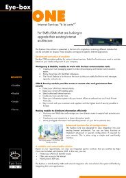
1.2 Product Overview<br />
Extended Communication Server is a powerful collaboration <strong>and</strong> mobility solution for small <strong>and</strong><br />
medium-sized enterprises (SMEs) including:<br />
- a set of collaboration tools to share information efficiently within a team, a group, a project,<br />
or the company<br />
- a mobile, secure <strong>and</strong> easy access to all enterprise collaboration tools<br />
- a unified communication solution integrated with OmniPCX Office<br />
- a secure Web management <strong>and</strong> an easy deployment<br />
- a full set of information technology (IT) servers<br />
- a Web hosting server<br />
Extended Communication Server is a key component of Office Communication Solutions.<br />
1-1
Chapter 1 <br />
1.3 Hardware Description<br />
Figure 1.1: Position in Office Communication Solutions<br />
The Extended Communication Server hardware platform is available in two editions:<br />
- The Compact edition is a desktop server, also rack-mountable, designed for small<br />
companies with up to 25 users.<br />
- The Premium edition is a rack shelf platform designed for medium enterprises with from<br />
25 to 200 users.<br />
Both Extended Communication Server editions are managed in the same way. Unless<br />
explicitly specified, all information <strong>and</strong> procedures included in this document apply to both<br />
Compact edition <strong>and</strong> Premium edition.<br />
1-2
Figure 1.2: Hardware Platforms<br />
The following table lists Compact <strong>and</strong> Premium edition platform characteristics.<br />
table 1.1: Hardware Platform Characteristics<br />
Compact Edition Premium Edition<br />
- Via C3 1.5 GHz processor<br />
- 512 Mb RAM<br />
- 160 Gb 7200 hard disk drive<br />
- 3 RJ-45 10/100 Mbps Ethernet<br />
interfaces<br />
- 1 PCI port (*)<br />
- 1 console port<br />
- 1 VGA port<br />
- 1 printer port<br />
1.4 User Profiles <strong>and</strong> Graphical Interfaces<br />
- Processor Intel® Core 2 Duo E6320<br />
- Chipset Intel E3000 (Mukilteo-2)<br />
- 2 Gb DDR2-667 SDRAM<br />
- 3x HDD 250 / 500 Gb Hot-swap SATA-2<br />
- 3x network Gigabytes Interfaces (RJ-45)<br />
- Graphical Function ATI ES 1000<br />
- DVD_ROM slimline<br />
- 2x Front USB 2.0 Ports<br />
- 1 Serial COM Port<br />
- Alim. 300 Watt<br />
The Extended Communication Server accepts three kinds of users:<br />
<br />
- One administrator, who manages the user accounts <strong>and</strong> controls <strong>and</strong> monitors all<br />
resources <strong>and</strong> features, such as network architecture, security measures, e-mail facilities,<br />
Web access, etc. Administration is done using a graphical administration interface.<br />
- A number of users, who manage their own accounts <strong>and</strong> benefit from available services<br />
through a graphical user interface called the Virtual Desktop. Users can also access these<br />
services from the Mobile Virtual Desktop using mobile terminals such as PDA (Personal<br />
Digital Assistant).<br />
1-3
Chapter 1 <br />
- Some delegated administrators, who are users that have a limited set of administration<br />
rights. A delegated administrator can access both the Virtual Desktop <strong>and</strong> the graphical<br />
administration interface limited to some menus.<br />
The administrator <strong>and</strong> the users access the graphical administration interface or the Virtual<br />
desktop in the same way, using a Web browser. When the user logs on, the Extended<br />
Communication Server serves whether the graphical administration interface or the Virtual<br />
Desktop according to the user identity <strong>and</strong> password that have been typed in. A delegated<br />
administrator can swap from the Virtual Desktop to the graphical administration interface, or<br />
vice versa, by the means of graphical buttons only available to delegated-administrator profile<br />
users.<br />
Note:<br />
The administrator is not exactly a user as he is not registered in the user database. The administrator<br />
must create a user account for himself if he needs to access the Virtual Desktop.<br />
1.4.1 Graphical Administration Interface<br />
The graphical administration interface access is via a secured connection (https) using any<br />
st<strong>and</strong>ard Web browser (Internet Explorer, Mozilla Firefox, Netscape Navigator...). The<br />
administrator accesses this interface from the local network or remotely, over the Internet. As<br />
an alternative, he can display the administration interface on a screen connected directly on<br />
the server, together with a keyboard <strong>and</strong> a mouse.<br />
The administration interface is an easy-to-use tool providing four main menus to manage the<br />
Extended Communication Server, the services, the end-users, <strong>and</strong> control <strong>and</strong> monitor the<br />
traffic.<br />
1-4
Figure 1.3: Graphical Administration Interface<br />
All menus provide a set of submenus, which the administrator access from the left-h<strong>and</strong> panel<br />
or by clicking corresponding icons. According to his own preference, the administrator can<br />
minimize the left h<strong>and</strong> panel for accessing the submenus through icons only.<br />
The administration interface provides a permanent help button ( ) the administrator can click<br />
whatever menu or submenu is displayed. This opens a pop-up window, which provides a<br />
useful contextual online help. Each help page is printable.<br />
Figure 1.4: Contextual Online Help Example<br />
Using the intuitive administration interface together with the online help, the administrator can<br />
explore the number of available features <strong>and</strong> services the Extended Communication Server<br />
provides.<br />
1.4.2 Virtual Desktop<br />
<br />
A user Connects to the Virtual Desktop in the same way the administrator connects to the<br />
administration interface except that the name <strong>and</strong> password are those of a st<strong>and</strong>ard user.<br />
1-5
Chapter 1 <br />
When the Virtual Desktop session is open, the user can manage his services: Web mails,<br />
calendar, contacts, favorite sites, <strong>and</strong> so on.<br />
Figure 1.5: View of the Virtual Desktop<br />
The Virtual Desktop consists of a set of intuitive interface controls to manage the services <strong>and</strong><br />
a comprehensive online help to obtain information when needed.<br />
1.5 Introduction to <strong>Installation</strong> <strong>and</strong> Configuration<br />
This document introduces the first steps an administrator is recommended to follow when<br />
installing the Extended Communication Server in the customer premises <strong>and</strong> configuring the<br />
network <strong>and</strong> services.<br />
These steps are further detailed in next chapters.<br />
table 1.2: <strong>Installation</strong> <strong>and</strong> Configuration First-steps Summary<br />
Recommended<br />
order<br />
Steps Objectives<br />
Step 1 Installing <strong>and</strong> starting-up Start up the server <strong>and</strong> access the graphical<br />
administration interface<br />
Step 2 Unlocking the software pack Unlock the software pack <strong>and</strong> access all<br />
administration interface menus<br />
Step 3 Network <strong>configuration</strong> Insert the server in the customer network<br />
<strong>and</strong> access the Web<br />
1-6
Recommended<br />
order<br />
Steps Objectives<br />
Step 4 Registration, software activation<br />
<strong>and</strong> updates<br />
Access the technical support, activate the<br />
full license <strong>and</strong> benefit from the last software<br />
packss<br />
Step 5 User management Create user accounts <strong>and</strong> manage user<br />
rights<br />
Step 6 Security management Control outgoing <strong>and</strong> incoming flows of<br />
traffic<br />
Step 8 Voice <strong>and</strong> data convergence Associate user accounts with phoning facilities<br />
Step 9 Messaging management Allow users to send <strong>and</strong> receive messages<br />
within the LAN <strong>and</strong> over the Internet<br />
Additional chapters describe useful functionalities that can be implemented later.<br />
1.6 Before <strong>Installation</strong><br />
First of all, we recommend you to read this document <strong>and</strong> examine the customer needs<br />
thoroughly.<br />
You should then prepare the Extended Communication Server installation considering the<br />
following topics:<br />
- Network architecture:<br />
• LAN<br />
• DMZ (Demilitarized Zone)<br />
• Internet Access<br />
- IP addressing plan, including:<br />
• Local machines that need static addresses<br />
• Dynamic assignment planning<br />
- Information from the ISP (Internet Service Provider), such as IP addresses of the DNS<br />
servers.<br />
- Public domain name<br />
- User management, including:<br />
• User groups<br />
• User accounts<br />
• User access rights to services<br />
• Delegated administrators, if any<br />
- Security policy, including firewall <strong>and</strong> proxy management<br />
<br />
1-7
Chapter 1 <br />
1-8
2 <br />
After reading this chapter, you will be able to start up the Extended Communication Server <strong>and</strong><br />
access the graphical administration interface.<br />
2.1 Introduction<br />
Two modes are provided for accessing the administration interface for the first time:<br />
- A direct access, the server being equipped with a screen, a keyboard <strong>and</strong> a mouse<br />
- From a local PC connected to the server<br />
Figure 2.1: Using a Direct Access or a Local PC<br />
2.2 Starting Up with a Direct Access<br />
To start up <strong>and</strong> access the Extended Communication Server administration interface with a<br />
direct access<br />
1. Unpack the server.<br />
2. Connect the power cable.<br />
3. Connect a screen, a keyboard <strong>and</strong> a mouse to the server.<br />
The server has one VGA port for connecting the screen, <strong>and</strong> PS/2 ports or USB ports for<br />
connecting a keyboard <strong>and</strong> a mouse.<br />
4. Switch on the server.<br />
2-1
Chapter 2 <br />
The Linux Kernel starts up.<br />
5. At the login prompt:<br />
• Type the default identifier: superadmin<br />
• Type the default password: %rV&A1uc<br />
• Click OK<br />
The integrated Web browser starts up.<br />
6. A message warns you that you are about to enter a secured session. Click yes to continue.<br />
7. A login dialog <strong>box</strong> is displayed:<br />
• Type the default identifier: superadmin<br />
• Type the default password: %rV&A1uc<br />
• Click OK<br />
You have now access to the administration interface.<br />
2.3 Starting Up from a Local PC<br />
To start up the Extended Communication Server from a local PC<br />
1. Unpack the server.<br />
2. Connect the power cable.<br />
3. Switch on the server.<br />
4. Using an Ethernet crossover cable, connect the local PC to the LAN1 (eth0) Ethernet<br />
interface of the server.<br />
Note 1:<br />
If the PC Ethernet port is "autosensing", an Ethernet straight cable can also be used.<br />
Note 2:<br />
Both Compact <strong>and</strong> Premium edition platforms have three Ethernet interfaces. Looking at the back<br />
panel, the LAN1 Ethernet port (eth0) is the left-most Ethernet port.<br />
2-2
Figure 2.3: Ethernet Port Locations<br />
5. Check that the PC network settings are compatible with the server default settings.<br />
The server default network settings are:<br />
• IP address: 192.168.92.1<br />
• Network mask: 255.255.255.0<br />
• Dynamic Host Configuration Protocol (DHCP) is not activated<br />
Any address from 192.168.92.2 to 192.168.92.254 is then suitable.<br />
6. Using a st<strong>and</strong>ard Web browser, type https://192.168.92.1<br />
7. A message warns you that you are about to enter a secured session. Click yes to continue.<br />
8. A login dialog <strong>box</strong> is displayed:<br />
<br />
2-3
Chapter 2 <br />
• Type the default identifier: superadmin<br />
• Type the default password: %rV&A1uc<br />
• Click OK<br />
You have now access to the administration interface.<br />
2.4 Administration Interface Limited Access<br />
The first time you starts up the Extended Communication Server <strong>and</strong> enters an administration<br />
session, most of menus are not accessible to you because the software pack is locked.<br />
A useful Quick Start Guide displayed on the left-h<strong>and</strong> side guides you through the very first<br />
steps of the server <strong>configuration</strong>, such as selecting the language <strong>and</strong> unlocking the software<br />
pack by entering the product license (also described in next chapters). You can use the Quick<br />
Start Guide in combination with this document. The Quick Start Guide ban be closed if needed<br />
<strong>and</strong> reopened later using the question mark icon located in the top banner of the left-h<strong>and</strong><br />
panel.<br />
Figure 2.5: The Quick Start Guide<br />
2-4
3 <br />
After reading this chapter, you will be able to unlock the administration-interface software pack.<br />
You will then have a full access to the administration menus.<br />
3.1 Principles<br />
The full license activation consists of two steps:<br />
1. Software pack unlocking. This is the aim of this chapter. When this task is completed,<br />
the software pack is unlocked for 31 days. During this limited period of time, also called the<br />
trial period, all features <strong>and</strong> services are available.<br />
2. License activation. You can perform this task immediately after software pack unlocking<br />
or later, within the 31-day trial period.<br />
. It is easier to perform this task after the Internet access has been installed. The license<br />
can be then activated online, by a simple click. Otherwise, the license activation key must<br />
be entered <strong>manual</strong>ly. After license has been activated, all features <strong>and</strong> services remain<br />
available for an unlimited duration.<br />
3.2 How to Unlock the Software Pack<br />
To unlock the software pack:<br />
1. You first need to obtain the software key (also called licence number) that corresponds to<br />
the product. You can retrieve the software key on the <strong>Alcatel</strong>-<strong>Lucent</strong> Business Partner<br />
Web site (http://www.businesspartner.alcatel-lucent.com/), accessing the following page:<br />
ONLINE SERVICES > eBuy > e-Licenses Services > My ECS Keys<br />
2. Once you have obtained the software key, open the administration interface <strong>and</strong> select the<br />
Appliance management > Licences & Releases > Packs & licences menu.<br />
3. Select the New pack tab.<br />
4. In the Activation Key or Licence number field, enter the software key.<br />
5. Click OK.<br />
3-1
Chapter 3 <br />
After the software pack has been unlocked, the panel foot displays information about the<br />
licence including the number of days that are remaining before the trial period will end.<br />
Remember that you will have to activate the product license within this trial period.<br />
Figure 3.2: After the Software Pack Has Been Unlocked<br />
3-2
4 <br />
After reading this chapter, you will be able to insert the Extended Communication Server in the<br />
customer network <strong>and</strong> access the Internet from the administration interface.<br />
4.1 Principles<br />
The three network interfaces <strong>and</strong> the comprehensive set of available <strong>configuration</strong> parameters<br />
the Extended Communication Server provides allow you to insert it in any network<br />
architecture.<br />
However, this document does not intend to consider all possible architectures. It aims at<br />
explaining you the basics, while giving you some useful examples corresponding to most usual<br />
situations.<br />
Below is an example of the way a Extended Communication Server can be inserted in a<br />
st<strong>and</strong>ard network topology:<br />
- The LAN (Local Area Network) is connected to interface eth0 (LAN1).<br />
- The Internet access is connected to interface eth1.<br />
- The DMZ (Demilitarized Zone) is connected to interface eth2. A DMZ is a LAN subnetwork<br />
that contains the external services accessible from the Internet, such as a Web server or<br />
an FTP server. Using a DMZ for external services, facilitates the security management.<br />
Figure 4.1: A St<strong>and</strong>ard Network Topology<br />
This chapter details the main Service management > Network service management<br />
submenus you should deal with in the following order:<br />
4-1
Chapter 4 <br />
1. General Network Parameters<br />
2. Network connections. After you have configured the network connections, you can<br />
access the Internet from the administration Interface (unless a remote proxy controls the<br />
Internet access, see the note below).<br />
3. DHCP. After you have activated the DHCP (Dynamic Host Configuration Protocol) service,<br />
you can access the administration interface <strong>and</strong> the Virtual Desktop from any workstation<br />
located in the LAN. As an alternative, it is possible to assign a static IP address to each<br />
machine of the LAN.<br />
Note:<br />
An additional section deals with the Remote proxy submenu. Follow this section instructions if a remote<br />
proxy controls the Internet access (usually, in large companies only).<br />
4.2 General Network Parameters<br />
To set the general network parameters:<br />
1. Select the Service management > Network service management > General Network<br />
Parameters menu.<br />
The general network parameter form is displayed.<br />
2. In the Appliance host name field, enter the server name that will identify the server in the<br />
network. Any name can be used.<br />
3. In the Appliance domain name field, enter the name of the domain the server belongs to,<br />
such as "mycompany.com".<br />
Important:<br />
The domain name is later used in many other settings, such as email addresses.<br />
4. If the WAN access address is dynamically assigned or if it is a PPPoE connection, the first<br />
<strong>and</strong> second name resolution servers are assigned automatically.<br />
Else assign them <strong>manual</strong>ly:<br />
• In the First name resolution server field, enter the DNS (Domain Name System)<br />
server address provided by the ISP (Internet Service Provider).<br />
• In the Second name resolution server field, enter the second DNS server address<br />
provided by the ISP. The second DNS server address is optional.<br />
5. Click OK.<br />
4-2
4.3 Network Connections<br />
Figure 4.2: Setting the General Network Parameters<br />
4.3.1 General Points on Network Connection Configuration<br />
4.3.1.1 Network Interfaces<br />
Both Compact <strong>and</strong> Premium edition servers have three network interfaces. Depending on the<br />
server edition <strong>and</strong> version, network interfaces may be labelled or not on the back panel.<br />
Anyway, we call in this document LAN1 the Ethernet interface eth0, which corresponds to the<br />
left-most back-panel RJ-45 port. LAN1 is the eth0 default name.<br />
All three interfaces can equally be used for any network connection.<br />
At the first start, only interface LAN1 exists by default, as an Ethernet LAN connection. You<br />
cannot delete this connection or modify its type, but you can modify all other settings.<br />
4.3.1.2 Network Connection Types<br />
When creating a new network connection, you must select its type among one of the five<br />
following options:<br />
- WAN ADSL PPPoE<br />
- Ethernet LAN<br />
- Ethernet Bridge<br />
- Ethernet LAN DMZ<br />
- Ethernet LAN Alias<br />
These five options are further described in next sections.<br />
4.3.1.3 Network Connection List<br />
<br />
To access the connection list select the Service management > Network service<br />
4-3
Chapter 4 <br />
management > Network connections menu.<br />
A list of existing connections is displayed.<br />
From this list you can:<br />
- create a new connection by clicking the Add button<br />
- configure an existing connection by clicking the modification button<br />
4.3.2 WAN ADSL PPPoE Connection<br />
A WAN ADSL PPPoE connection marks the border between the private <strong>and</strong> the public area.<br />
In example below, the Internet is accessed via an external ADSL modem. The eth1 IP address<br />
is public.<br />
Figure 4.4: WAN ADSL PPPoE Connection on eth1<br />
To create or configure an WAN ADSL PPPoE connection:<br />
1. Select the Service management > Network service management > Network<br />
4-4
connections menu. This opens the connection list.<br />
2. If you are creating a new connection:<br />
a. Click Add.<br />
b. Select the WAN ADSL PPPoE option<br />
c. Click OK.<br />
Otherwise, if you are modifying an existing WAN ADSL PPPoE connection:<br />
a. Select the WAN ADSL PPPoE connection in the list.<br />
b. Click the modification button .<br />
3. In the displayed form, enter the connection name. You can give any name that clearly<br />
identifies the connection.<br />
4. The WAN connection can be dynamically configured by the ISP.<br />
If it is not configured automatically:<br />
a. Enter the PPPoE settings given by the ISP (connection identifier, connection password<br />
<strong>and</strong> confirmation).<br />
b. Select whether the DNS server addresses provided by the ISP should be used<br />
(recommended).<br />
5. Select the Ethernet interface (eth1/eth2 if available).<br />
6. Activate the interface by selecting Yes.<br />
7. Validate the settings by clicking OK.<br />
4.3.3 LAN Ethernet Connection<br />
Within the private area, network interfaces must have the LAN Ethernet connection type. In<br />
figure below <strong>and</strong> considering the Internet access, the interface eth0 IP address is private while<br />
the router IP address is public. The LAN1 interface is also a LAN Ethernet connection<br />
Figure 4.5: Ethernet LAN Connections on eth0 <strong>and</strong> eth1<br />
To create or configure an Ethernet LAN connection:<br />
<br />
4-5
Chapter 4 <br />
1. Select the Service management > Network service management > Network<br />
connections menu. This opens the connection list.<br />
2. If you are creating a new connection:<br />
a. Click Add.<br />
b. Select the Ethernet LAN option<br />
c. Click OK.<br />
Otherwise, if you are modifying an existing Ethernet LAN connection:<br />
a. Select the Ethernet LAN connection in the list.<br />
b. Click the modification button .<br />
3. In the displayed form, enter the connection name. You can give any name that clearly<br />
identifies the connection.<br />
4. Select whether the network connection IP address is static or assigned by a DHCP server.<br />
If the network connection IP address is assigned by an external DHCP server, skip next<br />
step.<br />
5. Enter the network connection settings:<br />
• Network connection IP address.<br />
• Network mask or equivalent prefix.<br />
• If there is an external gateway (case of a default gateway to the Internet only), enter<br />
the gateway address.<br />
Note:<br />
This field does not concern a router used to access an internal subnetwork. If there is no external<br />
gateway, let the gateway field empty.<br />
6. If several network interfaces are available, select the Ethernet interface (ethx). This field is<br />
read-only in all other cases.<br />
7. Activate the interface by selecting Yes.<br />
8. Validate the settings by clicking OK.<br />
4.3.4 Ethernet Bridge Connection<br />
This option creates an Ethernet bridge between two interfaces or more. This merges related<br />
interfaces in one subnetwork.<br />
As an example, a Wi-Fi interface can be bridged on interface LAN1 so that the local network<br />
extends to the Wi-Fi devices. (see figure below).<br />
4-6
Figure 4.6: Bridge Connection of a Wi-Fi interface on LAN1<br />
To create or configure an Ethernet bridge connection:<br />
1. Select the Service management > Network service management > Network<br />
connections menu. This opens the connection list.<br />
2. If you are creating a new connection:<br />
a. Click Add.<br />
b. Select the Ethernet bridge option<br />
c. Click OK.<br />
Otherwise, if you are modifying an existing Ethernet bridge connection:<br />
a. Select the Ethernet bridge connection in the list.<br />
b. Click the modification button .<br />
3. In the displayed form, enter the connection name. You can give any name that clearly<br />
identifies the connection.<br />
4. If the bridge does not concern LAN1, enter the Ethernet bridge IP settings.<br />
Otherwise check the LAN1 check<strong>box</strong>. As a consequence, IP setting fields are<br />
automatically filled in.<br />
5. Select the interfaces that are involved in the Ethernet bridge.<br />
6. Activate the interface by selecting Yes.<br />
7. Validate the settings by clicking OK.<br />
4.3.5 Ethernet LAN DMZ Connection<br />
<br />
Use an "Ethernet LAN DMZ" connection to connect a local demilitarized-zone network, which<br />
will be accessible from the Internet as shown in figure: A St<strong>and</strong>ard Network Topology .<br />
4-7
Chapter 4 <br />
To create or configure an Ethernet LAN DMZ connection:<br />
1. Select the Service management > Network service management > Network<br />
connections menu. This opens the connection list.<br />
2. If you are creating a new connection:<br />
a. Click Add.<br />
b. Select the Ethernet LAN DMZ option<br />
c. Click OK.<br />
Otherwise, if you are modifying an existing Ethernet LAN DMZ connection:<br />
a. Select the Ethernet LAN DMZ connection in the list.<br />
b. Click the modification button .<br />
3. In the displayed form, enter the connection name. You can give any name that clearly<br />
identifies the connection.<br />
4. Enter the network connection settings:<br />
• Network connection IP address.<br />
• Network mask or equivalent prefix.<br />
• If there is an external gateway, enter the gateway address.<br />
5. If several network interfaces are available, select the Ethernet interface (ethx). This field is<br />
read-only in all other cases.<br />
6. Activate the interface by selecting Yes.<br />
7. Validate the settings by clicking OK.<br />
4.3.6 Ethernet LAN Alias Connection<br />
Use an "Ethernet LAN Alias" connection to create a virtual interface from an existing one. In<br />
this way, you can assign different IP addresses to one physical network interface.<br />
To create or configure an Ethernet LAN Alias connection:<br />
1. Select the Service management > Network service management > Network<br />
connections menu. This opens the connection list.<br />
2. If you are creating a new connection:<br />
a. Click Add.<br />
b. Select the Ethernet LAN Alias option<br />
c. Click OK.<br />
Otherwise, if you are modifying an existing Ethernet LAN Alias connection:<br />
a. Select the Ethernet LAN Alias connection in the list.<br />
b. Click the modification button .<br />
3. In the displayed form, enter the connection name. You can give any name that clearly<br />
identifies the connection.<br />
4. Enter the network connection settings:<br />
• Network connection IP address.<br />
• Network mask or equivalent prefix.<br />
5. If several network interfaces are available, select the physical Ethernet interface (ethx).<br />
This field is read-only otherwise.<br />
4-8
6. Activate the interface by selecting Yes.<br />
7. Validate the settings by clicking OK.<br />
4.4 DHCP Service<br />
If the DHCP service is activated on a given network interface, the Extended Communication<br />
Server is the DHCP server for all the peripherals that belongs to the corresponding<br />
subnetwork. In that case, the server assigns a dynamic IP address each time it detects a new<br />
client peripheral, which avoids maintaining static addresses <strong>manual</strong>ly.<br />
In example below, the DHCP service is activated on LAN1.<br />
Figure 4.7: DHCP Service Activated on LAN1<br />
The DHCP service is accessible through the Service management > Network service<br />
management > DHCP submenu. It provides three tabs, described in the following sections.<br />
Note:<br />
After you have configured the DHCP service, you must activate it by selecting the Active option.<br />
4.4.1 Global Configuration<br />
To configure the DHCP service:<br />
1. Select the Global <strong>configuration</strong> tab.<br />
2. Select the appropriate network connection.<br />
<br />
4-9
Chapter 4 <br />
3. Specify the duration of a DHCP lease, i.e. the length of time for which the IP address<br />
allocation is valid.<br />
4. Specify the IP address range reserved for DHCP (start of range, end of range).<br />
5. Enter the gateway IP address (generally, the address of the concerned network interface).<br />
6. Enter the DNS server IP addresses:<br />
• If the DNS service is activated, enter here the address of the concerned network<br />
interface.<br />
• If the DNS service is not activated, enter here the DNS server addresses provided by<br />
the ISP.<br />
7. Enter the WINS server IP addresses (optional). WINS st<strong>and</strong>s for Windows Internet Name<br />
Service, which is used for Windows network sharing.<br />
• If the DNS service is activated, enter here the address of the concerned network<br />
interface.<br />
• If the DNS service is not activated, enter here the DNS server addresses provided by<br />
the ISP.<br />
8. Click OK.<br />
4.4.2 Machines Declared<br />
Use the Machines declared tab to specify particular behaviors considering the DHCP service,<br />
such as:<br />
- One machine needs a static IP address (for example a server, or a printer).<br />
- You want to limit the DHCP service to a particular list of machines (for example to avoid<br />
that visitors equipped with laptop computers can connect to the local network).<br />
To declare a machine:<br />
1. Select the Machines declared tab.<br />
2. Select the appropriate network connection.<br />
3. Give any name that clearly identifies the machine in the network.<br />
4. Enter its MAC address. A Media Access Control address (MAC address) is a unique<br />
identifier attached to the machine network adapter.<br />
5. Select whether this machine IP address is static or dynamic (assigned by the DHCP<br />
server).<br />
6. If the machine IP address is static, enter its IP address. This address must be in the<br />
concerned network <strong>and</strong> outside the IP address range reserved for DHCP.<br />
7. Click OK.<br />
4.4.3 DHCP Leases<br />
The DHCP leases tab is for consultation only. It lists the DHCP leases that have been<br />
assigned to machines.<br />
4.5 Remote Proxy<br />
4-10
Some large organizations use their own proxies (not hosted on the Extended Communication<br />
Server) to control access to the Internet. If this is the case, you must configure the remote<br />
proxy access in order to allow the server to reach the Internet, which is m<strong>and</strong>atory for the<br />
automatic update feature.<br />
To access the Internet through a remote proxy:<br />
1. Select the Service management > Network service management > Remote proxy<br />
menu.<br />
This displays the remote-proxy access <strong>configuration</strong>-form.<br />
2. Select the following option: The Internet connection goes through the following remote<br />
proxy.<br />
3. Enter the access parameters that fit the remote proxy <strong>configuration</strong>:<br />
• Remote-proxy IP address<br />
• Listening port<br />
• Authentication by login <strong>and</strong> password, if any<br />
4. Click OK.<br />
<br />
4-11
Chapter 4 <br />
4-12
5 <br />
<br />
After reading this chapter, you will be able to access the Extended Communication Server<br />
online technical-support, to activate the full license <strong>and</strong> to update the software packs.<br />
5.1 General Points<br />
As you can now access the Internet from the administration interface, it is the right moment to<br />
activate the license for an unlimited duration <strong>and</strong> update the software packs. Updating the<br />
software packs offers you the guarantee that you benefit from the last software developments.<br />
They may also correct any software malfunction.<br />
You must first register your Extended Communication Server product before you can perform<br />
the license activation <strong>and</strong> any software update.<br />
5.2 Registering <strong>and</strong> Generating the Activation Key<br />
The Extended Communication Server product registration is m<strong>and</strong>atory for accessing the<br />
technical support.<br />
To register a product <strong>and</strong> generate the activation key:<br />
1. From any PC connected to the Internet, go to the <strong>Alcatel</strong>-<strong>Lucent</strong> Extended Communication<br />
Server-support Web site (http://support.rightvision.com/).<br />
2. If you already have a user account:<br />
a. Enter your login <strong>and</strong> password, <strong>and</strong> click OK.<br />
b. Select On-line services > Registering.<br />
c. Follow the instructions given to you.<br />
5-1
Chapter 5 <br />
If you do not have a user account:<br />
a. Select On-line services > Registering.<br />
b. Enter the contract number or Extended Communication Server serial number <strong>and</strong> click<br />
OK. You can find the serial number on a sticker that is stuck on the server chassis.<br />
c. Follow the instructions for creating your user account.<br />
d. Once created, use this account to log in.<br />
3. Select On_line services > Activation of my licenses.<br />
4. Enter the requested ID number. You can find this ID number in the administration interface<br />
using the Appliance management > Licences & Releases > Software Releases menu.<br />
5. Click on the button.<br />
6. Enter the license number.<br />
An activation key is then generated, that you will use to activate the license from the<br />
administration interface. If you want to activate the license <strong>manual</strong>ly, copy this activation<br />
key <strong>and</strong> paste it in any text file.<br />
5.3 Activating the License<br />
You must perform a license activation before the 31-day trial period ends.<br />
To activate the license:<br />
1. Select the Appliance management > Licences & Releases > Packs & licences menu.<br />
2. Select the New pack tab.<br />
5-2
3. Two activation methods are available to you:<br />
• If Internet can be accessed, perform an online activation by clicking the ACTIVATE<br />
button.<br />
• If Internet is not accessible, use the activation key you previously stored in a text file<br />
(see § Registering <strong>and</strong> Generating the Activation Key ).<br />
Copy this activation key, paste it in the Activation Key or Licence number field, <strong>and</strong><br />
click OK.<br />
When the license activation has completed successfully, the New pack tab displays an history<br />
of licenses.<br />
Figure 5.4: History of Licenses After License Activation<br />
5-3
Chapter 5 <br />
5.4 Software Updates<br />
The Extended Communication Server system is pre-configured for updating automatically from<br />
the Web on a per week basis.<br />
Note 1:<br />
Some software packs cannot be updated automatically. They must be updated <strong>manual</strong>ly.<br />
We recommend you to:<br />
- Keep the automatic update always on.<br />
- Perform a <strong>manual</strong> update after installation or after the server has been reset.<br />
To perform a <strong>manual</strong> update:<br />
1. Select the Appliance management > Appliance updates > Update from the web menu.<br />
2. Click the MANUAL UPDATE button.<br />
3. Follow the instructions given to you.<br />
Note 2:<br />
Some exceptional updates may need the use of a CD-Rom or a USB device. In such a case, use the Ap-<br />
pliance management > Appliance updates > Update from CD-ROM / USB menu <strong>and</strong> follow the in-<br />
structions given to you.<br />
5-4
6 <br />
After reading this chapter, you will have an overview of user group <strong>and</strong> user account<br />
management. Please refer to online help for details.<br />
6.1 General Points<br />
The way the users are distributed in user groups should reflect the enterprise structure, meet<br />
the enterprise needs, <strong>and</strong> prepare for future evolutions. We recommend you to plan the way<br />
you will distribute the users in user groups before creating groups <strong>and</strong> accounts.<br />
The Extended Communication Server administrator manages two types of user groups:<br />
- St<strong>and</strong>ard groups<br />
Each user belongs to one st<strong>and</strong>ard group or subgroup. You must create first a st<strong>and</strong>ard<br />
group or subgroup before you can create related user accounts.<br />
- Virtual groups. A user can belong to none or several virtual groups. You can create virtual<br />
groups at any time <strong>and</strong> affect any existing user account to anyone of them.<br />
Here below is an example of the way st<strong>and</strong>ard <strong>and</strong> virtual groups can be used to describe an<br />
enterprise.<br />
Figure 6.1: Example of a Structure<br />
There are several ways to create users in the ECS directory:<br />
- Via administration comm<strong>and</strong>s: the administrator creates users one by one<br />
- Via the synchronization tool: users are imported from a remote database. This must be a<br />
6-1
Chapter 6 <br />
Microsoft® Active Directory<br />
6.2 ECS Directory Management<br />
6.2.1 User Groups <strong>and</strong> User Accounts<br />
Select the Directory > User accounts menu to manage user groups <strong>and</strong> user accounts.<br />
The displayed form is divided into two parts:<br />
- The left-h<strong>and</strong> side part is the group zone. It is composed of the user group list <strong>and</strong><br />
associated management buttons.<br />
- The right-h<strong>and</strong> side part is the user zone. It is composed of the user account list <strong>and</strong><br />
associated management buttons.<br />
_<br />
_<br />
_<br />
c<br />
h<br />
a<br />
n<br />
g<br />
e<br />
-<br />
b<br />
e<br />
g<br />
i<br />
n<br />
_<br />
_<br />
_<br />
_<br />
_<br />
_<br />
c<br />
h<br />
a<br />
n<br />
g<br />
e<br />
-<br />
e<br />
n<br />
d<br />
_<br />
_<br />
_<br />
6.2.1.1 Creating User Groups<br />
To create a user group:<br />
Figure 6.2: Group Zone <strong>and</strong> User Zone<br />
1. If you are about to create a st<strong>and</strong>ard group, select the parent group (the root group or an<br />
existing group) in the left-h<strong>and</strong> side of the form.<br />
2. Click Add.<br />
3. Enter the name of the group.<br />
4. Select whether the group is St<strong>and</strong>ardor Virtual.<br />
5. Describe it if necessary.<br />
6. Enter the group email address. An email sent to this address will be received by all the<br />
6-2
users of the group.<br />
7. Click OK.<br />
After you have created a group:<br />
- If it is a st<strong>and</strong>ard group , you can create user accounts for it.<br />
- If it is a virtual group , you can add already existing user accounts in it. In a virtual<br />
group, users are considered as guests that are invited into the group.<br />
6.2.1.2 Creating User Accounts<br />
Note 1:<br />
You must have first created a st<strong>and</strong>ard group or subgroup before you can add a user account to it.<br />
To create a user account:<br />
1. In the left-h<strong>and</strong> side of the form, select the st<strong>and</strong>ard group or subgroup to which the user<br />
will belong.<br />
2. In the right-h<strong>and</strong> side of the form, click Add.<br />
3. Enter the user description (name, first name, <strong>and</strong> so on). A star * comes before fields that<br />
are m<strong>and</strong>atory.<br />
4. Select whether the user account is active or not. A user account is active by default. This<br />
option makes it possible to deactivate a user account instead of deleting it.<br />
5. Assign disk space quotas to the user account if necessary.<br />
6. Specify FTP service access <strong>and</strong> Web access authorizations.<br />
7. Specify the user privileges, if any. User privileges are further discussed in next section.<br />
8. Assign e-mail addresses to the user.<br />
9. If necessary, allow the user to send <strong>and</strong> receive emails that are managed by a remote<br />
server (remote messaging).<br />
10. Click OK.<br />
Note 2:<br />
The administration interface also offers you the possibility to import user accounts using the CSV<br />
(Comma-separated Values) format. To do this, select the Directory > Users Import/Export > Users im-<br />
port (CSV format) menu <strong>and</strong> follow the online help instructions. Among other explanations, the online<br />
help fully describes the CSV format.<br />
6.2.2 User Privileges<br />
You can assign special roles to some users:<br />
- One Delegated administrator per user group can manage the user accounts of this group<br />
or of another group. This person can add / modify / delete user accounts, <strong>and</strong> assign some<br />
access rights to services. Web sites, such as an Intranet site, can be on the responsibility<br />
of a delegated administrator.<br />
- One Virtual Desk graphic designer is responsible for the Virtual Desktop graphical<br />
charter (logo, colors, etc.)<br />
- One News administrator is responsible for the news distribution to all users<br />
<br />
6-3
Chapter 6 <br />
- One News administrator for the group is responsible for the news distribution to the<br />
users of the group<br />
6.3 External Directory Synchronization<br />
6.3.1 Synchronization Overview<br />
Synchronization is used to import users from a Microsoft® Active Directory’s to the Extended<br />
Communication Server LDAP directory. All remote users are imported from this directory.<br />
This method removes the task of creating each contact individually.<br />
_<br />
_<br />
_<br />
c<br />
h<br />
a<br />
n<br />
g<br />
e<br />
-<br />
b<br />
e<br />
g<br />
i<br />
n<br />
_<br />
_<br />
_<br />
_<br />
_<br />
_<br />
c<br />
h<br />
a<br />
n<br />
g<br />
e<br />
-<br />
e<br />
n<br />
d<br />
_<br />
_<br />
_<br />
Other features:<br />
- Automatic daily synchronization<br />
Figure 6.3: Synchronization Overview<br />
- Possibility to work in mixed mode with users created in the Extended Communication<br />
Server directory only<br />
6-4
- Exclusion of some accounts from the synchronization<br />
- Visibility of deactivated accounts in Active Directory<br />
User features:<br />
- All Extended Communication Server services are available for imported users (Virtual<br />
desktop, Email, FTP, mobility, FAX …)<br />
- Password management is deactivated on Extended Communication Server<br />
6.3.2 Configuration<br />
6.3.2.1 External Directory Configuration<br />
_<br />
_<br />
_<br />
c<br />
h<br />
a<br />
n<br />
g<br />
e<br />
-<br />
b<br />
e<br />
g<br />
i<br />
n<br />
_<br />
_<br />
_<br />
_<br />
_<br />
_<br />
c<br />
h<br />
a<br />
n<br />
g<br />
e<br />
-<br />
e<br />
n<br />
d<br />
_<br />
_<br />
_<br />
To configure the external directory:<br />
1. Navigate to Directory > Synchronization with an external directory (Active Directory)<br />
2. Select the Configuration tab. The External directory connection <strong>configuration</strong> page is<br />
displayed:<br />
Figure 6.4: External Directory Configuration Page<br />
<br />
3. Fill in the fields:<br />
• IP address or name of the external directory: enter the IP address or the name of<br />
the external directory<br />
• DN of the link account: enter the DN (Distinguished Name) of the link account. This<br />
account must "Read" enable to access the information contained in the directory.<br />
Example of DN: cn=link link,cn=user,dc=domain,dc=loc<br />
6-5
Chapter 6 <br />
• Link account password: enter the user password as defined in DN of the link<br />
account<br />
• Directory domain: this field is automatically completed from the domain defined in<br />
DN of the link account. It can be modified.<br />
This field represents the domain to which the external directory belongs.<br />
• Base from which the synchronization will be done: enter the field specifying the<br />
sub-tree of the directory from where the synchronization is performed.<br />
For example: dc=domain,dc=loc<br />
• Base group in which the users will be retrieved: enter the target group name where<br />
the users are to be placed<br />
• Time when the automatic synchronization will start: select the time of the daily<br />
synchronization<br />
• Encrypt the connection with the Active Directory server: validate the check <strong>box</strong> to<br />
encrypt information between the remote directory <strong>and</strong> Extended Communication<br />
Server.<br />
To do this, you can import the public part of the authority certificate used on the Active<br />
Directory in ASCII(Base64) format. This option can be used without importing the<br />
authority certificate.<br />
4. Click OK<br />
This operation generates an LDAP (port 389) or LDAPS (port 636) connection to the Active<br />
Directory server according to the security option.<br />
Note:<br />
In the case of LDAPS synchronization with the Active Directory server, the Extended Communication<br />
Server server asks the superadmin to authenticate again.<br />
If parameters sent by the Extended Communication Server are correct, the Active Directory<br />
server returns the user list.<br />
The administrator can exclude some users from the synchronization (See the Exclusion tab).<br />
6.3.2.2 How-to Retrieve the Link Account Information in the Windows® Server<br />
The link account is an Active Directory user with admin rights. It must be created in the<br />
windows server with the Active Directory users <strong>and</strong> computers administrative tool. See below<br />
an example of link account link link is created in the group Domain Admin.<br />
_<br />
_<br />
_<br />
c<br />
h<br />
a<br />
n<br />
g<br />
e<br />
-<br />
b<br />
e<br />
g<br />
i<br />
n<br />
_<br />
_<br />
_<br />
6-6
_<br />
_<br />
_<br />
c<br />
h<br />
a<br />
n<br />
g<br />
e<br />
-<br />
b<br />
e<br />
g<br />
i<br />
n<br />
_<br />
_<br />
_<br />
_<br />
_<br />
_<br />
c<br />
h<br />
a<br />
n<br />
g<br />
e<br />
-<br />
e<br />
n<br />
d<br />
_<br />
_<br />
_<br />
_<br />
_<br />
_<br />
c<br />
h<br />
a<br />
n<br />
g<br />
e<br />
-<br />
e<br />
n<br />
d<br />
_<br />
_<br />
_<br />
Figure 6.5: User Properties Example<br />
The DN of the link account has the following form :<br />
cn=name,cn=Users,dc=domain,dc=domain_extension.<br />
Example with an Active Directory domain named domain.loc :<br />
cn=link link,cn=Users,dc=domain,dc=loc<br />
The base from which the synchronization is performed has the following form:<br />
dc=domain,dc=domain_extension<br />
Example with an Active Directory domain named domain.loc:<br />
dc=domain,dc=loc<br />
This information can be retrieved from the Active Directory server with an LDAP browser. Here<br />
is an example of use of the LDAP browser from the Windows® server:<br />
1. Enter the comm<strong>and</strong>: Start / Run /ldp.exe.<br />
The LDAP Connect window is displayed:<br />
<br />
6-7
Chapter 6 <br />
_<br />
_<br />
_<br />
c<br />
h<br />
a<br />
n<br />
g<br />
e<br />
-<br />
b<br />
e<br />
g<br />
i<br />
n<br />
_<br />
_<br />
_<br />
_<br />
_<br />
_<br />
c<br />
h<br />
a<br />
n<br />
g<br />
e<br />
-<br />
e<br />
n<br />
d<br />
_<br />
_<br />
_<br />
_<br />
_<br />
_<br />
c<br />
h<br />
a<br />
n<br />
g<br />
e<br />
-<br />
b<br />
e<br />
g<br />
i<br />
n<br />
_<br />
_<br />
_<br />
Figure 6.6: LDAP Connection<br />
2. LDAP Connection: enter the information for the LDAP to the connect to the server <strong>and</strong><br />
click OK<br />
The Bind window is displayed:<br />
Figure 6.7: User Binding<br />
3. Bind type : select Bind as currently logged on user <strong>and</strong> click OK<br />
The search window is displayed:<br />
6-8
_<br />
_<br />
_<br />
c<br />
h<br />
a<br />
n<br />
g<br />
e<br />
-<br />
e<br />
n<br />
d<br />
_<br />
_<br />
_<br />
_<br />
_<br />
_<br />
c<br />
h<br />
a<br />
n<br />
g<br />
e<br />
-<br />
b<br />
e<br />
g<br />
i<br />
n<br />
_<br />
_<br />
_<br />
_<br />
_<br />
_<br />
c<br />
h<br />
a<br />
n<br />
g<br />
e<br />
-<br />
e<br />
n<br />
d<br />
_<br />
_<br />
_<br />
Figure 6.8: Searching a User<br />
4. Search the users in the database: fill the appropriate fields <strong>and</strong> click Run<br />
Example of result of a search:<br />
Important:<br />
Figure 6.9: Search Result<br />
When the connection from the Extended Communication Server to the Active Directory fails, it is<br />
recommended to perform some connection tests from a LDAP browser installed on a client PC.<br />
The connection from the Extended Communication Server does not work as long as the connec-<br />
tion from the LDAP browser does not work. In this case, check the Windows® server configura-<br />
tion <strong>and</strong> parameters.<br />
6.3.2.3 Synchronization<br />
<br />
Once the user list is retrieved from the Active Directory server, the administrator can change<br />
the service status to On in order to activate the service.<br />
Click the Synchronize button at the bottom of the frame in order to launch the first<br />
6-9
Chapter 6 <br />
synchronization.<br />
This operation will retrieve the user information from Active Directory <strong>and</strong> create the users in<br />
the Extended Communication Server base group. The retrieved information are:<br />
- User login<br />
- User first name<br />
- User last name<br />
- Phone number<br />
- Mobile phone number<br />
- Email addresses<br />
Once the first synchronization is done, you can activate the daily synchronization process<br />
which will repeat the operation described above.<br />
6.3.2.4 Deactivated Account<br />
This list presents user accounts deleted or deactivated in the external directory. They have<br />
been deactivated on the Extended Communication Server server. They will be activated again<br />
if the account is reactivated or recreated in the external directory. They are available in this<br />
interface so that they can be deleted by the administrator.<br />
6.3.3 User Connection<br />
6.3.3.1 User Authentication<br />
Users authenticate to the Extended Communication Server services by using their usual Active<br />
Directory login/password.<br />
The first time, the Extended Communication Server forwards the authentication request to the<br />
Active Directory server <strong>and</strong> saves locally the encrypted password.<br />
If the user is successfully authenticated, any following requests are h<strong>and</strong>le directly by the<br />
Extended Communication Server until the user password is changed.<br />
6.3.3.2 Login Policy<br />
On Extended Communication Server a user login must be made up of the following characters:<br />
[a..z],[A..Z],[0..9],[-],[_].<br />
The Extended Communication Server login policy is more restrictive than the Active Directory<br />
login policy where special characters are allowed.<br />
- Special characters are replaced according to the following table:<br />
Special<br />
Characters<br />
Replacement<br />
Characters<br />
Special<br />
Characters<br />
table 6.1: Conversion Rules<br />
@ á é í ó ú ý Á É Í Ó Ú Ý<br />
a a e i o u y A E I O U Y<br />
à è ì ò ù À È Ì Ò Ù<br />
6-10
Replacement<br />
Characters<br />
Special<br />
Characters<br />
Replacement<br />
Characters<br />
Special<br />
Characters<br />
Replacement<br />
Characters<br />
Special<br />
Characters<br />
Replacement<br />
Characters<br />
a e i o u A E I O U<br />
ä ë ï ö ü ÿ Ä Ë Ï Ö Ü<br />
a e i o u y A E I O U<br />
â ê î ô û Â Ê î Ô Û<br />
a e i o u A E I O U<br />
å Å # Ø ß ç Ç ã ñ õ Ã Ñ Õ<br />
a A o O s c C a n o A N O<br />
- Other ASCII characters are converted as follows:<br />
ASCII Code Range Replacement Characters Exceptions<br />
00-1F [nothing]<br />
20-2F _ (underscore)<br />
3A-40 _ (underscore) "@" (Hex: 40) is replaced with "a"<br />
5B-60 _ (underscore) "\" (Hex: 5c) is simply removed<br />
7B-FF [nothing] Many characters h<strong>and</strong>led as<br />
shown in the above table<br />
For more information on ASCII table visit: http://www.asciitable.com.<br />
6.3.3.3 Passwords Policy<br />
On Extended Communication Server, a user password can only use the following characters: [<br />
a-z A-Z 0-9 _ / \ & ~ " # ' { } ( ) [ ] < > ` @ = ? ; : ! + . , % $ * - ].<br />
Important:<br />
As long as passwords are imported from Active Directory (without possible modification on Ex-<br />
tended Communication Server), passwords on Active Directory must be made up of characters<br />
belonging to the above list.<br />
6.3.3.4 Restrictions<br />
The number of users which can be imported cannot exceed the maximum number of licensed<br />
users.<br />
For imported users, the following information cannot be modified:<br />
- Password<br />
6.3.4 LOGS<br />
- Phone information<br />
<br />
6-11
Chapter 6 <br />
The system logs for this service are available in:<br />
Control panel / system logs/tab System in the file:<br />
/var/log/syslog<br />
6-12
7 <br />
This chapter introduces you to the different possibilities the Extended Communication Server<br />
offers for managing information security <strong>and</strong> for monitoring traffic. After reading it, you will be<br />
able to plan the organization information security <strong>and</strong> implement it.<br />
7.1 Overview<br />
For managing security, the Extended Communication Server is equipped with:<br />
- An internal proxy server<br />
- An internal firewall<br />
By default, the firewall is active but the proxy server is not active.<br />
Note:<br />
We recommend you to configure <strong>and</strong> activate proxy <strong>and</strong> firewall services.<br />
Moreover, for a better network security, we recommend you to use the Extended Communication Server<br />
options: Kaspersky, for an efficient antivirus protection.<br />
7.2 Firewall Management<br />
7.2.1 General Points<br />
When it is activated, a firewall filters the flows of traffic circulating between the different<br />
network interfaces. Its main role is to separate the organization internal information <strong>and</strong><br />
resources from the Internet traffic.<br />
Firewall management consists in specifying rules that authorize or forbid a given service or<br />
group of services for a given flow.<br />
7.2.1.1 Traffic Flows<br />
A traffic flow is defined by:<br />
- Two endpoints. For example LAN1 (connected to the organization LAN) <strong>and</strong> the network<br />
interface connected to the Internet.<br />
- The traffic sense. For example, from LAN1 to the network interface connected to the<br />
Internet.<br />
The administration interface automatically displays existing traffic flows according to the<br />
network interfaces you have created.<br />
7.2.1.2 Services <strong>and</strong> Service Groups<br />
A service is defined by:<br />
- A name. It can be any name, usually the service protocol name (for example HTTP).<br />
- A port number. Port numbers identify sending <strong>and</strong> receiving applications. For example,<br />
port 80 identifies the http service.<br />
- A transport protocol: TCP (Transmission Control Protocol) or UDP (User Datagram<br />
Protocol).<br />
7-1
Chapter 7 <br />
The system h<strong>and</strong>les a preexisting list of services that you can consult thanks to the Service<br />
management > Security > Firewall > Services <strong>and</strong> service groups menu, selecting the<br />
Services tab. You can also add new services to this list for specific needs.<br />
Figure 7.1: List of Available Services<br />
Services can be gathered into service groups to facilitate the firewall management. For<br />
example a group called MAIL which contains SMTP, POP <strong>and</strong> IMAP services, can be used to<br />
authorize or forbid all three services in one single operation.<br />
Some service groups preexist in the system. Using the Service groups tab, you can display<br />
existing groups <strong>and</strong> add your own groups if needed.<br />
7.2.1.3 Firewall Rules<br />
Figure 7.2: List of Service Groups<br />
The administration interface provides two different views on existing rules:<br />
- The Basic settings menu displays the main rules that protect the network, grouped by<br />
7-2
main flows. Use this menu to have an overview on firewall rules or for basic needs.<br />
- The Advanced settings menu displays all available flows <strong>and</strong> associated rules. Use this<br />
menu if you have specific needs.<br />
By default, all services are forbidden.<br />
_<br />
_<br />
_<br />
c<br />
h<br />
a<br />
n<br />
g<br />
e<br />
-<br />
b<br />
e<br />
g<br />
i<br />
n<br />
_<br />
_<br />
_<br />
_<br />
_<br />
_<br />
c<br />
h<br />
a<br />
n<br />
g<br />
e<br />
-<br />
e<br />
n<br />
d<br />
_<br />
_<br />
_<br />
7.2.2 Firewall Advanced Settings<br />
Figure 7.3: The Basic Settings Tabbed-panel<br />
<br />
The Extended Communication Server automatically creates all the rules you need to manage<br />
the firewall according to the network interfaces you have declared. Usually, all you have to do<br />
is to modify the preexisting rules to authorize or forbid a given service on a given flow.<br />
However, you may have to create rules <strong>manual</strong>ly in specific cases. The example below<br />
describes a situation where a part of the LAN is hidden behind a router (from the server point<br />
of view). A new rule must be created to authorize services to the subnetwork users (mail<br />
service, in our procedure example).<br />
7-3
Chapter 7 <br />
To create a rule for such a subnetwork:<br />
Figure 7.4: A LAN Including a Subnetwork<br />
1. Select the Service management > Security > Firewall > Advanced settings menu.<br />
2. Select the Computer, networks tab.<br />
3. In the Name of new group or network field, enter a name for the subnetwork.<br />
4. Click Create.<br />
A creation form is displayed.<br />
a. In this form, select the network option.<br />
b. Enter the network address <strong>and</strong> mask.<br />
c. Click OK.<br />
7-4
_<br />
_<br />
_<br />
c<br />
h<br />
a<br />
n<br />
g<br />
e<br />
-<br />
b<br />
e<br />
g<br />
i<br />
n<br />
_<br />
_<br />
_<br />
The new item is added to the list of computers <strong>and</strong> networks.<br />
5. Select the Rules tab<br />
6. Using the drop-down lists located at the top of the form, select the flow (in our example,<br />
from MySubnetwork to Appliance).<br />
7. Click Create a new rule.<br />
A rule creation form is displayed.<br />
<br />
a. In this form, select a service or a service group (in our example, the MAIL service<br />
group). It is also possible to create new services from this form if necessary.<br />
b. Click Add.<br />
c. Click OK.<br />
The rule is now displayed in the rule list.<br />
7-5
Chapter 7 <br />
_<br />
_<br />
_<br />
c<br />
h<br />
a<br />
n<br />
g<br />
e<br />
-<br />
e<br />
n<br />
d<br />
_<br />
_<br />
_<br />
Select the Order level of the new rule.<br />
The firewall scans messages from the lowest order rule to the highest order rule. The first<br />
rule which matches decides if a message is allowed or refused.<br />
que se passe t il qu<strong>and</strong> aucune regle ne match?????<br />
The three service protocols of the MAIL service group (i.e. SMTP, POP, IMAP) are authorized<br />
for this flow.<br />
Note:<br />
After you have created the firewall rules, we recommend you to save them via the Service management<br />
> Security > Firewall > Back up <strong>and</strong> restore rules menu.<br />
7.3 Proxy Server Management<br />
7.3.1 Proxy Services<br />
The proxy server is an internal application which processes the client workstation requests to<br />
the Internet <strong>and</strong> provides the following services:<br />
- Caching service. If the caching service is active, the proxy server keeps local copies of<br />
the different client requests. In this way, it can serve a request by retrieving content from<br />
previous requests instead of contacting remote servers. This significantly saves b<strong>and</strong>width<br />
while increasing performance.<br />
The caching service also provides statistics on Web traffic.<br />
- Web access control. The proxy server can permit or block Web access for each user<br />
7-6
individually.<br />
- Web filtering. Web filtering is done through black <strong>and</strong> white lists of URLs or keywords that<br />
forbid or authorize access to certain Web sites. Filters apply to all users or to specific user<br />
groups.<br />
Note:<br />
These services need that the client Web browser is configured so that the Web traffic is sent to the proxy<br />
server.<br />
Important:<br />
If the proxy server is used for Web traffic control <strong>and</strong> filtering, the firewall should block http <strong>and</strong><br />
https traffic. Blocking direct Web access forces Web traffic to pass through the proxy server,<br />
which is essential to an efficient control <strong>and</strong> filtering service.<br />
7.3.2 Activating the Proxy Cache Service<br />
To activate the proxy cache service:<br />
Figure 7.9: Web Access Through the Proxy Server Only<br />
1. Select the Service management > Network service management > Proxy Cache<br />
Service menu.<br />
2. Change the Activate Proxy Cache option to On.<br />
7.3.3 Web Access Control<br />
To control Web access:<br />
1. Select the Service management > Security > Web access control menu.<br />
2. For each user, select whether the Web access is permitted or forbidden.<br />
3. Select On to activate the User Web browsing control .<br />
<br />
7-7
Chapter 7 <br />
7.3.4 Web Filtering<br />
Figure 7.10: The Web Access Control Form<br />
The Web filtering service relies on lists of URLs <strong>and</strong> keywords that prohibit/authorize access:<br />
- Black lists. A black list contains all URLs or keywords for which users cannot access<br />
related contents. All other contents are accessible.<br />
Examples 1:<br />
forbiddensite.com, sex, .mp3<br />
- White lists. A white list contains all URLs or keywords for which users can access related<br />
contents. All other contents are not accessible.<br />
Note:<br />
Examples 2:<br />
www.alcatel-lucent.com, .edu<br />
The proxy cache service must be active for the Web filtering to be effective.<br />
7.3.4.1 All-User Web-Access Filtering<br />
To filter all-user Web access:<br />
1. Select the Service management > Security > Black <strong>and</strong> White lists menu.<br />
2. select the Main lists tab.<br />
3. Click the button that corresponds to the list you want to modify (black or white list).<br />
4. In the List tab.<br />
• Enter the URLs <strong>and</strong>/or keywords.<br />
• Click OK.<br />
Note:<br />
Lists can also be modified by export/import facilities.<br />
7-8
5. If you want the list to be automatically updated from an FTP server:<br />
a. Select the Update tab.<br />
b. Enter the FTP server characteristics: name, path, etc.<br />
c. Click OK.<br />
6. Come back to the Main lists menu.<br />
7. Enable the list by clicking Enabled.<br />
7.3.4.2 User-Group Web-Access Filtering<br />
To filter user-group Web access:<br />
Figure 7.11: Black <strong>and</strong> White Lists For All Users<br />
1. Select the Service management > Security > Black <strong>and</strong> White lists menu.<br />
2. select the Lists by group tab.<br />
3. In the Lists by group form:<br />
a. Enter the list name.<br />
b. Select whether the list is a white list or a black list.<br />
c. Click ADD.<br />
The new list is now displayed in the form.<br />
4. Click the button to modify the new list.<br />
5. In the List tab.<br />
• Enter the URLs <strong>and</strong>/or keywords.<br />
• Click OK.<br />
Note:<br />
Lists can also be modified by export/import facilities.<br />
6. In the Groups tab, select the concerned groups.<br />
7. If you want the list to be automatically updated from an FTP server:<br />
a. Select the Update tab.<br />
b. Enter the FTP server characteristics: name, path, etc.<br />
<br />
7-9
Chapter 7 <br />
c. Click OK.<br />
8. Come back to the Lists by group menu.<br />
9. Enable the Black <strong>and</strong> White lists by group filtering by clicking On.<br />
7.3.5 Client Configuration<br />
Figure 7.12: Black <strong>and</strong> White Lists For User Groups<br />
Client workstations must be configured so that they can access the proxy server.<br />
To configure a client workstation Web browser:<br />
1. Go to the browser connection settings.<br />
For example, for Microsoft Internet Explorer:<br />
a. Select the Tools > Internet Options menu.<br />
b. Select the Connections tab.<br />
c. Click the LAN Settings button<br />
7-10
Figure 7.13: Example of Settings (Microsoft Internet Explorer)<br />
Other Web browsers have equivalent settings.<br />
2. Enter the proxy server address. For example, if the workstation belongs to the LAN<br />
connected to LAN1, then the proxy server address is the LAN1 IP address.<br />
3. Enter the proxy port number: 8080.<br />
7.3.6 Proxy Cache Statistics<br />
You can also use the proxy cache to examine the Web traffic <strong>and</strong> generate reports.<br />
To activate proxy cache statistics:<br />
1. Select the Control panel > Proxy cache flow analysis menu.<br />
2. At the Activate/de-activate statistics option, click On.<br />
7.4 Certificates Management<br />
7.4.1 Overview<br />
A certificate is an electronic document which incorporates a digital signature to bind together a<br />
key with an identity. The signature is delivered by a CA (Certification Authority).<br />
Among other information, a certificate includes:<br />
- the organization name<br />
- a validity period<br />
- The digital signature.<br />
<br />
The Extended Communication Server hosts its own certification authority. This CA signs the<br />
certificates delivered by the server for all secured services.<br />
7-11
Chapter 7 <br />
7.4.2 Creating a User Certificate<br />
To create a user certificate:<br />
1. Select the Service management > Certificate management menu.<br />
2. Select the User certificates tab.<br />
3. To create a private certificate:<br />
a. Click New.<br />
This displays a form.<br />
b. Enter requested information that identifies the organization.<br />
c. Give a name to the certificate.<br />
d. Click OK.<br />
The certificate is created, but is not yet valid as it is not signed.<br />
e. Select the certificate <strong>and</strong> copy it to clipboard.<br />
4. Select the Certification authorities tab.<br />
5. Using , open the certification authority panel.<br />
6. Select the Signing a request tab.<br />
7. Paste the certificate you had copied.<br />
8. Enter the validity period.<br />
9. Click OK.<br />
The certificate is now signed <strong>and</strong> valid.<br />
7-12
7.4.3 Using a Certificate<br />
Once the user certificate is created, it must be assigned to services. The example below<br />
shows how to affect the certificate to the Web access service.<br />
To assign a certificate to the Web access service:<br />
1. Select the Appliance management > Configuring the access from an Internet<br />
connection menu.<br />
2. Select the SSL certificate tab<br />
3. Select the desired certificate.<br />
Figure 7.16: Certificate Assignment to Web Access Service<br />
Security alert messages relating to certificates may concern:<br />
- The date validity, which may have expired.<br />
- The name validity, which may not match the site name.<br />
- The certification authority, which may be unknown.<br />
<br />
7-13
Chapter 7 <br />
Figure 7.17: Security Alert Example<br />
To avoid the security alert shown in figure above, you must install the CA certificate on your<br />
client device.<br />
To install the CA certificate:<br />
1. Select the Service management > Certificate management menu.<br />
2. Select the Certification authorities tab.<br />
3. Using , open the certification authority panel.<br />
4. Click Click here to export the certificate.<br />
5. A dialog <strong>box</strong> offers you several options:<br />
• Click Open to install the certificate on the current machine. This supposes that you<br />
repeat this procedure on each machine.<br />
• Click Save to install later the certificate on all machines, from the file you are saving.<br />
7.4.4 Enabling Automatic Regeneration of Certificates<br />
A certificate depends on the host name of the Extended Communication Server. As such, it<br />
must be regenerated each time the host name is modified. Provided the corresponding option<br />
is enabled, certificates can be automatically regenerated each time the hostname of the<br />
Extended Communication Server is modified.<br />
1. Select the Service management > Network service management > General Network<br />
Parameters menu.<br />
If you have already generated <strong>and</strong> signed certificates, the window displays a Regenerate<br />
the SSL certificate by default form.<br />
7-14
2. Select whether you wish the certificates to be automatically regenerated when the host<br />
name is changed. Click yes or no.<br />
3. Select the services on which the new certificates are to apply.<br />
<br />
7-15
Chapter 7 <br />
7-16
8 <br />
Read this chapter if your Extended Communication Server works together with an OmniPCX<br />
Office. After reading it, you will be able to carry out Internet <strong>and</strong> telephone services<br />
convergence.<br />
8.1 General Points<br />
The voice/data convergence service allows users to access the telephone functions from the<br />
Virtual Desktop <strong>and</strong> benefit from additional services on telephone terminals: call forwarding,<br />
unified messaging, click to call, <strong>and</strong> so on.<br />
Figure 8.1: Voice <strong>and</strong> data convergence<br />
The extended communication pack must be installed so that you can access the OmniPCX<br />
Office menu in the Service management panel.<br />
8-1
Chapter 8 <br />
Figure 8.2: OmniPCX Office Icon <strong>and</strong> menu<br />
8.2 Activating Voice <strong>and</strong> Data Convergence<br />
Note:<br />
For efficiency reasons, we recommend that both Extended Communication Server <strong>and</strong> OmniPCX Office<br />
belong to the same subnetwork.<br />
To activate voice <strong>and</strong> data convergence:<br />
1. Select the Service management >OmniPCX Office > Detection <strong>and</strong> Configuration<br />
menu.<br />
2. Select the IP detection tab.<br />
3. Click Detection of the OmniPCX Office IP address.<br />
After some seconds, the OmniPCX Office IP address is displayed.<br />
4. If automatic detection does not succeed: in the IP address OmniPCX Office field, enter<br />
the OmniPCX Office IP address<br />
5. Select the Country of the OmniPCX Office<br />
6. Select the Area code of the OmniPCX Office (optional)<br />
This information is used to convert a call number, retrieved from the Click to Call<br />
application, to a local area number or a national number before being transmitted to the<br />
OmniPCX Office.<br />
7. Click OK<br />
8. Change the Status of the Voice / Data convergence service option button to On.<br />
_<br />
_<br />
_<br />
c<br />
h<br />
a<br />
n<br />
g<br />
e<br />
-<br />
b<br />
e<br />
g<br />
i<br />
n<br />
_<br />
_<br />
_<br />
8-2
_<br />
_<br />
_<br />
c<br />
h<br />
a<br />
n<br />
g<br />
e<br />
-<br />
e<br />
n<br />
d<br />
_<br />
_<br />
_<br />
8.3 Retrieving information<br />
Figure 8.3: Voice <strong>and</strong> Data Convergence Service Activation<br />
After the service is activated, you can retrieve information from the OmniPCX Office:<br />
- Use the Synchronization of terminals menu to retrieve the list of telephone terminals or<br />
devices connected to the OmniPCX Office. This functionality allows you to manage user<br />
accounts <strong>and</strong> telephone terminal tables in a synchronized way.<br />
- Use the User import menu to help you creating user accounts from the OmniPCX Office<br />
user table. This retrieves information (name, first name, internal numbers) from the<br />
OmniPCX Office <strong>and</strong> create user accounts automatically. You can modify these accounts<br />
later to add information the Extended Communication Server requires.<br />
- Each synchronized terminal must be now associated with an existing user account or a<br />
new user account.<br />
Consult the online help for more information.<br />
<br />
8-3
Chapter 8 <br />
8-4
9 <br />
After reading this chapter, you will be able to manage internal <strong>and</strong> external email messaging.<br />
9.1 General Points<br />
The Extended Communication Server includes a mail server which can be used as a<br />
st<strong>and</strong>alone mail server or relayed by an external mail server.<br />
The Extended Communication Server mail service h<strong>and</strong>les the following protocols:<br />
- SMTP (Simple Mail transfer Protocol), to "push" email messages into email <strong>box</strong>es.<br />
- POP (Post Office Protocol) or IMAP (Internet Message Access Protocol) to "pull" email<br />
messages from email <strong>box</strong>es.<br />
SMTP service must be activated so that the messaging service can work properly, <strong>and</strong> one of<br />
POP or IMAP services if a fat mail client is used.<br />
As different <strong>configuration</strong>s can be used to make the messaging service available, following<br />
sections will introduce you to the messaging service settings in four steps:<br />
1. Internal messaging, so that users can exchange emails inside the organization.<br />
2. External messaging, so that users can send <strong>and</strong> receive messages via the Internet.<br />
3. Configuring for a fat mail client.<br />
4. Additional settings that may be useful according to the organization characteristics. You<br />
can also refer to the online help for more information.<br />
Note:<br />
We recommend you to test the messaging service from Virtual Desktop sessions.<br />
9.2 Internal Messaging<br />
To activate the internal messaging service:<br />
1. Select the Service management > Email > SMTP menu.<br />
2. Change the SMTP status option button to On.<br />
All users that have email addresses <strong>and</strong> authorizations can now exchange internal emails.<br />
9.3 Extending the Service to the Internet<br />
SMTP must be configured so that the mail service is extended to the Internet.<br />
To configure SMTP for the Internet:<br />
1. Select the Service management > Email > SMTP > Basic <strong>configuration</strong> menu.<br />
2. Select the Send method tab.<br />
3. Enter the email address that will receive messaging errors.<br />
4. If the enterprise has a public domain name, select Use Internet mode.<br />
With this option, the mail server exchanges emails directly with other mail servers over the<br />
Internet.<br />
9-1
Chapter 9 <br />
Note 1:<br />
You must verify that the MX (Mail eXchange) DNS record point the server public IP address. Contact<br />
the registrar that manages the domain name to verify this particular point.<br />
Figure 9.1: Direct Access to Mail Servers<br />
5. If the enterprise does not have a public domain name:<br />
a. Select Operate only in Relay mode.<br />
With this option, the mail server exchanges emails with a mail server of the ISP<br />
(Internet Service Provider). The ISP mail server operates as a relay for the Extended<br />
Communication Server mail server.<br />
Note 2:<br />
Relay name, login <strong>and</strong> password are then provided by the ISP.<br />
b. Enter the relay name or IP address.<br />
c. Enter the login <strong>and</strong> password if the ISP mail server need them.<br />
9-2
d. Click OK.<br />
Figure 9.2: Operating in Relay Mode<br />
9.4 Configuring for a Fat Mail Client<br />
Some additional settings are needed if a fat mail client, such as Microsoft Outlook or Mozilla<br />
Thunderbird, is used.<br />
On the server side, you must activate one of the POP/IMAP services:<br />
1. Select the Service management > Email > POP/IMAP menu.<br />
2. Change to On one of the POP status or IMAP status option buttons, or both.<br />
On the client side, you must configure each mail account in accordance with the server<br />
settings:<br />
- Protocol<br />
- User identifier <strong>and</strong> password<br />
9.5 Additional settings<br />
9.5.1 Domain names<br />
Use the Domain Names menu if several domain names are to be used.<br />
<br />
By default, the system manages only one domain name. This name is the main domain name<br />
9-3
Chapter 9 <br />
you declared in the General network parameters form. If the organization has several<br />
domain names, declare them to the system to optimize email processing. Email addresses that<br />
belong to domains declared to the system do not need external DNS queries.<br />
To declare a domain name to the system:<br />
1. Select the Service management > Email > SMTP > Domain names menu.<br />
2. Click Add.<br />
This opens a Declaration of the domain names managed by the appliance form.<br />
3. Enter the new domain name.<br />
Figure 9.3: Declaration of Domain Names Form<br />
4. For the Transport option:<br />
• Select Local if the mail server manages all emails belonging to this domain.<br />
• Select Via SMTP if several email servers manage emails belonging to this domain.<br />
When such an email is to be processed, the mail server tries first to process it from its<br />
own tables. If the email address is not found there, the message is sent to a next mail<br />
server via SMTP. You must specify this next mail server by its Server name <strong>and</strong><br />
Login/Password if required.<br />
Several mail servers can be chained this way.<br />
5. Click OK.<br />
Once the new domain name is declared, you can create new email addresses for each user<br />
who needs an email address with this domain name.<br />
Example below shows the list of domain names after a second domain name has been<br />
created.<br />
9-4
9.5.2 Anti-relay / Relay Authorisation<br />
Figure 9.4: List of Domain Names<br />
This feature aims at prevent malicious use of the mail server, such as spam relaying. Use this<br />
feature to control user authorizations for accessing mail services, especially for remote users.<br />
By default, users located behind the LAN1 interface are authorized to use the Extended<br />
Communication Server mail server as a relay to the Internet.<br />
To manage anti-relay / relay:<br />
1. Select the Service management >Email >SMTP > Anti-relay / Relay authorization<br />
menu.<br />
This opens a tabbed-panel, which first panel lists network interfaces <strong>and</strong> relay<br />
authorizations.<br />
Figure 9.5: Relay Authorization Tabbed-panel<br />
2. Select the desired network interfaces.<br />
Selecting the network interface only allow local users located behind this interface to<br />
access the Internet.<br />
For remote users, you must configure the authorizations described in next steps.<br />
3. To authorize the relay to the Internet by client authentication:<br />
• Click the Authentication tab.<br />
• Change Enable the relay to Yes.<br />
• Click OK.<br />
<br />
9-5
Chapter 9 <br />
Note:<br />
Remote users email-client must be configured to authenticate when accessing the service.<br />
4. To authorize the relay to the Internet by name or IP address:<br />
• Click the Name or IP address tab.<br />
• Click Add.<br />
• Enter the desired name or IP address.<br />
• Click OK.<br />
The other tabs (HELO/EHLO <strong>and</strong> Remote blacklist) can also be used to restrict the<br />
authorizations <strong>and</strong> filter the email addresses.<br />
9.5.3 Remote Email Service<br />
Use this menu to retrieve shared account emails or to authorize users to retrieve their personal<br />
email accounts.<br />
To activate the remote email service:<br />
1. Select the Service management >Email > Remote e-mail service menu.<br />
2. Select the Frequency tab.<br />
3. If you want to change the mail fetch frequency:<br />
• Enter the mail fetch frequency. Default is 15 minutes.<br />
• Click OK.<br />
4. Change the Synchronization status to On.<br />
These first steps are enough to allow users to manage personal email accounts via the<br />
Virtual Desktop.<br />
Use next steps, in addition, if emails are retrieved from shared accounts (a unique mail <strong>box</strong><br />
per domain) hosted by the ISP, or if emails are stored by the ISP <strong>and</strong> served on dem<strong>and</strong><br />
via an ETRN comm<strong>and</strong>, for example because of a non-permanent Internet connection.<br />
5. If shared accounts are to be managed:<br />
a. Select the Shared accounts tab.<br />
b. Select the protocol <strong>and</strong> enter required information that corresponds to the ISP mail<br />
server.<br />
c. Configure the fetching service.<br />
d. Click OK.<br />
6. If the remote server is an ETRN (Extended Turn) server:<br />
a. Select the ETRN tab.<br />
b. Enter the server name.<br />
c. Change Activate fetch to Yes.<br />
d. Click OK.<br />
9.5.4 Mail Filtering<br />
The mail filtering function consists of several filtering services that you can activate <strong>and</strong><br />
configure separately. These services filter on email addresses, on email contents or on<br />
attachments.<br />
9-6
Figure 9.6: Mail Filtering Services<br />
<br />
The Service management > Email > Mail filtering menu is divided in three submenus<br />
corresponding to three complementary services:<br />
- The Filter by grey list service use the greylisting method to filter received emails. The<br />
mail transfer agent temporarily rejects any email from a sender it does not recognize. If the<br />
email is legitimate, the originating server will try again to send it later, at which time the<br />
agent will accept it. If the email is from a spammer, it will probably not retry to send it.<br />
To avoid important emails to be delayed or rejected, the administrator maintains a White<br />
list that contains authorized addresses. The administrator can also allow users to h<strong>and</strong>le<br />
their own White lists.<br />
- The Anti-Virus/Anti-Spam e-mail content filtering service consists of three software<br />
plug-ins.<br />
• ClamAV (Clam AntiVirus) is an open source antivirus software toolkit which main use is<br />
to scan email viruses. ClamAV is pre-installed <strong>and</strong> license free. It does not scan http<br />
<strong>and</strong> ftp flows of traffic.<br />
• SpamAssassin is a software program used for email spam filtering. SpamAssassin is<br />
pre-installed <strong>and</strong> license free.<br />
• Kasperky is a powerful anti-virus software toolkit which needs a license to be activated.<br />
You can activate the service using the Configuration of the function menu <strong>and</strong> configure<br />
each plug-in separately.<br />
- The Filtering by type of attachment service filters according to the extension type or the<br />
MIME (Multipurpose Internet Mail Extensions) type of files attached to emails.<br />
9-7
Chapter 9 <br />
9-8
10 <br />
10.1 Overview<br />
The Instant Messaging application allows a user to:<br />
- Exchange instant messages with one or several users<br />
- Know the status of other users<br />
10.2 Server Configuration<br />
10.2.1 Configuration Overview<br />
To configure the Instant Messaging server:<br />
- Navigate to Service management > Instant messaging<br />
- Select the Basic parameters tab<br />
- Modify server options as described in the sections below<br />
- Click OK<br />
A popup window informs you that modifications are taken into account.<br />
10.2.2 Generic Parameters<br />
10.2.3 Options<br />
_<br />
_<br />
_<br />
c<br />
h<br />
a<br />
n<br />
g<br />
e<br />
-<br />
b<br />
e<br />
g<br />
i<br />
n<br />
_<br />
_<br />
_<br />
_<br />
_<br />
_<br />
c<br />
h<br />
a<br />
n<br />
g<br />
e<br />
-<br />
e<br />
n<br />
d<br />
_<br />
_<br />
_<br />
Figure 10.1: Generic Parameters Section<br />
- Administrator: select the Instant Messaging administrator.<br />
The administrator is able to sent notifications to all users (connected or not connected)<br />
- Domain of Identifiers: select the domain of the Instant Messaging users<br />
- Server public IP: enter your server address used by external users. This address is used<br />
for automatic creation of xmpp DNS entries.<br />
_<br />
_<br />
_<br />
c<br />
h<br />
a<br />
n<br />
g<br />
e<br />
-<br />
b<br />
e<br />
g<br />
i<br />
n<br />
_<br />
_<br />
_<br />
10-1
Chapter 10 <br />
_<br />
_<br />
_<br />
c<br />
h<br />
a<br />
n<br />
g<br />
e<br />
-<br />
e<br />
n<br />
d<br />
_<br />
_<br />
_<br />
Figure 10.2: Option Section<br />
- By default, allow connection server to server:<br />
• On: all instant messaging servers are allowed to connect to Extended Communication<br />
Server except servers belonging to the black list<br />
• Off: all instant messaging servers are not allowed to connect to Extended<br />
Communication Server except servers belonging to the white list<br />
- Authorize creation <strong>and</strong> use of chat rooms: users can create <strong>and</strong>/or use chat rooms<br />
(chat room is for heavy clients only)<br />
- Pre-fill of the buddy list:<br />
• None: user's buddy list are not pre-filled<br />
• With members of groups: buddy lists of users are automatically filled with members<br />
of their groups<br />
• With members of virtual groups: buddy lists of users are automatically filled with<br />
members of their virtual groups<br />
• With members of groups <strong>and</strong> virtual groups: buddy lists of users are automatically<br />
filled with members of their groups <strong>and</strong> virtual groups<br />
- Number of simultaneous sessions by user: enter the number of simultaneous chats per<br />
user<br />
10.2.4 Web Gateway<br />
_<br />
_<br />
_<br />
c<br />
h<br />
a<br />
n<br />
g<br />
e<br />
-<br />
b<br />
e<br />
g<br />
i<br />
n<br />
_<br />
_<br />
_<br />
10-2
_<br />
_<br />
_<br />
c<br />
h<br />
a<br />
n<br />
g<br />
e<br />
-<br />
e<br />
n<br />
d<br />
_<br />
_<br />
_<br />
Figure 10.3: Web Gateway Section<br />
- Activate the web gateways:<br />
• On: users can use some features only available through the web <strong>and</strong> to connect to the<br />
instant messaging without firewall restrictions.<br />
In addition, the Presence feature can be hosted on a remote server<br />
• Off: no web access is available<br />
- Website name: select the domain name used by Extended Communication Server users<br />
to access the web features<br />
- Listening interface for the web gateways: select the network interface used for FTP<br />
transfer. Only heavy client use FTP to transfer.<br />
- Authorize the web presence: this feature allows your users to display their availability on<br />
a website.<br />
- Activate web presence by default for all users: by activating this option, all the users<br />
can use the feature, otherwise they have to activate it through their instant messaging<br />
client.<br />
- Activate the http-polling:<br />
• On: specific clients can connect to the instant messaging application via a URL. For<br />
example: http://xmpp.domain.loc/http-poll/<br />
Note 1:<br />
All clients do not support this protocol<br />
• Off: all clients must use the 5222 port<br />
<br />
- Activate the files transfer proxy:<br />
• On: file transfers to users outside the Extended Communication Server domain are<br />
allowed<br />
10-3
Chapter 10 <br />
10.2.5 Gateways<br />
_<br />
_<br />
_<br />
c<br />
h<br />
a<br />
n<br />
g<br />
e<br />
-<br />
b<br />
e<br />
g<br />
i<br />
n<br />
_<br />
_<br />
_<br />
_<br />
_<br />
_<br />
c<br />
h<br />
a<br />
n<br />
g<br />
e<br />
-<br />
e<br />
n<br />
d<br />
_<br />
_<br />
_<br />
Note 2:<br />
The use of a proxy is not available on all instant messaging clients.<br />
• Off: no file transfer outside the Extended Communication Server domain<br />
Activate IRC gateway:<br />
Figure 10.4: Gateways Section<br />
You can allow your users to connect to some IRC servers<br />
- On: users, declared on this Extended Communication Server, can connect to a remote IRC<br />
(Internet Relay Chat) server<br />
- Off:<br />
10.2.6 Instant Messaging Status<br />
_<br />
_<br />
_<br />
c<br />
h<br />
a<br />
n<br />
g<br />
e<br />
-<br />
b<br />
e<br />
g<br />
i<br />
n<br />
_<br />
_<br />
_<br />
_<br />
_<br />
_<br />
c<br />
h<br />
a<br />
n<br />
g<br />
e<br />
-<br />
e<br />
n<br />
d<br />
_<br />
_<br />
_<br />
Instant messaging status:<br />
Figure 10.5: Instant Messaging Status<br />
- Click On to enable the instant messaging application<br />
- Click Off to disable the instant messaging application<br />
10.3 User Configuration<br />
To enable instant messaging, each individual user must be configured:<br />
- Navigate to : Directory > User accounts<br />
- Select the group<br />
10-4
_<br />
_<br />
_<br />
c<br />
h<br />
a<br />
n<br />
g<br />
e<br />
-<br />
b<br />
e<br />
g<br />
i<br />
n<br />
_<br />
_<br />
_<br />
_<br />
_<br />
_<br />
c<br />
h<br />
a<br />
n<br />
g<br />
e<br />
-<br />
e<br />
n<br />
d<br />
_<br />
_<br />
_<br />
- Select the user<br />
- Click Modify<br />
- In the Instant messaging section click:<br />
• On to allow instant messaging<br />
• Off to bar instant messaging<br />
10.4 DNS Configuration<br />
Figure 10.6: Instant Messaging Section in the User Properties<br />
When all users do not belong to the same domain or to the same network, the DNS server<br />
must be configured.<br />
When an external DNS is used, it must include the following lines:<br />
_jabber._tcp.mydomain.com SRV 5 0 5269 xmppserver.mydomain.com<br />
_xmpp-client._tcp.mydomain.com SRV 5 0 5222 xmppserver.mydomain.com<br />
_xmpp-server.mydomain.com SRV 5 0 5269 xmppserver.mydomain.com<br />
In the example above, the parameter Domain of Identifiers is set to mydomain.com.<br />
The external DNS server is configured in section: module Installing the system - Network<br />
Configuration § General Network Parameters .<br />
10.5 Configuration Example with Heavy Clients<br />
10.5.1 Inside the Same Domain <strong>and</strong> Same LAN<br />
_<br />
_<br />
_<br />
c<br />
h<br />
a<br />
n<br />
g<br />
e<br />
-<br />
b<br />
e<br />
g<br />
i<br />
n<br />
_<br />
_<br />
_<br />
<br />
10-5
Chapter 10 <br />
_<br />
_<br />
_<br />
c<br />
h<br />
a<br />
n<br />
g<br />
e<br />
-<br />
e<br />
n<br />
d<br />
_<br />
_<br />
_<br />
Figure 10.7: Configuration Example with Users in the Same Domain <strong>and</strong> Same LAN<br />
Instant Messaging <strong>configuration</strong>:<br />
- Domain of identifiers: mydomain.com<br />
- By default allow connection server to server: off<br />
- Authorize creation <strong>and</strong> use of chat rooms: off<br />
- Pref-fill of the buddy list: None<br />
- Number of simultaneous session by user: 1<br />
Firewall <strong>configuration</strong>:<br />
- Traffic LAN -> ECS on port 5222 (or 5223) must be allowed<br />
10.5.2 Inside the Same Domain with Different Networks<br />
_<br />
_<br />
_<br />
c<br />
h<br />
a<br />
n<br />
g<br />
e<br />
-<br />
b<br />
e<br />
g<br />
i<br />
n<br />
_<br />
_<br />
_<br />
10-6
_<br />
_<br />
_<br />
c<br />
h<br />
a<br />
n<br />
g<br />
e<br />
-<br />
e<br />
n<br />
d<br />
_<br />
_<br />
_<br />
Figure 10.8: Configuration Example with Users in the Same Domain <strong>and</strong> Different LAN<br />
Instant Messaging <strong>configuration</strong>:<br />
- Domain of identifiers: mydomain.com<br />
- By default allow connection server to server: off<br />
- Authorize creation <strong>and</strong> use of chat rooms: off<br />
- Pref-fill of the buddy list: None<br />
- Number of simultaneous session by user: 1<br />
Firewall <strong>configuration</strong>:<br />
- Traffic from LAN to ECS on port 5222 (or 5223) must be allowed<br />
- Traffic from WAN to ECS on port 5222 (or 5223) must be allowed<br />
10.5.3 Different Domains <strong>and</strong> Different Networks<br />
_<br />
_<br />
_<br />
c<br />
h<br />
a<br />
n<br />
g<br />
e<br />
-<br />
b<br />
e<br />
g<br />
i<br />
n<br />
_<br />
_<br />
_<br />
<br />
10-7
Chapter 10 <br />
_<br />
_<br />
_<br />
c<br />
h<br />
a<br />
n<br />
g<br />
e<br />
-<br />
e<br />
n<br />
d<br />
_<br />
_<br />
_<br />
Figure 10.9: Configuration Example with Users in the Different Domain <strong>and</strong> Different LAN<br />
Instant Messaging <strong>configuration</strong>:<br />
- Domain of identifiers: mydomain.com<br />
- By default allow connection server to server: on<br />
(or add the remote server name in the white list)<br />
- Authorize creation <strong>and</strong> use of chat rooms: off<br />
- Pref-fill of the buddy list: None<br />
- Number of simultaneous session by user: 1<br />
Firewall <strong>configuration</strong>:<br />
- Traffic LAN -> ECS on port 5222 (or 5223) must be allowed<br />
- Traffic WAN -> ECS on port 5269<br />
10.5.4 Different Domains <strong>and</strong> the Same Networks<br />
_<br />
_<br />
_<br />
c<br />
h<br />
a<br />
n<br />
g<br />
e<br />
-<br />
b<br />
e<br />
g<br />
i<br />
n<br />
_<br />
_<br />
_<br />
10-8
_<br />
_<br />
_<br />
c<br />
h<br />
a<br />
n<br />
g<br />
e<br />
-<br />
e<br />
n<br />
d<br />
_<br />
_<br />
_<br />
Figure 10.10: Configuration Example with Users in the Different Domain <strong>and</strong> Same LAN<br />
Instant Messaging <strong>configuration</strong>:<br />
- Domain of identifiers: mydomain.com<br />
- By default allow connection server to server: on<br />
(or add the remote server name in the white list)<br />
- Authorize creation <strong>and</strong> use of chat rooms: off<br />
- Pref-fill of the buddy list: None<br />
- Number of simultaneous session by user: 1<br />
Firewall <strong>configuration</strong>:<br />
- Traffic LAN -> ECS on port 5222 (or 5223) must be allowed<br />
- Traffic WAN ECS on port 5269 must be allowed<br />
<br />
10-9
Chapter 10 <br />
10-10
11 <br />
This document explains how to configure the fax server on the Extended Communication<br />
Server <strong>and</strong> OmniPCX Office.<br />
11.1 Overview<br />
The Extended Communication Server can host a fax server.<br />
The main technical characteristics of the fax server are:<br />
- The connections to OmniPCX Office uses SIP protocol<br />
- Communications from Extended Communication Server to the OmniPCX Office use the<br />
port number 5060<br />
- Communications from OmniPCX Office to the Extended Communication Server use the<br />
port number 5059<br />
- Protocols RTP <strong>and</strong> SRTP are supported<br />
- Connections from OmniPCX Office to the public network must be performed via ISDN or<br />
analogic lines. Public SIP providers are not supported.<br />
11.2 Configuration<br />
11.2.1 OmniPCX Office Configuration<br />
Compatibility: This feature is applicable with OmniPCX Office release R7.0 <strong>and</strong> higher.<br />
This paragraph describes the basic <strong>configuration</strong> for the following topology:<br />
_<br />
_<br />
_<br />
c<br />
h<br />
a<br />
n<br />
g<br />
e<br />
-<br />
b<br />
e<br />
g<br />
i<br />
n<br />
_<br />
_<br />
_<br />
_<br />
_<br />
_<br />
c<br />
h<br />
a<br />
n<br />
g<br />
e<br />
-<br />
e<br />
n<br />
d<br />
_<br />
_<br />
_<br />
11.2.1.1 SIP protocol <strong>configuration</strong><br />
_<br />
_<br />
_<br />
c<br />
h<br />
a<br />
n<br />
g<br />
e<br />
-<br />
b<br />
e<br />
g<br />
i<br />
n<br />
_<br />
_<br />
_<br />
Figure 11.1: FAX Server Overview<br />
11-1
Chapter 11 <br />
_<br />
_<br />
_<br />
c<br />
h<br />
a<br />
n<br />
g<br />
e<br />
-<br />
e<br />
n<br />
d<br />
_<br />
_<br />
_<br />
Figure 11.2: VOIP Parameters Settings 1<br />
- Number of VoIP-Trunk Channels: select a value # 2<br />
- VoIP Protocol: select SIP (a warm reset is required)<br />
_<br />
_<br />
_<br />
c<br />
h<br />
a<br />
n<br />
g<br />
e<br />
-<br />
b<br />
e<br />
g<br />
i<br />
n<br />
_<br />
_<br />
_<br />
11-2
_<br />
_<br />
_<br />
c<br />
h<br />
a<br />
n<br />
g<br />
e<br />
-<br />
e<br />
n<br />
d<br />
_<br />
_<br />
_<br />
Figure 11.3: VOIP Parameters Setting 2<br />
- H323 End of Dialing Timeout: select 5.0. By default, the OmniPCX Office uses a timer for<br />
outgoing calls on VoIP trunk (SIP / H.323)<br />
- End of Dialing table used: validate the check <strong>box</strong> <strong>and</strong> configure the associated table<br />
(Numbering - EoD Table)<br />
11.2.1.2 Traffic Sharing <strong>and</strong> Barring<br />
To allow Fax reception/transmission between the public network <strong>and</strong> the Extended<br />
Communication Server through <strong>Alcatel</strong>-<strong>Lucent</strong> OmniPCX Office Communication Server, do not<br />
forget to manage the traffic sharing & barring tables for the transit calls:<br />
Public trunk VoIP link<br />
11.2.1.3 Numbering Plan Configuration<br />
Configure the installation number:<br />
_<br />
_<br />
_<br />
c<br />
h<br />
a<br />
n<br />
g<br />
e<br />
-<br />
b<br />
e<br />
g<br />
i<br />
n<br />
_<br />
_<br />
_<br />
<br />
11-3
Chapter 11 <br />
_<br />
_<br />
_<br />
c<br />
h<br />
a<br />
n<br />
g<br />
e<br />
-<br />
e<br />
n<br />
d<br />
_<br />
_<br />
_<br />
Figure 11.4: <strong>Installation</strong> Numbers Settings<br />
In the public numbering plan, the Fax DDI number is sent to the ARS table:<br />
_<br />
_<br />
_<br />
c<br />
h<br />
a<br />
n<br />
g<br />
e<br />
-<br />
b<br />
e<br />
g<br />
i<br />
n<br />
_<br />
_<br />
_<br />
_<br />
_<br />
_<br />
c<br />
h<br />
a<br />
n<br />
g<br />
e<br />
-<br />
e<br />
n<br />
d<br />
_<br />
_<br />
_<br />
Figure 11.5: Public Numbering Plans Settings<br />
VoIP trunk is a private trunks: in the Private Numbering Plan, configure the prefix for outgoing<br />
calls to enable Fax transmission from Extended Communication Server to the public network<br />
(on Extended Communication Server, the prefix for public calls is configured with the value 0).<br />
11-4
_<br />
_<br />
_<br />
c<br />
h<br />
a<br />
n<br />
g<br />
e<br />
-<br />
b<br />
e<br />
g<br />
i<br />
n<br />
_<br />
_<br />
_<br />
_<br />
_<br />
_<br />
c<br />
h<br />
a<br />
n<br />
g<br />
e<br />
-<br />
e<br />
n<br />
d<br />
_<br />
_<br />
_<br />
11.2.1.4 ARS Configuration<br />
_<br />
_<br />
_<br />
c<br />
h<br />
a<br />
n<br />
g<br />
e<br />
-<br />
b<br />
e<br />
g<br />
i<br />
n<br />
_<br />
_<br />
_<br />
_<br />
_<br />
_<br />
c<br />
h<br />
a<br />
n<br />
g<br />
e<br />
-<br />
e<br />
n<br />
d<br />
_<br />
_<br />
_<br />
Figure 11.6: Private Numbering Plans Settings<br />
Figure 11.7: ARS Configuration Parameters<br />
<br />
(*) Reminder: the prefix for Fax DDI number is equal to the <strong>Installation</strong> Number plus the DDI<br />
11-5
Chapter 11 <br />
(91330 4000). If the <strong>Installation</strong> number is empty, then the prefix in the ARS table must be the<br />
DDI part only (prefix = 4000). In this case, the CLI send to the public exchange for outgoing<br />
calls will be the DDI part only <strong>and</strong> not the public number.<br />
11.2.2 Fax Call Routing (or Fax Call Switching)<br />
Since OmniPCX Office R7.1 it is possible to use the OmniPCX Office Fax Call Routing feature<br />
with the Extended Communication Server fax server.<br />
Reminder:<br />
- A unique DDI number is used for subscriber <strong>and</strong> fax call<br />
- General pre-announcement before call distribution must be configured<br />
- Control by the noteworthy address FaxCRActiv (must be enabled = 01)<br />
See OmniPCX Office Expert documentation fore more details.<br />
This paragraph describes the basic <strong>configuration</strong> for the following topology (based on the<br />
previous example, with the Fax 300):<br />
_<br />
_<br />
_<br />
c<br />
h<br />
a<br />
n<br />
g<br />
e<br />
-<br />
b<br />
e<br />
g<br />
i<br />
n<br />
_<br />
_<br />
_<br />
_<br />
_<br />
_<br />
c<br />
h<br />
a<br />
n<br />
g<br />
e<br />
-<br />
e<br />
n<br />
d<br />
_<br />
_<br />
_<br />
11.2.2.1 Create Virtual Terminals<br />
Figure 11.8: Fax Routing Example<br />
Constraints: as the Fax Call Routing feature in OmniPCX Office only allows an internal<br />
subscriber as a fax destination, it is necessary to use virtual terminal to route the user's fax<br />
11-6
EDN to the Extended Communication Server.<br />
Create 2 Virtual Terminals (one VT per user):<br />
_<br />
_<br />
_<br />
c<br />
h<br />
a<br />
n<br />
g<br />
e<br />
-<br />
b<br />
e<br />
g<br />
i<br />
n<br />
_<br />
_<br />
_<br />
_<br />
_<br />
_<br />
c<br />
h<br />
a<br />
n<br />
g<br />
e<br />
-<br />
e<br />
n<br />
d<br />
_<br />
_<br />
_<br />
11.2.2.2 Virtual Terminal Configuration Details<br />
Figure 11.9: Subscriber List<br />
It is m<strong>and</strong>atory to configure the virtual terminals with ISDN Service 1 = Fax 2/3:<br />
_<br />
_<br />
_<br />
c<br />
h<br />
a<br />
n<br />
g<br />
e<br />
-<br />
b<br />
e<br />
g<br />
i<br />
n<br />
_<br />
_<br />
_<br />
<br />
11-7
Chapter 11 <br />
_<br />
_<br />
_<br />
c<br />
h<br />
a<br />
n<br />
g<br />
e<br />
-<br />
e<br />
n<br />
d<br />
_<br />
_<br />
_<br />
Figure 11.10: ISDN Services<br />
Enable external forwarding for the virtual terminals:<br />
11-8
_<br />
_<br />
_<br />
c<br />
h<br />
a<br />
n<br />
g<br />
e<br />
-<br />
b<br />
e<br />
g<br />
i<br />
n<br />
_<br />
_<br />
_<br />
_<br />
_<br />
_<br />
c<br />
h<br />
a<br />
n<br />
g<br />
e<br />
-<br />
e<br />
n<br />
d<br />
_<br />
_<br />
_<br />
Figure 11.11: Feature Rights Part 1<br />
<br />
11-9
Chapter 11 <br />
_<br />
_<br />
_<br />
c<br />
h<br />
a<br />
n<br />
g<br />
e<br />
-<br />
b<br />
e<br />
g<br />
i<br />
n<br />
_<br />
_<br />
_<br />
_<br />
_<br />
_<br />
c<br />
h<br />
a<br />
n<br />
g<br />
e<br />
-<br />
e<br />
n<br />
d<br />
_<br />
_<br />
_<br />
Figure 11.12: Feature Rights Part 2<br />
Configure immediate call forwarding to the Extended Communication Server Fax extension<br />
(for example: 301 for USER A):<br />
_<br />
_<br />
_<br />
c<br />
h<br />
a<br />
n<br />
g<br />
e<br />
-<br />
b<br />
e<br />
g<br />
i<br />
n<br />
_<br />
_<br />
_<br />
_<br />
_<br />
_<br />
c<br />
h<br />
a<br />
n<br />
g<br />
e<br />
-<br />
e<br />
n<br />
d<br />
_<br />
_<br />
_<br />
11.2.2.3 Numbering Plan Configuration<br />
Figure 11.13: Forwarding Definition<br />
Public numbering plan: configure the subscriber DDI numbers with the respective VT for fax<br />
destination<br />
11-10
_<br />
_<br />
_<br />
c<br />
h<br />
a<br />
n<br />
g<br />
e<br />
-<br />
b<br />
e<br />
g<br />
i<br />
n<br />
_<br />
_<br />
_<br />
_<br />
_<br />
_<br />
c<br />
h<br />
a<br />
n<br />
g<br />
e<br />
-<br />
e<br />
n<br />
d<br />
_<br />
_<br />
_<br />
Figure 11.14: Public Numbering Plan Definition<br />
In the internal numbering plan, the Extended Communication Server fax numbers (301-302)<br />
are routed to the ARS table:<br />
_<br />
_<br />
_<br />
c<br />
h<br />
a<br />
n<br />
g<br />
e<br />
-<br />
b<br />
e<br />
g<br />
i<br />
n<br />
_<br />
_<br />
_<br />
_<br />
_<br />
_<br />
c<br />
h<br />
a<br />
n<br />
g<br />
e<br />
-<br />
e<br />
n<br />
d<br />
_<br />
_<br />
_<br />
Figure 11.15: Internal Numbering Plan Definition<br />
<br />
11-11
Chapter 11 <br />
ARS table <strong>configuration</strong>: configure the Extended Communication Server as the destination<br />
_<br />
_<br />
_<br />
c<br />
h<br />
a<br />
n<br />
g<br />
e<br />
-<br />
b<br />
e<br />
g<br />
i<br />
n<br />
_<br />
_<br />
_<br />
_<br />
_<br />
_<br />
c<br />
h<br />
a<br />
n<br />
g<br />
e<br />
-<br />
e<br />
n<br />
d<br />
_<br />
_<br />
_<br />
Note:<br />
Figure 11.16: ARS Destination for Extended Communication Server<br />
The other ARS parameters are the same as for the fax server in the previous paragraph.<br />
11.2.2.4 Miscellaneous<br />
If USER A wants to send a fax to USER B, the public number is used by the Extended<br />
Communication Server <strong>and</strong> the call is routed through the public network. It is possible to<br />
re-route the call directly to the Extended Communication Server using the ARS table.<br />
Private numbering plan: route the outgoing calls from the Extended Communication Server<br />
through the ARS table (in the Extended Communication Server, the prefix for public calls is<br />
configured with the value 0).<br />
_<br />
_<br />
_<br />
c<br />
h<br />
a<br />
n<br />
g<br />
e<br />
-<br />
b<br />
e<br />
g<br />
i<br />
n<br />
_<br />
_<br />
_<br />
_<br />
_<br />
_<br />
c<br />
h<br />
a<br />
n<br />
g<br />
e<br />
-<br />
e<br />
n<br />
d<br />
_<br />
_<br />
_<br />
_<br />
_<br />
_<br />
c<br />
h<br />
a<br />
n<br />
g<br />
e<br />
-<br />
b<br />
e<br />
g<br />
i<br />
n<br />
_<br />
_<br />
_<br />
_<br />
_<br />
_<br />
c<br />
h<br />
a<br />
n<br />
g<br />
e<br />
-<br />
e<br />
n<br />
d<br />
_<br />
_<br />
_<br />
Figure 11.17: Private Numbering Plan<br />
Figure 11.18: ARS Table Configuration<br />
1. When the Extended Communication Server dials the public number of USER B, the<br />
number -913304002- is replaced by 302 <strong>and</strong> re-routed to the Extended Communication<br />
Server (note: 2 SIP channels are used)<br />
11-12
2. Other numbers are sent to the public network<br />
11.2.3 Extended Communication Server Fax Server Configuration<br />
11.2.3.1 Default Configuration<br />
The fax server is set by default in demo mode. This means you can try the solution which is<br />
totally functional with 2 channels.<br />
The main restriction of the demo mode is the word Evaluation written on all transmitted <strong>and</strong><br />
received faxes.<br />
11.2.3.2 Fax Server Configuration<br />
_<br />
_<br />
_<br />
c<br />
h<br />
a<br />
n<br />
g<br />
e<br />
-<br />
b<br />
e<br />
g<br />
i<br />
n<br />
_<br />
_<br />
_<br />
_<br />
_<br />
_<br />
c<br />
h<br />
a<br />
n<br />
g<br />
e<br />
-<br />
e<br />
n<br />
d<br />
_<br />
_<br />
_<br />
- Navigate to Service management > Fax Server<br />
- Select the Basic Parameters tab<br />
The fax server <strong>configuration</strong> is displayed:<br />
Figure 11.19: Fax Server Basic Parameters<br />
<br />
- Fill:<br />
• Default recipient address mail (this must be a valid address)<br />
• SIP gateway IP address: IP address of the OmniPCX Office VoIP card<br />
• Listening port of the SIP gateway must be set to 5060<br />
• Some options allow the administrator to manage dedicated channels for sending or<br />
reception as well as the transmission attempts.<br />
11-13
Chapter 11 <br />
Note:<br />
The channels not dedicated to sending or reception are mixed by default.<br />
11.2.3.3 Profile <strong>and</strong> Coversheet Configuration<br />
11.2.3.3.1 Define a New Profile Tab<br />
_<br />
_<br />
_<br />
c<br />
h<br />
a<br />
n<br />
g<br />
e<br />
-<br />
b<br />
e<br />
g<br />
i<br />
n<br />
_<br />
_<br />
_<br />
_<br />
_<br />
_<br />
c<br />
h<br />
a<br />
n<br />
g<br />
e<br />
-<br />
e<br />
n<br />
d<br />
_<br />
_<br />
_<br />
Figure 11.20: Coversheet Profile Definition<br />
In the Define a new profile tab you can create new profiles:<br />
- Enter the new profile name in the field Profile description<br />
- Select the profile language in the field Profile language<br />
- Select the user group associated with this new profile in the field Associate the profile to<br />
the group (optional)<br />
- Click OK<br />
Note:<br />
The number of profiles is not limited.<br />
11.2.3.3.2 Add Coversheet Tab<br />
11-14
_<br />
_<br />
_<br />
c<br />
h<br />
a<br />
n<br />
g<br />
e<br />
-<br />
b<br />
e<br />
g<br />
i<br />
n<br />
_<br />
_<br />
_<br />
_<br />
_<br />
_<br />
c<br />
h<br />
a<br />
n<br />
g<br />
e<br />
-<br />
e<br />
n<br />
d<br />
_<br />
_<br />
_<br />
In the Add coversheets tab, you can:<br />
Figure 11.21: Fax Server Coversheet Definition<br />
- Download the coversheet editor to create or modify coversheets<br />
- Upload <strong>and</strong> configure a new coversheet:<br />
• Select the language in the field Profile language<br />
• Select your new coversheet: click Browse... <strong>and</strong> navigate on your machine to select<br />
the new coversheet<br />
• Click OK<br />
Note:<br />
The number of coversheets is not limited.<br />
11.2.3.3.3 Coversheets <strong>and</strong> Profiles Tab<br />
<br />
11-15
Chapter 11 <br />
_<br />
_<br />
_<br />
c<br />
h<br />
a<br />
n<br />
g<br />
e<br />
-<br />
b<br />
e<br />
g<br />
i<br />
n<br />
_<br />
_<br />
_<br />
_<br />
_<br />
_<br />
c<br />
h<br />
a<br />
n<br />
g<br />
e<br />
-<br />
e<br />
n<br />
d<br />
_<br />
_<br />
_<br />
Figure 11.22: Fax Server Coversheets <strong>and</strong> Profiles Definition<br />
In the Coversheets <strong>and</strong> profiles tab, you can associate a coversheet to a profile:<br />
1. Select the Profile language<br />
The drop down list includes the default profiles (language profiles) <strong>and</strong> your specific<br />
profiles.<br />
2. Click OK<br />
All coversheets associated with the selected profile are displayed.<br />
3. Select a coversheet<br />
The coversheet list includes the default coversheets <strong>and</strong> you specific coversheets.<br />
4. Click OK<br />
11.2.3.4 Fax Server Enabling<br />
Activate the fax server:<br />
- At the bottom of the Fax server page<br />
- Fax server status: click On to enable the fax server (or Off to disable)<br />
11.2.3.5 Fax User Configuration<br />
_<br />
_<br />
_<br />
c<br />
h<br />
a<br />
n<br />
g<br />
e<br />
-<br />
b<br />
e<br />
g<br />
i<br />
n<br />
_<br />
_<br />
_<br />
To set fax parameter for a user:<br />
- Navigate to Directory > Users accounts<br />
- Select the a group <strong>and</strong> a user<br />
- Click Modify<br />
The user definition page is displayed:<br />
11-16
_<br />
_<br />
_<br />
c<br />
h<br />
a<br />
n<br />
g<br />
e<br />
-<br />
e<br />
n<br />
d<br />
_<br />
_<br />
_<br />
In the Fax Service section:<br />
Figure 11.23: User Fax Number Definition<br />
- FaxServer Profile: select the fax user profile. This parameter defines the coversheet <strong>and</strong><br />
the language of faxes sent by the user.<br />
The default profile is set to the profile associated to the user group if it exists. Otherwise<br />
the default profile is set to the profile associated to the user language.<br />
For this parameter, the choice includes all language profiles <strong>and</strong> new profiles created in<br />
the Define a new porfile tab.<br />
If you want to associate a specific coversheet to a user:<br />
• In the Define a new profile tab, create a new profile with no associated group<br />
• In the Add coversheets tab, upload the new coversheet created with the coversheet<br />
editor<br />
• In the Coversheets <strong>and</strong> profiles tab, associate the new coversheet to the new profile<br />
• In the user settings, associate the new profile to the user<br />
- Internal Fax Number: enter the internal phone number associate to the fax of the user.<br />
- External Fax Number: enter the number on which the user will receive his faxes<br />
11.3 Compatibility with VoIP – SIP Service<br />
It is not possible to create simultaneously 2 SIP trunks with different properties between the<br />
<strong>Alcatel</strong>-<strong>Lucent</strong> OmniPCX Office Communication Server <strong>and</strong> the Extended Communication<br />
Server using the same IP address.<br />
It is not possible to have fax server <strong>and</strong> VoIP SIP activated on the same Extended<br />
Communication Server IP address.<br />
<strong>Support</strong>ed <strong>configuration</strong>s:<br />
11.3.1 Configuration 1<br />
_<br />
_<br />
_<br />
c<br />
h<br />
a<br />
n<br />
g<br />
e<br />
-<br />
b<br />
e<br />
g<br />
i<br />
n<br />
_<br />
_<br />
_<br />
<br />
11-17
Chapter 11 <br />
_<br />
_<br />
_<br />
c<br />
h<br />
a<br />
n<br />
g<br />
e<br />
-<br />
e<br />
n<br />
d<br />
_<br />
_<br />
_<br />
Figure 11.24: VoIP SIP Service on the Extended Communication Server WAN<br />
This is the recommended <strong>configuration</strong> because it allows the home worker <strong>configuration</strong>.<br />
11.3.2 Configuration 2<br />
_<br />
_<br />
_<br />
c<br />
h<br />
a<br />
n<br />
g<br />
e<br />
-<br />
b<br />
e<br />
g<br />
i<br />
n<br />
_<br />
_<br />
_<br />
_<br />
_<br />
_<br />
c<br />
h<br />
a<br />
n<br />
g<br />
e<br />
-<br />
e<br />
n<br />
d<br />
_<br />
_<br />
_<br />
11.3.3 Configuration 3<br />
_<br />
_<br />
_<br />
c<br />
h<br />
a<br />
n<br />
g<br />
e<br />
-<br />
b<br />
e<br />
g<br />
i<br />
n<br />
_<br />
_<br />
_<br />
_<br />
_<br />
_<br />
c<br />
h<br />
a<br />
n<br />
g<br />
e<br />
-<br />
e<br />
n<br />
d<br />
_<br />
_<br />
_<br />
Figure 11.25: VoIP SIP service on the Extended Communication Server LAN2<br />
Figure 11.26: VoIP SIP service on an Ethernet alias<br />
11.4 Extended Communication Server Fax Server Integration in a<br />
Microsoft® Exchange® Environment<br />
The purpose of this chapter is to describe the fax server solution integration for companies<br />
already using an Exchange® server as main email server hosted on the LAN. The Extended<br />
Communication Server is not used as email server but the email service is activated for<br />
fax2mail/mail2fax purpose.<br />
We assume the following:<br />
- Extended Communication Server fax server is configured <strong>and</strong> is working independently of<br />
11-18
the Exchange® server<br />
This can be validated by sending/receiving faxes from user virtual desktop.<br />
- The Exchange® is configured <strong>and</strong> is working independently of the fax server<br />
- DNS service is managed locally in the Microsoft® server<br />
- Extended Communication Server <strong>and</strong> Exchange® main email domain names are the same<br />
- Users using the FAX server feature are created on both Windows® <strong>and</strong> Extended<br />
Communication Server directories. The users exchange@ email addresses should be<br />
created on Extended Communication Server, (The sender address must be known by the<br />
Extended Communication Server to send faxes)<br />
The following image shows a schematic view of the network architecture treated in this<br />
chapter.<br />
_<br />
_<br />
_<br />
c<br />
h<br />
a<br />
n<br />
g<br />
e<br />
-<br />
b<br />
e<br />
g<br />
i<br />
n<br />
_<br />
_<br />
_<br />
_<br />
_<br />
_<br />
c<br />
h<br />
a<br />
n<br />
g<br />
e<br />
-<br />
e<br />
n<br />
d<br />
_<br />
_<br />
_<br />
11.4.1 Company Environment Parameters<br />
Figure 11.27: Environment Overview<br />
The following parameters describe the <strong>configuration</strong> example.<br />
Active directory domain name : server1.local<br />
Exchange® server hostname : appliance.server1.local<br />
Company email domain name managed in Exchange®: eman704.dyndns.org<br />
Extended Communication Server hostname : manu.eman704.dyndns.org<br />
<br />
11-19
Chapter 11 <br />
Extended Communication Server IP address : 192.168.92.2<br />
Exchange® server IP address : 192.168.92.10<br />
11.4.2 Exchange® Configuration<br />
The <strong>configuration</strong> described below is only an example validated with a Microsoft® SBS 2003<br />
server. We assume this <strong>configuration</strong> can be reproduced with other Exchange® versions<br />
11.4.2.1 Sending Faxes<br />
_<br />
_<br />
_<br />
c<br />
h<br />
a<br />
n<br />
g<br />
e<br />
-<br />
b<br />
e<br />
g<br />
i<br />
n<br />
_<br />
_<br />
_<br />
_<br />
_<br />
_<br />
c<br />
h<br />
a<br />
n<br />
g<br />
e<br />
-<br />
e<br />
n<br />
d<br />
_<br />
_<br />
_<br />
_<br />
_<br />
_<br />
c<br />
h<br />
a<br />
n<br />
g<br />
e<br />
-<br />
b<br />
e<br />
g<br />
i<br />
n<br />
_<br />
_<br />
_<br />
This section describes how-to declare the fax domain as an SMTP domain in Exchange® <strong>and</strong><br />
how to forward the fax domain to the Extended Communication Server.<br />
1. Create a new DNS zone<br />
This section is specified as a reminder. In most of cases, the main company email domain<br />
is already declared in the DNS server<br />
• In server management, Right click on the Forward Lookup Zone to display the menu<br />
<strong>and</strong> select New Zone (See Fig. below) <strong>and</strong> click Next to follow-up the wizard.<br />
Figure 11.28: New Zone Menu Access<br />
• Select Primary zone <strong>and</strong> store the zone in active directory if needed then click Next:<br />
11-20
_<br />
_<br />
_<br />
c<br />
h<br />
a<br />
n<br />
g<br />
e<br />
-<br />
e<br />
n<br />
d<br />
_<br />
_<br />
_<br />
_<br />
_<br />
_<br />
c<br />
h<br />
a<br />
n<br />
g<br />
e<br />
-<br />
b<br />
e<br />
g<br />
i<br />
n<br />
_<br />
_<br />
_<br />
Figure 11.29: New Zone Wizard First Page<br />
• Select To all domain controllers as zone replication scope:<br />
<br />
11-21
Chapter 11 <br />
_<br />
_<br />
_<br />
c<br />
h<br />
a<br />
n<br />
g<br />
e<br />
-<br />
e<br />
n<br />
d<br />
_<br />
_<br />
_<br />
_<br />
_<br />
_<br />
c<br />
h<br />
a<br />
n<br />
g<br />
e<br />
-<br />
b<br />
e<br />
g<br />
i<br />
n<br />
_<br />
_<br />
_<br />
Figure 11.30: Zone Replication Definition<br />
• Enter your email domain name (for example: eman704.dyndns.org) then click Next<br />
:<br />
11-22
_<br />
_<br />
_<br />
c<br />
h<br />
a<br />
n<br />
g<br />
e<br />
-<br />
e<br />
n<br />
d<br />
_<br />
_<br />
_<br />
_<br />
_<br />
_<br />
c<br />
h<br />
a<br />
n<br />
g<br />
e<br />
-<br />
b<br />
e<br />
g<br />
i<br />
n<br />
_<br />
_<br />
_<br />
Figure 11.31: Zone Name<br />
<br />
• Select the Allow only secure dynamic updates option, click Next <strong>and</strong> Finish :<br />
11-23
Chapter 11 <br />
_<br />
_<br />
_<br />
c<br />
h<br />
a<br />
n<br />
g<br />
e<br />
-<br />
e<br />
n<br />
d<br />
_<br />
_<br />
_<br />
_<br />
_<br />
_<br />
c<br />
h<br />
a<br />
n<br />
g<br />
e<br />
-<br />
b<br />
e<br />
g<br />
i<br />
n<br />
_<br />
_<br />
_<br />
Figure 11.32: Dynamic Update Definition<br />
• The new DNS zone is now created <strong>and</strong> displayed in the forward lookup zone list<br />
11-24
_<br />
_<br />
_<br />
c<br />
h<br />
a<br />
n<br />
g<br />
e<br />
-<br />
e<br />
n<br />
d<br />
_<br />
_<br />
_<br />
_<br />
_<br />
_<br />
c<br />
h<br />
a<br />
n<br />
g<br />
e<br />
-<br />
b<br />
e<br />
g<br />
i<br />
n<br />
_<br />
_<br />
_<br />
Figure 11.33: Forward Lookup Zone List<br />
2. Create the Extended Communication Server host in the DNS<br />
• Right click on the DNS zone <strong>and</strong> click New host:<br />
<br />
11-25
Chapter 11 <br />
_<br />
_<br />
_<br />
c<br />
h<br />
a<br />
n<br />
g<br />
e<br />
-<br />
e<br />
n<br />
d<br />
_<br />
_<br />
_<br />
_<br />
_<br />
_<br />
c<br />
h<br />
a<br />
n<br />
g<br />
e<br />
-<br />
b<br />
e<br />
g<br />
i<br />
n<br />
_<br />
_<br />
_<br />
Figure 11.34: New Host Creation<br />
• Enter the Extended Communication Server hostname <strong>and</strong> IP address <strong>and</strong> click Add<br />
host:<br />
11-26
_<br />
_<br />
_<br />
c<br />
h<br />
a<br />
n<br />
g<br />
e<br />
-<br />
e<br />
n<br />
d<br />
_<br />
_<br />
_<br />
_<br />
_<br />
_<br />
c<br />
h<br />
a<br />
n<br />
g<br />
e<br />
-<br />
b<br />
e<br />
g<br />
i<br />
n<br />
_<br />
_<br />
_<br />
Figure 11.35: New Host Definition<br />
<br />
3. Create a SMTP connector<br />
• Open Exchange system manager, right click on Connector, select New then select<br />
SMTP connector …<br />
11-27
Chapter 11 <br />
_<br />
_<br />
_<br />
c<br />
h<br />
a<br />
n<br />
g<br />
e<br />
-<br />
e<br />
n<br />
d<br />
_<br />
_<br />
_<br />
_<br />
_<br />
_<br />
c<br />
h<br />
a<br />
n<br />
g<br />
e<br />
-<br />
b<br />
e<br />
g<br />
i<br />
n<br />
_<br />
_<br />
_<br />
_<br />
_<br />
_<br />
c<br />
h<br />
a<br />
n<br />
g<br />
e<br />
-<br />
e<br />
n<br />
d<br />
_<br />
_<br />
_<br />
_<br />
_<br />
_<br />
c<br />
h<br />
a<br />
n<br />
g<br />
e<br />
-<br />
b<br />
e<br />
g<br />
i<br />
n<br />
_<br />
_<br />
_<br />
Figure 11.36: New SMTP Connector Creation<br />
• In General tab, enter the connector name (for example: ECS-fax), select the option<br />
Forward all mails … <strong>and</strong> enter your fax domain name (for example:<br />
fax.manu.eman704.dyndns.org), then click Add …:<br />
Figure 11.37: New SMTP Connector Properties<br />
• Select the Exchange® server as Default SMTP Virtual Server <strong>and</strong> click OK:<br />
11-28
_<br />
_<br />
_<br />
c<br />
h<br />
a<br />
n<br />
g<br />
e<br />
-<br />
e<br />
n<br />
d<br />
_<br />
_<br />
_<br />
_<br />
_<br />
_<br />
c<br />
h<br />
a<br />
n<br />
g<br />
e<br />
-<br />
b<br />
e<br />
g<br />
i<br />
n<br />
_<br />
_<br />
_<br />
Figure 11.38: Default SMTP Virtual Server Selection<br />
• In Address Space tab, click Add …, select SMTP then click OK:<br />
<br />
11-29
Chapter 11 <br />
_<br />
_<br />
_<br />
c<br />
h<br />
a<br />
n<br />
g<br />
e<br />
-<br />
e<br />
n<br />
d<br />
_<br />
_<br />
_<br />
_<br />
_<br />
_<br />
c<br />
h<br />
a<br />
n<br />
g<br />
e<br />
-<br />
b<br />
e<br />
g<br />
i<br />
n<br />
_<br />
_<br />
_<br />
Figure 11.39: Address Space Selection<br />
• Enter your fax domain (for example: fax.manu.eman704.dyndns.org) as E-mail<br />
domain <strong>and</strong> click OK:<br />
11-30
_<br />
_<br />
_<br />
c<br />
h<br />
a<br />
n<br />
g<br />
e<br />
-<br />
e<br />
n<br />
d<br />
_<br />
_<br />
_<br />
_<br />
_<br />
_<br />
c<br />
h<br />
a<br />
n<br />
g<br />
e<br />
-<br />
b<br />
e<br />
g<br />
i<br />
n<br />
_<br />
_<br />
_<br />
Figure 11.40: Address Space Properties<br />
• In Delivery option tab, select Always run:<br />
<br />
11-31
Chapter 11 <br />
_<br />
_<br />
_<br />
c<br />
h<br />
a<br />
n<br />
g<br />
e<br />
-<br />
e<br />
n<br />
d<br />
_<br />
_<br />
_<br />
_<br />
_<br />
_<br />
c<br />
h<br />
a<br />
n<br />
g<br />
e<br />
-<br />
b<br />
e<br />
g<br />
i<br />
n<br />
_<br />
_<br />
_<br />
Figure 11.41: Delivery Option<br />
• In Advanced tab select the settings shown in the following figures:<br />
11-32
_<br />
_<br />
_<br />
c<br />
h<br />
a<br />
n<br />
g<br />
e<br />
-<br />
e<br />
n<br />
d<br />
_<br />
_<br />
_<br />
_<br />
_<br />
_<br />
c<br />
h<br />
a<br />
n<br />
g<br />
e<br />
-<br />
b<br />
e<br />
g<br />
i<br />
n<br />
_<br />
_<br />
_<br />
Figure 11.42: Advanced Properties<br />
<br />
11-33
Chapter 11 <br />
_<br />
_<br />
_<br />
c<br />
h<br />
a<br />
n<br />
g<br />
e<br />
-<br />
e<br />
n<br />
d<br />
_<br />
_<br />
_<br />
Figure 11.43: Outbound Security<br />
• Click OK to confirm the SMTP connector creation.<br />
The SMTP connector is now configured. Faxes can be sent by users from Outlook®.<br />
Syntax example: faxnumber@ fax.manu.eman704.dyndns.org.<br />
11.4.2.2 Receiving Faxes via a Pop Connector (Recommended)<br />
_<br />
_<br />
_<br />
c<br />
h<br />
a<br />
n<br />
g<br />
e<br />
-<br />
b<br />
e<br />
g<br />
i<br />
n<br />
_<br />
_<br />
_<br />
The pop connector is natively available in the Microsoft® SBS software suite but not in<br />
Exchange® server. However, this feature is available in various third party software which can<br />
be installed on the Windows® server.<br />
The following section describes the <strong>configuration</strong> for SBS:<br />
1. Create POP connectors for each user.<br />
In this example, each user retrieves faxes from the Extended Communication Server<br />
mail<strong>box</strong> <strong>and</strong> delivers faxes in the Exchange® user’s mail<strong>box</strong> via a personal pop connector:<br />
• Right click on POP3 Connector Manager <strong>and</strong> click Add …<br />
• In Mail<strong>box</strong> tab, enter the Extended Communication Server users’ parameters:<br />
11-34
_<br />
_<br />
_<br />
c<br />
h<br />
a<br />
n<br />
g<br />
e<br />
-<br />
e<br />
n<br />
d<br />
_<br />
_<br />
_<br />
_<br />
_<br />
_<br />
c<br />
h<br />
a<br />
n<br />
g<br />
e<br />
-<br />
b<br />
e<br />
g<br />
i<br />
n<br />
_<br />
_<br />
_<br />
_<br />
_<br />
_<br />
c<br />
h<br />
a<br />
n<br />
g<br />
e<br />
-<br />
e<br />
n<br />
d<br />
_<br />
_<br />
_<br />
Figure 11.44: POP3 Mail<strong>box</strong> Properties<br />
<br />
• - In Scheduling … tab, define the schedule (Maximum frequency is 4 times per<br />
hour):<br />
11-35
Chapter 11 <br />
Figure 11.45: POP3 Scheduling<br />
• In Troubleshooting tab, select the user who receives emails in error<br />
• This operation must be repeated for every user receiving faxes<br />
11.4.2.3 Receiving Faxes via a Forward SMTP<br />
_<br />
_<br />
_<br />
c<br />
h<br />
a<br />
n<br />
g<br />
e<br />
-<br />
b<br />
e<br />
g<br />
i<br />
n<br />
_<br />
_<br />
_<br />
_<br />
_<br />
_<br />
c<br />
h<br />
a<br />
n<br />
g<br />
e<br />
-<br />
e<br />
n<br />
d<br />
_<br />
_<br />
_<br />
If the pop connector is not implemented in the Windows® server, it is possible to forward faxes<br />
from the Extended Communication Server to the Exchange® server via a SMTP connector<br />
<strong>and</strong> an email forwarding rule. This forwarding rule should be setup in each Extended<br />
Communication Server users’ accounts receiving faxes. The target email address should be<br />
the user’s active directory email address.<br />
In this example, the user has 2 email addresses:<br />
- user@eman704.dyndns.org (Primary email address)<br />
- user@server1.local (Secondary email address created by default in the active<br />
directory domain)<br />
- In the Extended Communication Server administration interface, Menu Services<br />
management > Email > SMTP > Domain names, create the SMTP connector as shown<br />
in the figure below :<br />
Figure 11.46: Extended Communication Server SMTP Connector Creation<br />
11-36
_<br />
_<br />
_<br />
c<br />
h<br />
a<br />
n<br />
g<br />
e<br />
-<br />
b<br />
e<br />
g<br />
i<br />
n<br />
_<br />
_<br />
_<br />
_<br />
_<br />
_<br />
c<br />
h<br />
a<br />
n<br />
g<br />
e<br />
-<br />
e<br />
n<br />
d<br />
_<br />
_<br />
_<br />
- In the user’s virtual desktop web mail:<br />
1. Navigate to Filters<br />
2. Click Add a new Rule<br />
3. Select the option All messages<br />
4. Click Move on step 2<br />
5. Select the option Redirect to the following email address: <strong>and</strong> enter the<br />
user@server1.local address<br />
6. Follow instructions to terminate the wizard <strong>and</strong> save changes<br />
Figure 11.47: Rule Definition<br />
<br />
11-37
Chapter 11 <br />
11-38
12 <br />
After reading this chapter, you will have an overview of the Web hosting service the Extended<br />
Communication Server offers <strong>and</strong> you will be able to create an Extended Communication<br />
Server hosted website.<br />
12.1 Site Hosting Overview<br />
The Extended Communication Server can be used to host one or several websites such as:<br />
- An Intranet site, for sharing <strong>and</strong> distributing internal information. An Intranet site is<br />
associated with a private network interface (LAN).<br />
- An Extranet site, for providing external users (authorized customers, suppliers or partners)<br />
with access to a part of internal information. An Extranet site is associated with a public<br />
network interface (WAN). The visitor must authenticate to access the site content.<br />
- An Internet site, for a large distribution of information <strong>and</strong> to extend the enterprise visibility.<br />
An Internet site is associated with a public network interface (WAN). No authentication is<br />
required.<br />
With such a solution the enterprise holds its own data rather than with a third party, which<br />
significantly reduces both costs <strong>and</strong> risks of piracy.<br />
Note:<br />
Hosting an Internet or an Extranet sites requires that the Internet access b<strong>and</strong>width supports the number<br />
of connections expected on the website.<br />
Figure 12.1: An Intranet Site Hosted locally<br />
Creating a locally hosted site requires that you follow the procedures described in next<br />
sections in this order.<br />
12-1
Chapter 12 <br />
12.2 Configuring the Hosting Service<br />
12.2.1 Specifying the Webmaster<br />
The site webmaster can be:<br />
- The server administrator identified by the superadmin login. By default, the administrator<br />
is the webmaster.<br />
- A delegated administrator. This kind of user has some privileges that include<br />
webmastering.<br />
The server administrator can grant the delegated administrator rights to a user when creating<br />
or modifying user accounts (menu: Directory > User accounts).<br />
Figure 12.2: How to Grant the Delegated Administrator Rights to a User<br />
If a delegated administrator is to be the site webmaster, the server administrator must first<br />
specify the rights of this webmaster.<br />
To declare a delegated administrator as webmaster:<br />
1. From the administrator interface, select the Service management > Web > Delegated<br />
administration menu.<br />
2. Click Add.<br />
3. If there are several delegated administrators, select the concerned one.<br />
4. Click Add.<br />
This opens a tabbed-panel.<br />
12-2
Figure 12.3: Webmaster Rights Tabbed-panel<br />
5. Specify the webmaster rights:<br />
a. In the General parameters tab, specify the number of sites <strong>and</strong> other parameters.<br />
b. Click OK.<br />
c. In the Add IP tab, select the IP address (network interface) you want to assign to this<br />
webmaster.<br />
d. Click OK.<br />
The List of IP addresses in use tab now displays the IP addresses you assigned.<br />
12.2.2 Creating the Site<br />
Important:<br />
Figure 12.4: IP Addresses Assigned to a Webmaster<br />
The site must be created from the webmaster account. The following procedure is intended for<br />
the webmaster.<br />
To create the site:<br />
1. Enter the administration interface:<br />
<br />
12-3
Chapter 12 <br />
• If you are webmaster <strong>and</strong> server administrator, the administration interface is already<br />
running.<br />
• If you are webmaster <strong>and</strong> delegated administrator, click the Administration button<br />
located at the right-h<strong>and</strong> side of the Virtual Desktop.<br />
This opens the administration interface limited to the menus you are authorized to use<br />
<strong>and</strong> the resources you are authorized to administrate.<br />
2. Select the Service management > Web > Configuring web sites menu.<br />
A tabbed-panel is displayed.<br />
3. Select the tab corresponding to the concerned site type:<br />
• Web sites: by name (http)<br />
• Web sites: by IP (http)<br />
• Secure web sites: by IP (https)<br />
4. Click Add.<br />
5. Depending on the type you selected, enter the full name (e.g. www.business.com) or the<br />
IP address.<br />
6. Select the network interface used to access the website:<br />
• A WAN interface for an Internet or Extranet website.<br />
• A LAN interface for an Intranet site.<br />
7. Click OK.<br />
The new website is now displayed in the list of web servers.<br />
8. Click the Status button to activate the site. The button turns then from orange to green.<br />
Figure 12.6: A Website List<br />
12.2.3 Associating a Database with the Site<br />
If needed, one or several databases can be associated with the website.<br />
12-4
The Extended Communication Server supports two database management systems:<br />
- PostgreSQL<br />
- MySQL<br />
Important:<br />
- The server administrator creates the database <strong>and</strong> associates it with the site that has been<br />
previously created by the webmaster.<br />
- The database has the name of the associated website.<br />
- The webmaster administrates the database.<br />
For example, to create a MySQL database:<br />
1. Select the Service management > Databases > MySQL menu.<br />
2. In the Select a domain name list, select the concerned website.<br />
3. Click Add.<br />
The form displays the database name <strong>and</strong> the database administrator name.<br />
4. Click OK.<br />
The form confirms the database creation.<br />
12.2.4 Name Resolution<br />
For an Internet or an Extranet site, the name resolution relies on the public domain name.<br />
For an Intranet site the name resolution must be configured locally.<br />
To configure the name resolution:<br />
<br />
12-5
Chapter 12 <br />
1. Select the Service management > Naming service > DNS naming > DNS zone<br />
management menu.<br />
2. Select the Primary zone tab.<br />
3. Enter the domain name (the name of the Intranet site).<br />
Examples 1:<br />
For a URL named intra.business.loc the domain name is bus1ness.loc<br />
For a URL named www.business.com the domain name is business.com<br />
4. Enter the administrator email address.<br />
5. Click OK.<br />
6. Select the Service management > Naming service > DNS naming > Register machine<br />
menu menu.<br />
7. Click the Modify button that corresponds to the site.<br />
8. In the Registered machines part of the form, click Add<br />
9. Enter the machine name.<br />
Examples 2:<br />
For a URL named intra.business.loc the machine name is intra<br />
For a URL named www.business.com the machine name is www<br />
10. Enter the associated IP address<br />
11. Click ADD.<br />
12. Click OK.<br />
12-6
13. Change the Status of DNS server to Active.<br />
12.3 Loading the Site into the Server<br />
Two methods can be used to load the site into the server:<br />
- FTP (webmaster only)<br />
- Microsoft Network Neighborhood<br />
12.3.1 Loading by FTP<br />
The Webmaster can use any FTP utility.<br />
The following parameters are required:<br />
- The IP address. This address does not depend on the network interface used to access<br />
the site. It depends on the FTP <strong>configuration</strong> you can find selecting the Service<br />
management > Management of FTP service > FTP: st<strong>and</strong>ard server menu.<br />
- The webmaster identifier <strong>and</strong> password.<br />
- The destination, which is the /ftpgroups//html directory.<br />
12.3.2 Using Microsoft Network Neighborhood<br />
The webmaster has several ways for accessing the website location, such as the<br />
\\\ address. You can find the NetBIOS name using<br />
the Service management > Files server <strong>and</strong> domain controller > Global settings menu, in<br />
the Configuration tab.<br />
The webmaster then copies the website data to the html directory.<br />
12.4 Reverse Proxy Configuration<br />
The reverse proxy allows to expose internal web sites from your intranet to the outside world<br />
through your Virtualdesk site.<br />
The Reverse Proxy tab displays system reverse proxy mappings <strong>and</strong> allows to add user<br />
mapping.<br />
To add a user defined mapping:<br />
- Navigate to Service management > Web > Advanced <strong>configuration</strong><br />
- Select the Reverse Proxy tab<br />
<br />
12-7
Chapter 12 <br />
- Enter the parameters:<br />
• Path: enter the path below the front side web site root directory where the proxified<br />
web site will appear<br />
• URL: enter the URL of the proxified web site<br />
• Auth.: click On if you want the access to be authentified with the Appliance directory<br />
- Click Add<br />
To delete a user define mapping: click the icon associated with the mapping.<br />
12.5 Limits <strong>and</strong> Restrictions<br />
The Extended Communication Server supports the following protocols <strong>and</strong> tools versions:<br />
- Apache-Tomcat: version 5.5.12<br />
- php: version 5.1.4<br />
- MySQL: version 4.1.19<br />
- PostgreSQL: version 8.0.7<br />
12-8
13 <br />
13.1 Introduction<br />
Extended Communication Server enables to access telephony free of charge over the internet<br />
network:<br />
- Between two users connected to the Virtual Desktop (in or out of company premises). The<br />
user connected on the Virtual Desktop uses a downloaded softphone installed on his<br />
machine. This solution requires Internet Explorer 6 (or higher) <strong>and</strong> ActiveX must be<br />
enabled.<br />
To implement this solution, see § Basic Configuration for SIP Telephony over the Internet .<br />
Figure 13.1: Peer to Peer Communications<br />
- Between a user connected to the Virtual Desktop <strong>and</strong> a user on the <strong>Alcatel</strong>-<strong>Lucent</strong><br />
OmniPCX Office Communication Server. This solution requires Internet Explorer 6 (or<br />
higher) <strong>and</strong> ActiveX must be enabled.<br />
To implement this solution, see § Configuration For Interoperability With OmniPCX Office .<br />
Figure 13.2: Communications Between Virtual Desktop <strong>and</strong> OmniPCX Office<br />
- Between an internet user visiting the company web site <strong>and</strong> a user on the <strong>Alcatel</strong>-<strong>Lucent</strong><br />
OmniPCX Office Communication Server. The internet user clicks a call button on the web<br />
site to start a call. The first time this user clicks the button, a plug-in is installed. This<br />
13-1
Chapter 13 <br />
plug-in requires Internet Explorer 6 (or higher) <strong>and</strong> ActiveX must be enabled.<br />
To implement this solution, see § Adding a Click to Call Button on a Web Site .<br />
Figure 13.3: Web Accessibility<br />
13.2 Basic Configuration for SIP Telephony over the Internet<br />
After reading this section, you will be able to carry out SIP telephony over the internet between<br />
two users connected on Virtual Desktops.<br />
Note:<br />
In the example below, the Extended Communication Server is the DNS (Domain Name System) server<br />
for the domain name used for SIP telephony over the internet.<br />
13.2.1 Prerequisites<br />
- The DNS service must be activated on the Extended Communication Server.<br />
- A certificate must be created for the domain name used for SIP telephony over the<br />
internet. For more information on certificate creation, see module Installing the system -<br />
Security Management § Creating a user certificate .<br />
- The following ports must be authorized for user stations behind a firewall:<br />
• Port 5061 TCP from the computer to internet<br />
• Range 8000:9000 TCP/UDP from the computer to internet<br />
13.2.2 Activating SIP Telephony over the Internet<br />
To configure <strong>and</strong> activate SIP telephony over the internet:<br />
1. Select the Service management > Telephony over Internet (VoIP - SIP) ><br />
Configuration menu.<br />
2. Select the Basic Configuration tab.<br />
13-2
3. In the VOIP - SIP Domain Name field, enter the name of the domain used for SIP<br />
addresses. This domain is managed by the Extended Communication Server DNS. This<br />
domain name can be the same as the Appliance Domain Name.<br />
4. Validate the Automatic creation of the associated DNS zone check<strong>box</strong> so that specific<br />
fields are automatically created in the Extended Communication Server DNS.<br />
5. Select the Server Public IP address in the drop-down list.<br />
6. In the VoIP stations numbering range field, enter a range containing at least 100<br />
numbers.<br />
7. Click OK.<br />
8. Select the SSL certificate tab.<br />
9. Select the certificate to be used for the VOIP - SIP domain name.<br />
10. Activate the Telephony on Internet server.<br />
13.2.3 Configuring User Access Rights<br />
To grant or deny a user the right to access SIP telephony over the internet:<br />
1. Select the Service management > Telephony over Internet (VoIP - SIP) > VoIP<br />
stations <strong>configuration</strong> menu<br />
2. For each user, specify whether VoIP telephony is activated.<br />
<br />
13-3
Chapter 13 <br />
Note:<br />
By default, VoIP telephony is activated for all users.<br />
3. Click OK.<br />
13.3 Configuration For Interoperability With OmniPCX Office<br />
After reading this section, you will be able to carry out SIP telephony over the internet between<br />
a user connected on Virtual Desktop <strong>and</strong> a user of the OmniPCX Office.<br />
13.3.1 Prerequisites<br />
- Basic Configuration for SIP Telephony over the internet must be performed.<br />
- <strong>Alcatel</strong>-<strong>Lucent</strong> OmniPCX Office Communication Server must be R7.0 or higher <strong>and</strong> SIP<br />
trunking must be configured.<br />
13.3.2 Configuring Interoperability with OmniPCX Office<br />
1. Select the Service management > OmniPCX Office > Detection <strong>and</strong> Configuration<br />
menu.<br />
2. Select the IP detection tab.<br />
3. Click the Detection of the OmniPCX Office IP address button.<br />
After some seconds, the OmniPCX Office IP address is displayed.<br />
4. Click OK <strong>and</strong> activate the service.<br />
5. Select the Service management > Telephony over Internet (VoIP - SIP) ><br />
Configuration menu.<br />
13-4
6. Under OmniPCX Office - VoIP SIP <strong>configuration</strong>, check the Use this server to do<br />
VoIP-SIP check<strong>box</strong>.<br />
7. In the IP address field, enter the IP address of the VoIP board of the <strong>Alcatel</strong>-<strong>Lucent</strong><br />
OmniPCX Office Communication Server.<br />
8. In the Login <strong>and</strong> Password fields, enter the login <strong>and</strong> password of the SIP gateway of the<br />
<strong>Alcatel</strong>-<strong>Lucent</strong> OmniPCX Office Communication Server.<br />
9. Click OK.<br />
10. Click the Check the Connection button to check the <strong>configuration</strong>.<br />
13.4 Adding a Click to Call Button on a Web Site<br />
After reading this section, you will be able to add a click to call button enabling a web site<br />
visitor to call a user of the OmniPCX Office.<br />
13.4.1 Prerequisites<br />
- Basic <strong>configuration</strong> for SIP telephony over the internet <strong>and</strong> <strong>configuration</strong> for interoperability<br />
with OmniPCX Office must be performed.<br />
- The web site must have been created with an Extended Communication Server version<br />
supporting SIP telephony over the internet: see module Installing the system - Web<br />
Hosting .<br />
13.4.2 Obtaining the Identification Key<br />
<br />
13-5
Chapter 13 <br />
To obtain the identification key corresponding to the user to be called by the click to call<br />
button:<br />
1. Select the Service management > Web > Configuring web sites menu.<br />
2. Click the Modify button.<br />
3. Select the VoIP tab.<br />
4. Activate the VoIP extensions for this site by clicking On.<br />
5. Select the user who will be called by the click to call button <strong>and</strong> click Add.<br />
6. Copy the Identification key to the clipboard (or to a text file): this key is used to build the<br />
html code of the click to call button.<br />
13.4.3 Adding the Click to Call Button to the Web Site<br />
To add a click to call button to the web site:<br />
1. Create an html file with the following code<br />
<br />
<br />
<br />
<br />
Click to call<br />
<br />
<br />
<br />
<br />
<br />
where Click to Call must be replaced by the text to be displayed on the click to call<br />
button of the web site <strong>and</strong> 89ee2fd28baa89b003f7068eef6eaf3d must be replaced by<br />
13-6
the Identification key copied at the previous step in the administration interface<br />
<br />
<br />
<br />
2. Transfer the html file to the server: see module Installing the system - Web Hosting §<br />
Loading the Site into the server<br />
3. Go to the web site <strong>and</strong> test the button<br />
<br />
13-7
Chapter 13 <br />
13-8
14 <br />
After reading this section, you will be able to implement the push mobile service.<br />
14.1 Overview<br />
The push mobile service allows:<br />
- To synchronize e-mails from the Extended Communication Server to a device running<br />
under Windows Mobile 5 or 6. The push mobile service checks periodically (by default<br />
every five minutes) if there are new e-mails in the Extended Communication Server user<br />
account. If this is the case, e-mails received since the last synchronization (or in the last<br />
five days if it is the first synchronization) are "pushed" to the mobile device.<br />
- To synchronize groupware elements (contacts, calendar events <strong>and</strong> tasks) between the<br />
Extended Communication Server to a device running under Windows Mobile 5 or 6: the<br />
push mobile service checks periodically (by default every five minutes) if there are new<br />
groupware elements in the Extended Communication Server user account. If this is the<br />
case, the groupware elements created since the last synchronization in the Extended<br />
Communication Server user account are "pushed" to the mobile device <strong>and</strong> the groupware<br />
elements created on the mobile device are "pushed" to the Extended Communication<br />
Server user account.<br />
14.2 Prerequisite<br />
Note:<br />
If there are no new groupware elements in the Extended Communication Server user account, there<br />
is no automatic synchronization from the device to the user account: in this case, synchronization<br />
must be triggered <strong>manual</strong>ly be the user.<br />
Before activating <strong>and</strong> configuring the push mobile service, you must:<br />
- Install the corresponding service pack.<br />
- Enter the license number.<br />
14.3 Activating the Push Mobile Service<br />
To activate the push mobile service:<br />
1. Select the Service management > Push Mobile menu.<br />
Figure 14.1: Push Mobile Service Activation<br />
14-1
Chapter 14 <br />
2. Activate the Push Mobile service status by clicking On.<br />
A connection to the push mobile relay server on the port https (443) is established to<br />
retrieve the following information:<br />
• ComID: Extended Communication Server ID on the push mobile relay server. The<br />
ComID is a unique identifier delivered by the relay server to the Extended<br />
Communication Server using the Push Mobile service.<br />
• Total number of authorized users: This number should corresponds to your license.<br />
• Number of licences used: This is the number of users currently using the push<br />
mobile service. This number is equal to 0 at the first activation of the service.<br />
• List of authorized users: This list is empty at the first activation of the service.<br />
After a few minutes, the connection status switches to green.<br />
Figure 14.2: Push Mobile Service Status<br />
14.4 Configuring the Push Mobile Service<br />
The periodicity of synchronization of e-mails <strong>and</strong> groupware events can be configured.<br />
Note:<br />
To prevent network congestion, the synchronization period should be of at least one minute.<br />
14.5 Configuring User Access to Push Mobile Service<br />
To grant or deny a user the right to access the push mobile service:<br />
1. Select the Directory > User Accounts menu.<br />
2. For each user, select whether the Access to Push Mobile is permitted or forbidden.<br />
Note:<br />
Once granted with access to push mobile, a user must download the push mobile client from the virtual<br />
desktop or mobile virtual desktop. For more information on push mobile client installation, refer to the cor-<br />
responding user guide.<br />
14.6 Technical Architecture<br />
_<br />
_<br />
_<br />
c<br />
h<br />
a<br />
n<br />
g<br />
e<br />
-<br />
b<br />
e<br />
g<br />
i<br />
n<br />
_<br />
_<br />
_<br />
14-2
_<br />
_<br />
_<br />
c<br />
h<br />
a<br />
n<br />
g<br />
e<br />
-<br />
e<br />
n<br />
d<br />
_<br />
_<br />
_<br />
Figure 14.3: Push Mobile Achitecture<br />
The Push Mobile service is based on « outgoing » connections. No network connection from<br />
Internet to the LAN is needed.<br />
All the information shared between the mobile device <strong>and</strong> the Extended Communication<br />
Server is done through a VPN tunnel. This VPN tunnel is established by the <strong>Alcatel</strong>-<strong>Lucent</strong><br />
Enterprise relay server which also provides the ComID.<br />
The VPN session keeping between the mobile device <strong>and</strong> the Extended Communication<br />
Server uses approximately 1 MB per month.<br />
<strong>Support</strong>ed architectures:<br />
- Extended Communication Server connected directly to Internet with a public IP<br />
- Extended Communication Server in a LAN “nated” behind a FW or a router<br />
- Extended Communication Server hosted in a DMZ<br />
- Mobile device with data connection to Internet<br />
- Mobile device connected to Internet through WIFI<br />
Not supported architecture : Extended Communication Server behind a proxy.<br />
14.7 Push Mobile SYNCML Service<br />
14.7.1 General Description<br />
<br />
14-3
Chapter 14 <br />
The push mobile service hosts a syncml server compliant with mobile devices under Symbian<br />
OS <strong>and</strong> running syncml 1.1. The behavior is based on a st<strong>and</strong>ard “on dem<strong>and</strong>”<br />
synchronization process from the client device.<br />
The synchronized elements are the user’s personal contacts <strong>and</strong> calendar. Contrary to the<br />
service for windows mobile, there is no client to be installed <strong>and</strong> no push feature. The service<br />
is totally based on the st<strong>and</strong>ard syncml 1.1 client installed on the device.<br />
Because the synchronization is made through a SSL tunnel, the end user must install his own<br />
user certificate on the Symbian device.<br />
The most serviceable is to install first the Extended Communication Server certification<br />
authority, <strong>and</strong> then the user certificate signed by the Extended Communication Server<br />
certification authority. Both are available in the Extended Communication Server mobile virtual<br />
desktop (See user guide for more information).<br />
14.7.2 Technical Architecture<br />
The Extended Communication Server syncml synchronization service needs the following<br />
pre-requisites to work correctly:<br />
- The Extended Communication Server must host a public fixed IP<br />
- The Extended Communication Server must be reachable from the device on the port 443<br />
for calendar <strong>and</strong> contacts synchronization<br />
- The Extended Communication Server must be reachable on the port 143 for IMAP<br />
synchronization<br />
- The Extended Communication Server hostname must be resolved by a public DNS<br />
14.7.3 Syncml Parameters<br />
- SyncML server version: 1.1<br />
- Remote host URL (ECS): https://hostname.domainname/syncml/ (The IP address must not<br />
be used)<br />
- Server port: 443<br />
- Calendar database name: Calendar<br />
- Contact database name: Contacts<br />
See user guide for more information.<br />
14.7.4 List of Synchronized Parameters<br />
The synchronized elements depend on the device limits. The elements listed below are<br />
potentially synchronized.<br />
Contacts Calendar<br />
Last name Brief Description<br />
Name Full Description<br />
Company Date<br />
Title Time<br />
14-4
14.8 LOGS<br />
Web site End date<br />
Note End time<br />
Emails (3 max) Access<br />
Address Reminder<br />
Phone number (5 max) Participants<br />
In case of problems, you can:<br />
Repeat parameters<br />
- Consult logs in the events log of Push Mobile service or in the control panel<br />
- Launch a diagnostic from the user mobile phone<br />
<br />
14-5
Chapter 14 <br />
14-6
15 <br />
After reading this chapter you will be able to backup the Extended Communication Server<br />
<strong>configuration</strong> <strong>and</strong> data so that you can restore all or a part of them if necessary.<br />
15.1 Functional Description<br />
15.1.1 Overview<br />
The <strong>configuration</strong> backup/restore feature is useful for the following purposes:<br />
- Backup <strong>and</strong> restore an Extended Communication Server <strong>configuration</strong> on an empty<br />
machine:<br />
• An administrator installs the same <strong>configuration</strong> on multiple machines<br />
• The technical support gets the customer’s Extended Communication Server<br />
<strong>configuration</strong> to test it<br />
• The trainer set quickly the Extended Communication Server in a configured state<br />
- Backup <strong>and</strong> restore an Extended Communication Server <strong>configuration</strong> on a configured<br />
machine:<br />
• Recovery procedure to restore the <strong>configuration</strong> <strong>and</strong> the directory (restart from scratch)<br />
• Recovery procedure to restore only the <strong>configuration</strong> part of the Services (Users are<br />
not modified)<br />
15.1.2 Hardware Compatibility<br />
The <strong>configuration</strong> backup restore is compatible between the PREMIUM <strong>and</strong> COMPACT.<br />
There are some exceptions linked to network devices.<br />
15.1.3 Software Compatibility<br />
A backup archive can be restored only on an Extended Communication Server with a software<br />
level equal or higher.<br />
Example:<br />
A <strong>configuration</strong> backup archive made on an Extended Communication Server 4.0 can be restored on an<br />
Extended Communication Server 4.1.<br />
A <strong>configuration</strong> backup archive from an Extended Communication Server 4.2 cannot be restored on an<br />
Extended Communication Server 4.1 because the software level of the destination Extended Communic-<br />
ation Server is lower.<br />
15.1.4 Saved <strong>and</strong> Restored Elements<br />
The following services are saved/restored :<br />
- Network<br />
- Telnet/SSH<br />
- Directory [OPTIONAL]<br />
15-1
Chapter 15 <br />
- Virtual desk preferences<br />
- Email filters<br />
- Mysql web sites databases<br />
- Postgresql web sites databases<br />
- Ftp<br />
- DNS<br />
- Web<br />
- File sharing<br />
- Print Server<br />
- DynDNS<br />
- DHCP<br />
- Mail (including Antivirus, Antispam)<br />
- Firewall (including port redirection)<br />
- PPTP<br />
- Squid<br />
- Black & White lists<br />
- Web access control<br />
- Backup scheduling<br />
- VPN<br />
- OXO<br />
- SNMP<br />
- Certificates management<br />
The restore process REPLACES (not MERGES) the current <strong>configuration</strong> <strong>and</strong> associated<br />
data. The previous <strong>configuration</strong> is deleted.<br />
Following services data will be lost:<br />
- Web sites<br />
- Ftp anonymous directory<br />
- Samba shares<br />
15.2 Backup<br />
- Mysql databases content<br />
- Postgresql databases content<br />
Moreover, the <strong>configuration</strong> restore including the directory (users <strong>and</strong> groups) will first delete<br />
existing users <strong>and</strong> groups including their data in their home directories, mails <strong>and</strong> in their<br />
virtual desk content.<br />
To perform a <strong>configuration</strong> backup:<br />
- Navigate to Appliance management > Backup / Restore<br />
15-2
_<br />
_<br />
_<br />
c<br />
h<br />
a<br />
n<br />
g<br />
e<br />
-<br />
b<br />
e<br />
g<br />
i<br />
n<br />
_<br />
_<br />
_<br />
_<br />
_<br />
_<br />
c<br />
h<br />
a<br />
n<br />
g<br />
e<br />
-<br />
e<br />
n<br />
d<br />
_<br />
_<br />
_<br />
15.3 Restore<br />
_<br />
_<br />
_<br />
c<br />
h<br />
a<br />
n<br />
g<br />
e<br />
-<br />
b<br />
e<br />
g<br />
i<br />
n<br />
_<br />
_<br />
_<br />
_<br />
_<br />
_<br />
c<br />
h<br />
a<br />
n<br />
g<br />
e<br />
-<br />
e<br />
n<br />
d<br />
_<br />
_<br />
_<br />
- Select the Backup tab<br />
- Create a backup profile with the option Configuration backup<br />
- Click Start the backup to perform an immediate<br />
Important:<br />
The authentication will be requested during the restore procedure. The superadmin password is<br />
set to rv during the restore process.<br />
To perform a <strong>configuration</strong> restore:<br />
- Navigate to Appliance management > Backup / Restore<br />
- Select the Restore tab<br />
The list of backups are displayed:<br />
<br />
It is possible to display the LDAP database <strong>and</strong> the patch-list of the backup by clicking the<br />
15-3
Chapter 15 <br />
_<br />
_<br />
_<br />
c<br />
h<br />
a<br />
n<br />
g<br />
e<br />
-<br />
b<br />
e<br />
g<br />
i<br />
n<br />
_<br />
_<br />
_<br />
_<br />
_<br />
_<br />
c<br />
h<br />
a<br />
n<br />
g<br />
e<br />
-<br />
e<br />
n<br />
d<br />
_<br />
_<br />
_<br />
lup icon.<br />
- Select the option to restore or not restore the directory (users <strong>and</strong> groups) <strong>and</strong> click<br />
Restore<br />
The restore resume is displayed:<br />
15.4 Restrictions<br />
15.4.1 Software<br />
15.4.2 Hardware<br />
- Licenses won’t be saved/restored<br />
- The software (<strong>and</strong> patch) level must be higher on the destination Extended Communication<br />
Server than on the source one<br />
- The restore process cannot restore more users than allowed by the license installed on the<br />
Extended Communication Server. If the backup file contains more users, then the restore<br />
process will stop<br />
- The <strong>configuration</strong> backup/restore is cross compatible between PREMIUM <strong>and</strong> COMPACT<br />
- There are some exceptions linked to network devices. The restore process includes a<br />
network devices checking. The hardware network devices <strong>configuration</strong> must be the same<br />
between both source <strong>and</strong> destination Extended Communication Server.<br />
15-4
15-5
Chapter 15 <br />
15-6
16 <br />
16.1 How to Quote<br />
Use the Actis quotation tool to quote a solution that includes an Extended Communication<br />
Server. This does not require any specific option. You just need to quote for a basic Extended<br />
Communication Server solution while indicating the number of end users who will use the<br />
Extended Communication Server services, as showed in figure below.<br />
16.2 How to Order<br />
Figure 16.1: How to Quote with Actis<br />
To order an Extended Communication Server, use the <strong>Alcatel</strong>-<strong>Lucent</strong> Business Partner<br />
Website (http://www.businesspartner.alcatel-lucent.com/). Select the ONLINE SERVICES ><br />
eBuy > Ordering rules > <strong>Alcatel</strong> <strong>Eye</strong>-<strong>box</strong> menu. Then refer to the Extended Communication<br />
Server Order Entry Guide.<br />
16-1
Chapter 16 <br />
16-2
17 <br />
<br />
17.1 Migration to R4.2<br />
Before migration, a full backup is strongly recommended. This backup is used only in case of<br />
rollback (see: § Rollback ).<br />
Migration procedure:<br />
1. Connect a USB 2.0 DVD drive to the Extended Communication Server<br />
2. Introduce the Extended Communication Server R4.2 DVD in the driver<br />
3. Reboot the Extended Communication Server<br />
By default, the Extended Communication Server boot sequence is:<br />
a. DVD<br />
b. Hard disk<br />
The Extended Communication Server reboots from the DVD, the migration welcome page<br />
is displayed.<br />
4. Validate the migration option. If you do not validate within 60 seconds, the Extended<br />
Communication Server boots on hard disk (release 4.1) <strong>and</strong> the migration process is<br />
canceled.<br />
When the migration option is validated, the Extended Communication Server performs:<br />
• A copy of the database to the /home directory<br />
• The Extended Communication Server R4.2 software installation<br />
This installation spends several minutes.<br />
A reboot is required.<br />
5. Remove the DVD<br />
6. Reboot the Extended Communication Server<br />
The Extended Communication Server migrates the user database to R4.2<br />
A reboot is required.<br />
7. Reboot the Extended Communication Server<br />
8. Validate new feature licences if required.<br />
For license validation, see: module Installing the system - Unlocking the Software Pack .<br />
17.2 Rollback<br />
The rollback procedure is used to return to R4.1 when an unfixable error happens during<br />
migration.<br />
Rollback procedure:<br />
- Introduce the Extended Communication Server R4.1 DVD in the driver<br />
- Reboot the Extended Communication Server<br />
The Extended Communication Server boots on DVD <strong>and</strong> install the R4.1 software.<br />
- Recover the user database from the full backup previously performed<br />
17-1
Chapter 17 <br />
17-2