1 - Erich Schmid Institute
1 - Erich Schmid Institute
1 - Erich Schmid Institute

You also want an ePaper? Increase the reach of your titles
YUMPU automatically turns print PDFs into web optimized ePapers that Google loves.
A<br />
A A Direct Method of Determining Complex Depth Profiles of Residual Stresses<br />
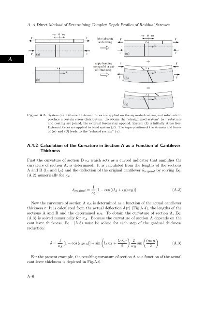
Figure A.5: System (a): Balanced external forces are applied on the separated coating and substrate to<br />
produce a certain stress distribution. To obtain the ”straightened system” (α), substrate<br />
and coating are joined, the external forces stay applied. System (b) is initially stress free.<br />
External forces are applied to bend system (β). The superposition of the stresses and forces<br />
of (α) and (β) leads to the ”relaxed system” (γ).<br />
A.4.2 Calculation of the Curvature in Section A as a Function of Cantilever<br />
Thickness<br />
First the curvature of section B κb which acts as a curved indicator that amplifies the<br />
curvature of section A, is determined. It is calculated from the lengths of the sections<br />
A and B (lA and lB) and the deflection of the original cantilever δoriginal by solving Eq.<br />
(A.2) numerically for κB:<br />
δoriginal = 1<br />
κb<br />
[1 − cos ((lA + lB) κB)] (A.2)<br />
Now the curvature of section A κA is determined as a function of the actual cantilever<br />
thickness t. It is calculated from the actual deflection δ (t) (Fig.A.4), the lengths of the<br />
sections A and B and the determined κB. To obtain the curvature of section A, Eq.<br />
(A.3) is solved numerically for κA. Because the curvature of section A depends on the<br />
cantilever thickness, Eq. (A.3) must be solved for each step of the gradual thickness<br />
reduction:<br />
δ = 1<br />
<br />
[1 − cos (lAκA)] + sin lAκA +<br />
κA<br />
lBκB<br />
<br />
2 lBκB<br />
sin<br />
2 κB 2<br />
(A.3)<br />
For the present example, the resulting curvature of section A as a function of the actual<br />
cantilever thickness is depicted in Fig.A.6.<br />
A–6